


- sales/support
Google Chat:---
- sales
+86-0755-88291180
- sales01
sales@spotpear.com
- sales02
dragon_manager@163.com
- support
tech-support@spotpear.com
- CEO-Complaints
zhoujie@spotpear.com
- Only Tech-Support
WhatsApp:13246739196
- Purchase/Shipping/Refund
WhatsApp:13424403025
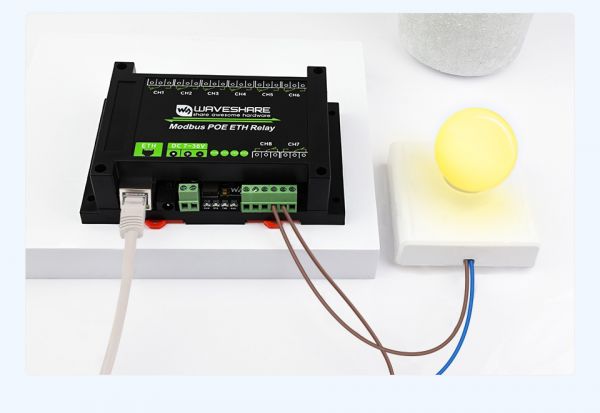
Modbus POE ETH Relay MQTT User Guide
Hardware Connection
- Connect the Modbus POE ETH Relay to the LAN via a network cable and power it through the power port or through POE.
Software Preparation
Get Started to Communicate
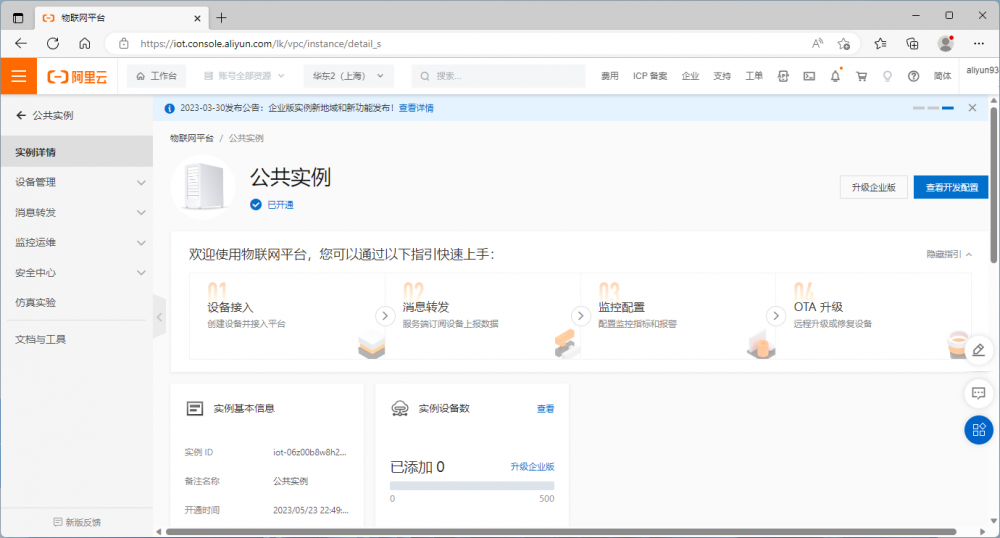
- Register an account to access the Alibaba Cloud IoT Platform and activate a public instance.
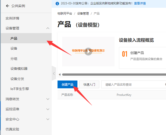
- Click Device Management -> Products -> Create a product, enter the product name, the example name is Waveshare, and choose a custom category to belong to. Other defaults are available.
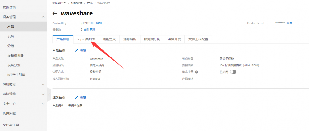
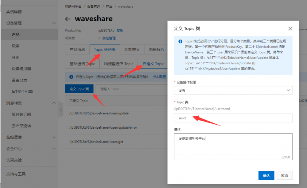
- After creating the product, click View Product Details below to enter the product page and select the Topic category list to go to the Topic page to add a custom topic.
- Select Topic class list -> Custom Topic -> Define Topic class, create a publish topic send to send data.
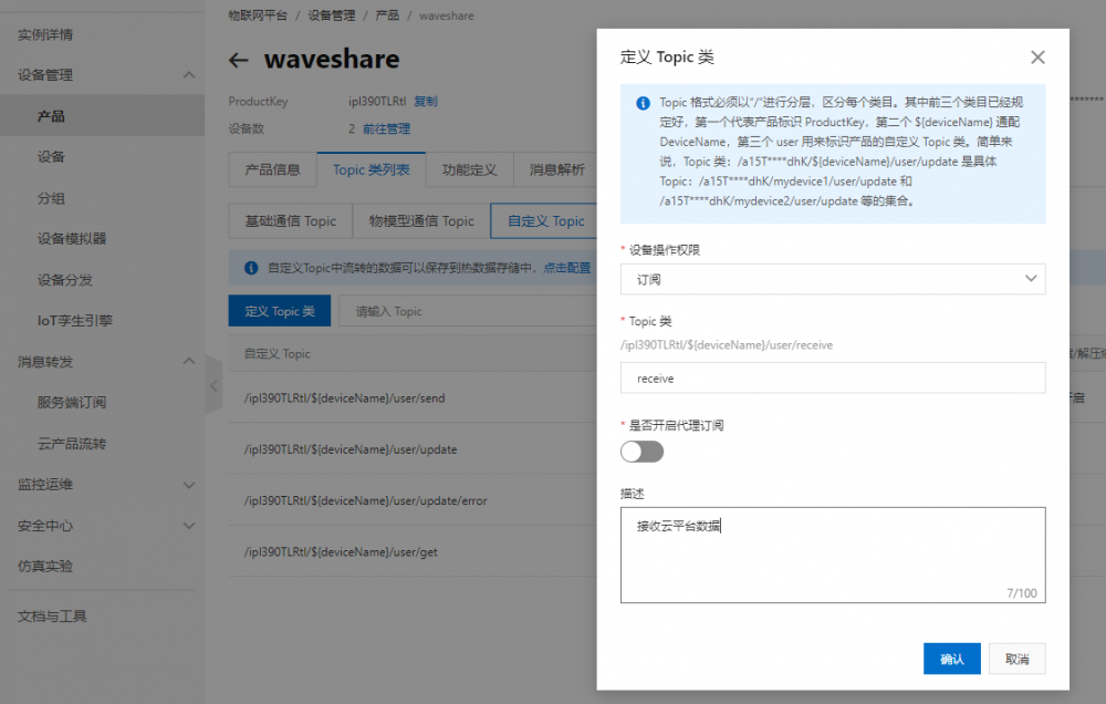
- To subscribe to a topic and receive data.
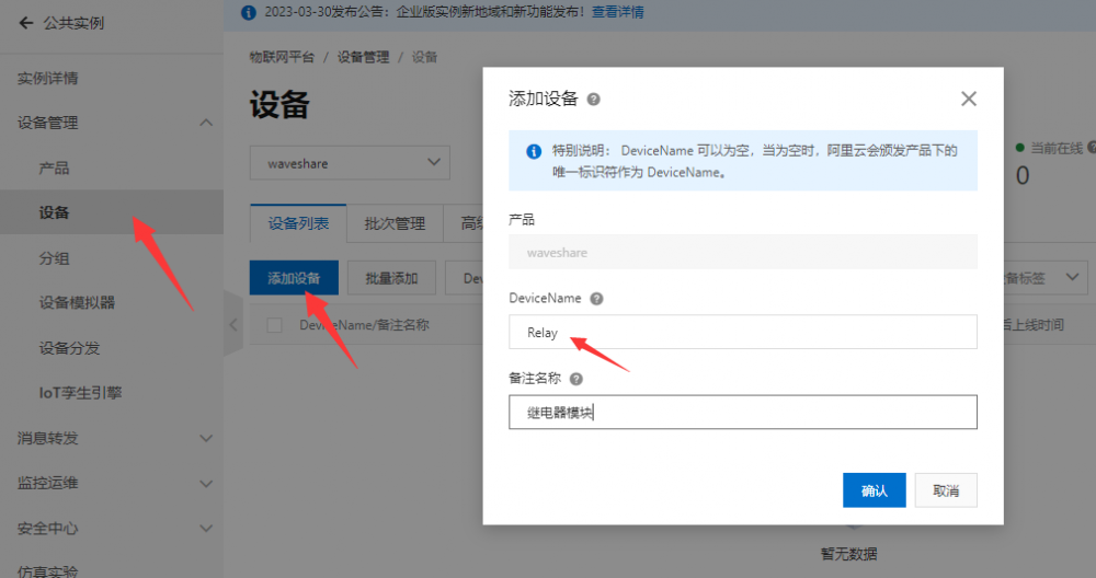
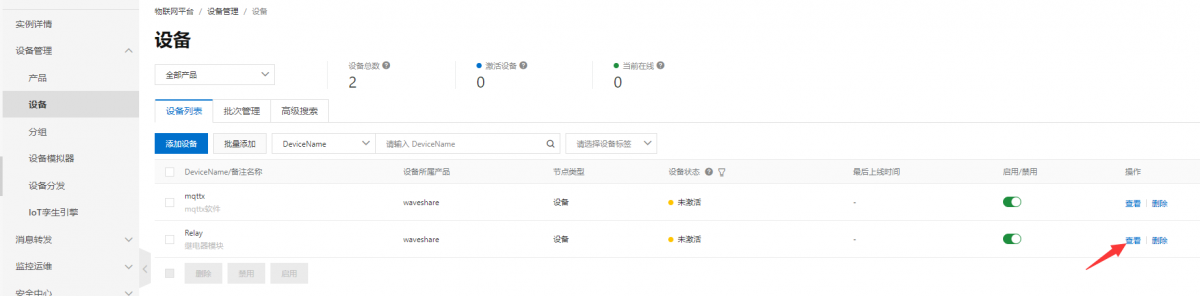
- Select Device Management -> Devices -> Add Device. Add a device named 'Relay', which is a relay module.
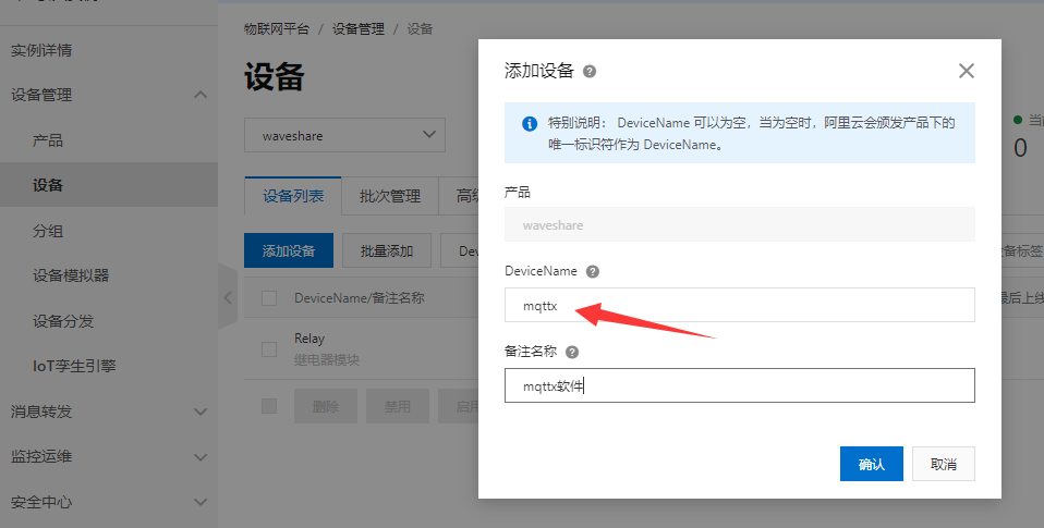
- For testing, you can add a device named mqttx device, the Ali cloud web page can only send text data and can not send binary data, so use mqttx software to facilitate debugging.
- After adding the devices, you can view two devices named "mqttx" and "relay" in the device list. Click on "View" to enter the page for the "Relay" device.
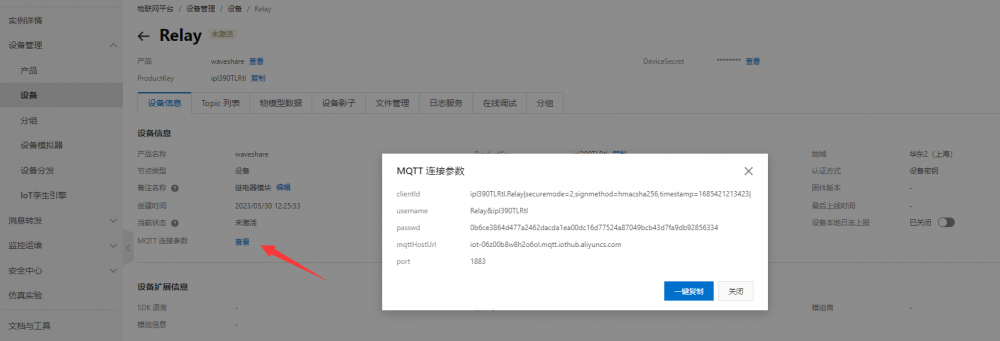
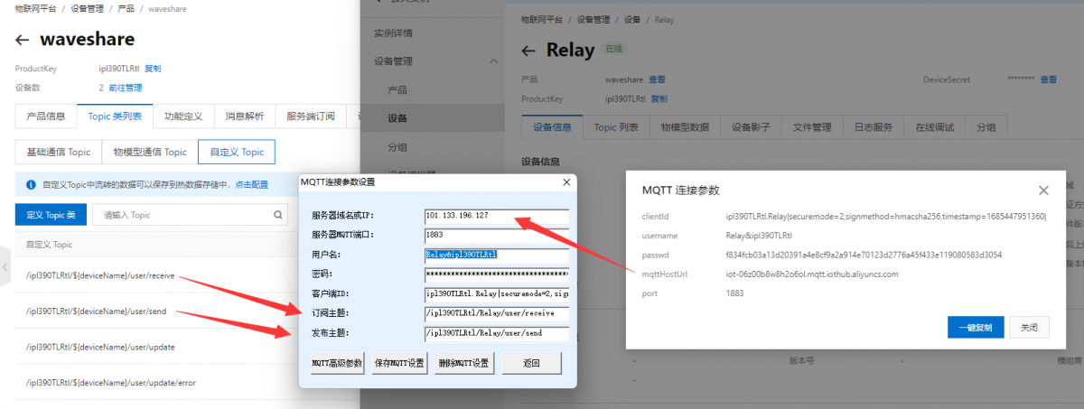
- Select "Device Information" -> "MQTT Connection Parameters" to view the MQTT connection parameters.
- Open Vircom -> Device Management -> left mouse click on the corresponding device -> Firmware and Configuration -> MQTT Configuration and enter the configuration page.
- Configure the connection parameters based on the Relay device MQTT connection information. When the configuration is complete, select Save MQTT Settings and click Download again.
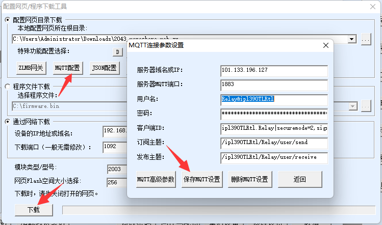
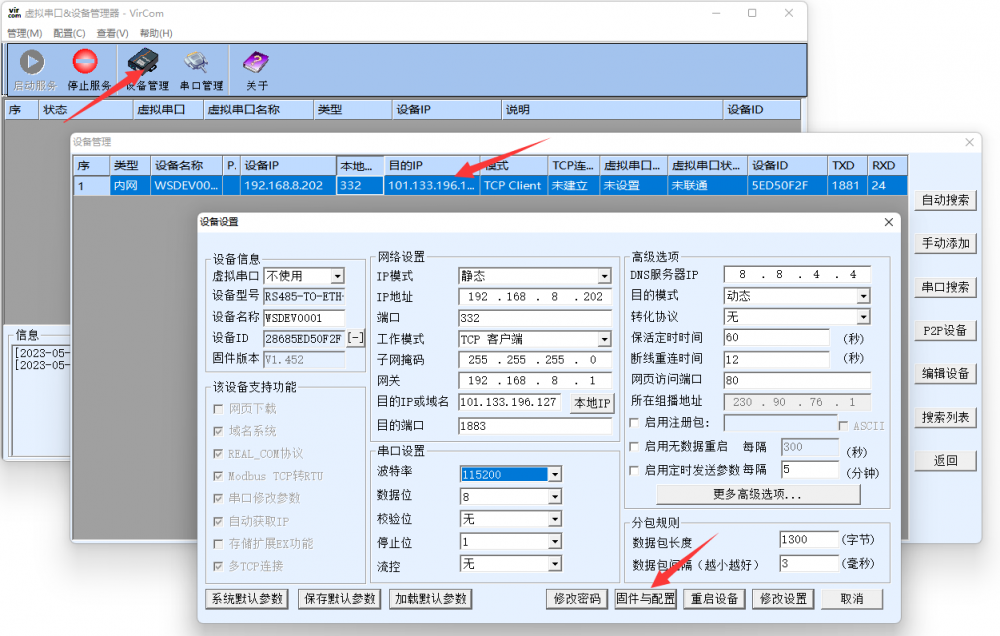
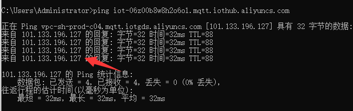
- Note: You can get the AliCloud IP address by pinging mqttHostUrl.
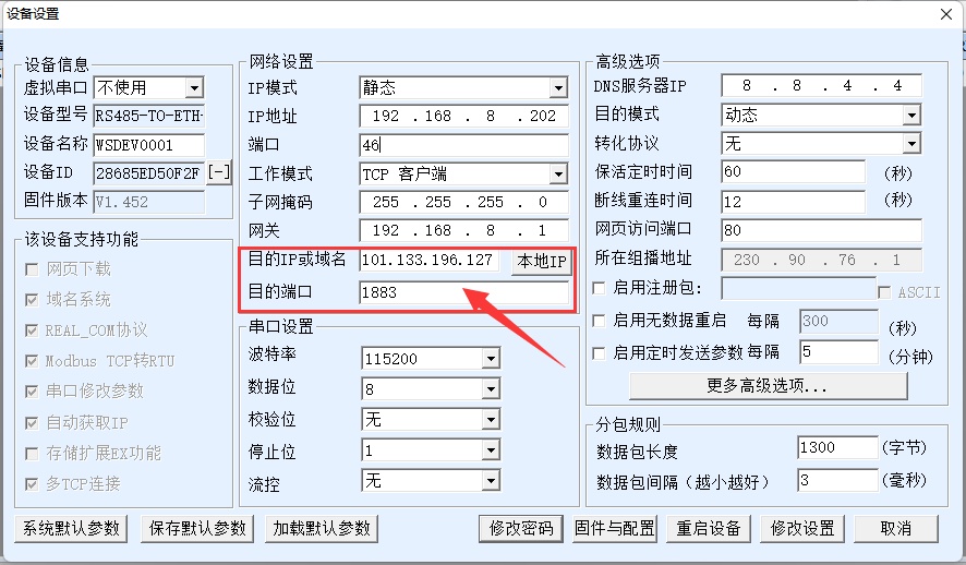
- Set the target IP and target port, and click Modify Settings to save. Note: If the local port is 0 then you need to modify a non-zero port, otherwise you cannot connect.
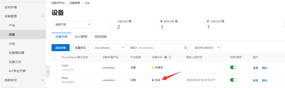
- After a successful connection, you can see that the Relay device has gone from inactive to online.
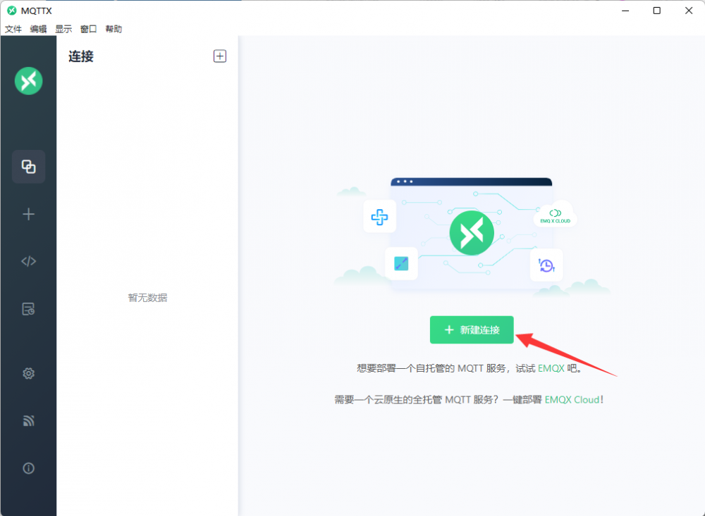
- Download the MQTTX software and install it, creat a new connection after successful installation.
- Create a new connection based on the mqttx device MQTT connection parameters.

- Add a subscription after a successful connection.
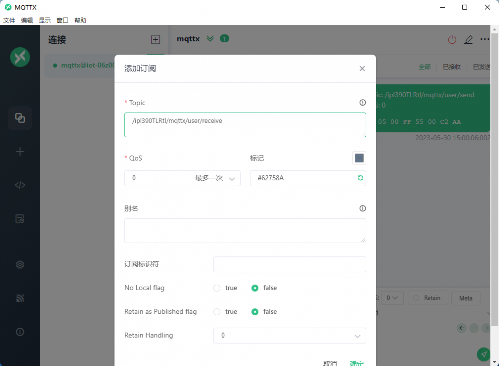
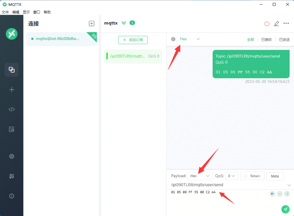
- Enter the sent topic, select hex to send and hex display, and send the data.
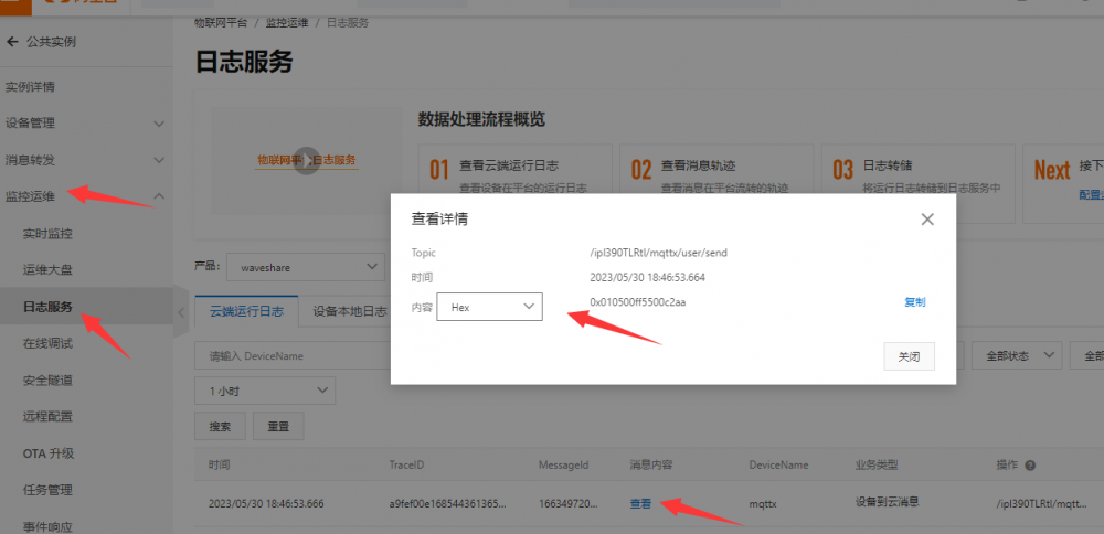
- Select Monitor Ops -> Log Services -> Cloud Operation Log to check the information received from the cloud and select hex to display.
- At this point, both the Relay device and the mqttx device have been connected to the cloud platform, but it is not yet possible to control the relays through the mqttx software, and finally, message forwarding needs to be added.
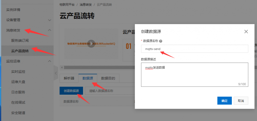
- Select Message Forwarding -> Cloud Product Flow -> Data Source -> Create Data Source, the data source name is mqttx-send.
- Go to edit page, add Topic, select custom, waveshare product, mqttx device, user/send topic.

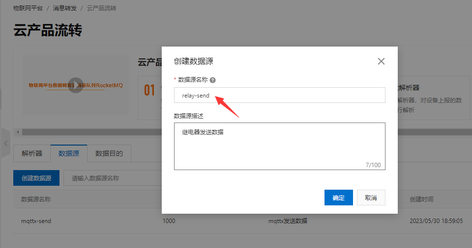
- Select Message Forwarding -> Cloud Product Flow -> Data Source -> Create Data Source and then add a data source with the name of relay-send.
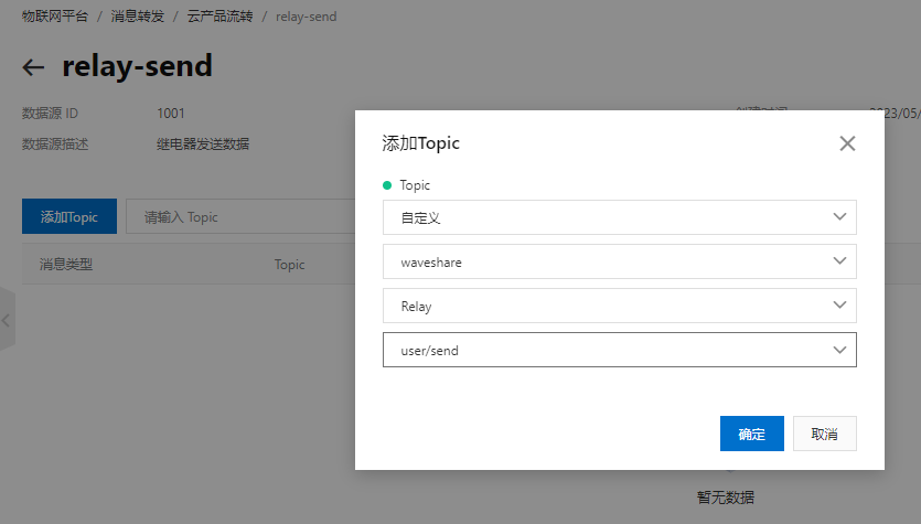
- Go to edit page, add Topic, select custom, waveshare product, relay device, user/send topic.
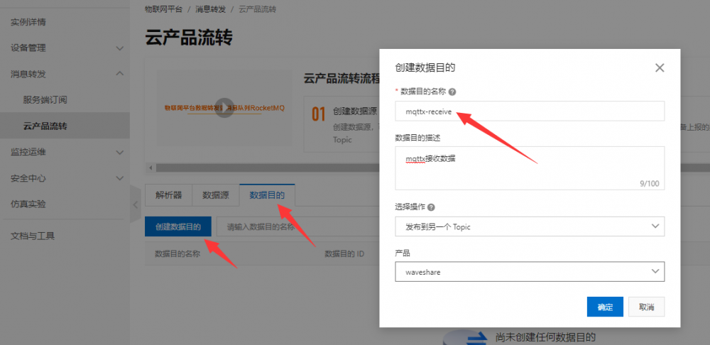
- Select Message Forwarding -> Cloud Product Flow -> Data Destination -> Create Data Destination, the data destination name is mqttx-receive.
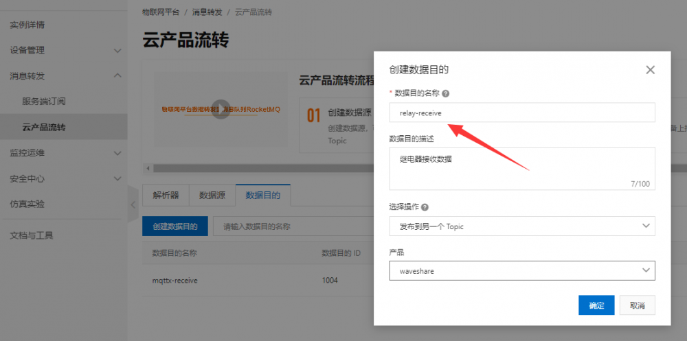
- Select Message Forwarding -> Cloud Product Flow -> Data Source -> Create a data source and then add a data destination with the name of relay-receive.
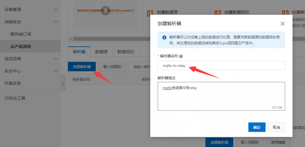
- Select Message Forwarding -> Cloud Product Flow -> Parser -> Create a parser with the name mqttx-to-relay.
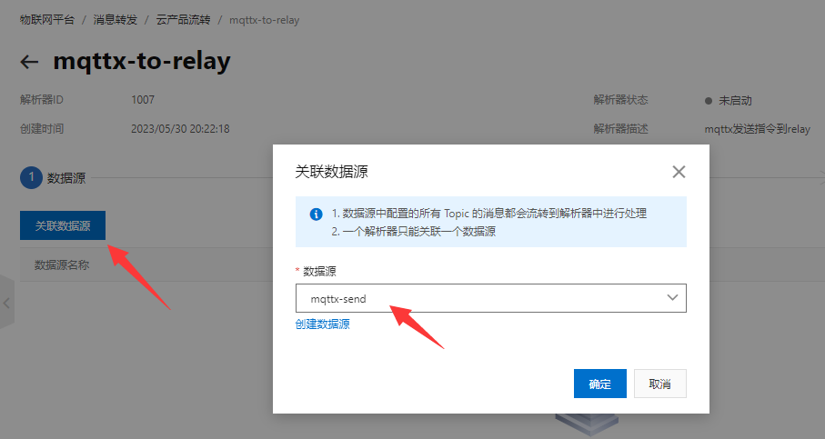
- Open mqttx-to-relay edit page -> Data Source -> Associated Data Source,Data Source select mqttx-send
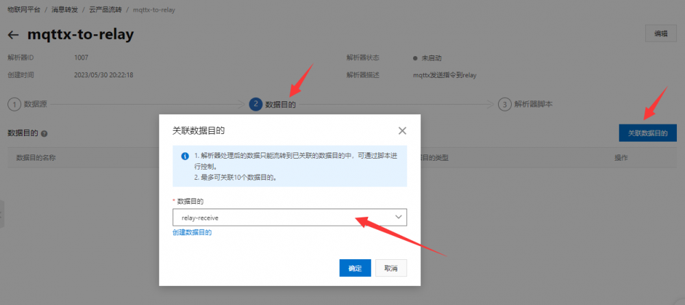
- Data destination -> associate data destination->data destination selection relay-receive
- Parser script, add the following code and publish, where 1005 is the relay-receive data destination ID, /ipl390TLRtl/Relay/user/receive is the relay receive topic, needs to be more practical to modify.
//Through the payload function, get the message content reported by the device and convert the payload data into binary variables for pass-through
var data = payload("binary");
//Forwarding data to relays
writeIotTopic(1005, "/ipl390TLRtl/Relay/user/receive", data);
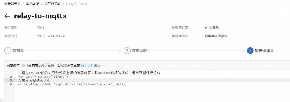
- Select Message Forwarding -> Cloud Product Flow -> Parser -> Create Parser then create a parser with the name relay-to-mqttx.

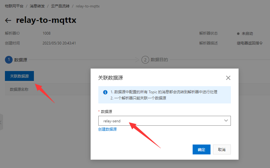
- Open mqttx-to-relay edit page -> data source -> associate data source, data source select relay-send.
- Data Destination -> Associate Data Destination -> Data Destination Select mqttx-receive.
- Parser script, add the following code and publish, where 1004 is the mqttx-receive data destination ID, /ipl390TLRtl/mqttx/user/receive is the mqttx receive topic, need to be more practical to modify.
//Through the payload function, get the message content reported by the device and convert the payload data into binary variables for pass-through
var data = payload("binary");
//Forwarding data to relays
writeIotTopic(1004, "/ipl390TLRtl/mqttx/user/receive", data);
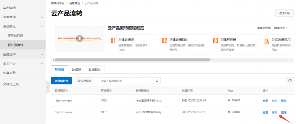
- Finally, select Start Parser to implement data forwarding. Message forwarding is configured and enabled.
- At this point, you can send commands to control the relays via MQTTX. Send the relay flip command as shown below. Under normal circumstances, the relay will be flipped and the command data will be returned.
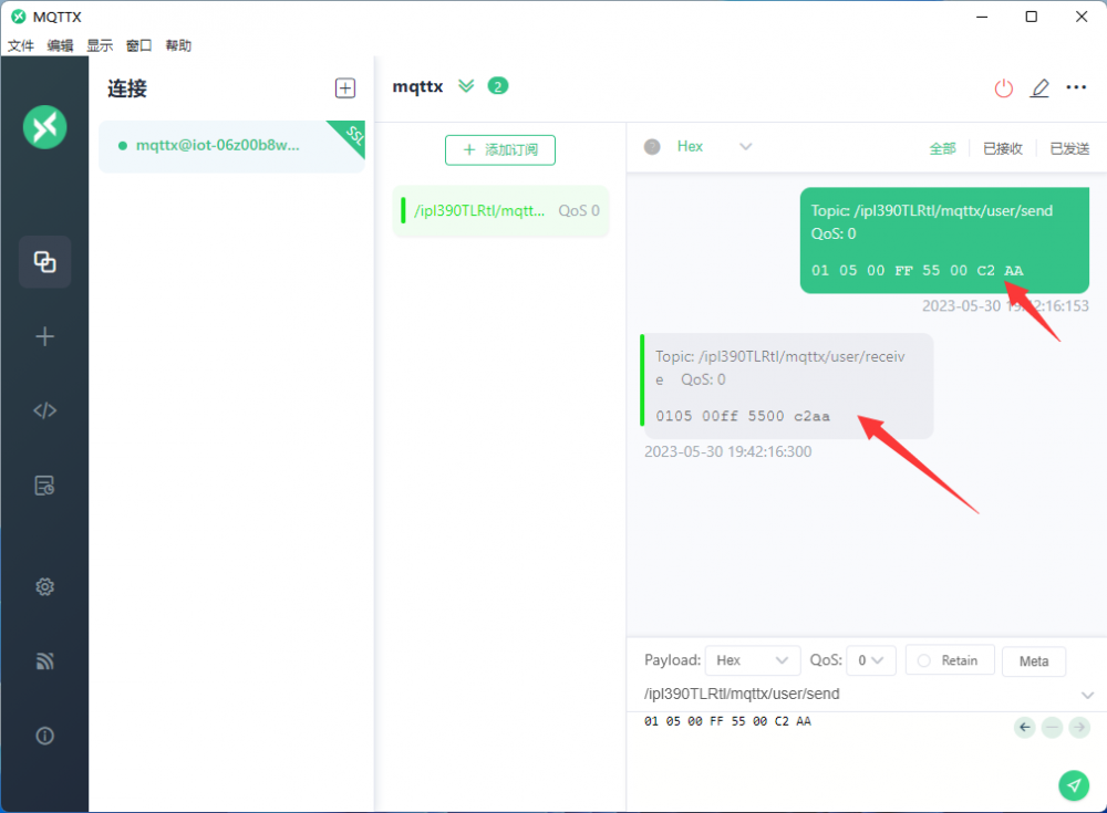
- The operation is now complete. You can try to send more Modbus commands to test. The data flow is shown below.
- MQTTX sends the command -> AliCloud receives the data and forwards it to relay -> relay receives the data to execute the action and return the data to AliCloud -> Ali cloud receives data and forwards to mqttx -> MQTTX receives the return data.
TAG:
Raspberry Pi 13.3 inch DSI MIPI Display 13.3inch LCD Capacitive TouchScreen 1920x1080
Raspberry Pi 4 Sound Card
ESP32 ST7789 tutorial
RS485 Bus
RP204 0.85inch LCD
Raspberry Pi CM5 Mini Base IO Board NANO A Development For Compute Module 5
Raspberry Pi 5 8mp Camera
ESP32-S3 AI Electronic Eye Development Doard DualEye TouchEye 1.28 inch TouchScreen LCD Round Display N16R8 Toy Doll Robot
D-Robotics RDK X3 Module Core MD Module Horizon Sunrise Pi ARM Cortex-A53 5Tops Size Compatible With Raspberry Pi CM4 Size
LuckFox
Code
ESP32-C5 WIFI6 Development Board ESP32-C5-WROOM-1 N16R4/N16R8
XIAO RA4M1 Tiny SuperMini Board For Arduino Uno IDE For SeeedStudio R7FA4M1
RP2040 Camera
Raspberry Pi 5 PCIe to M.2 NVMe SSD Adapter Board HAT
ESP32 ST7789
ESP32 S3 Development Board 1.85 inch Round LCD Display 360×360 QMI8658 Sensor / MIC / SD /MP3 Audio /Battery Port LVGL/HMI For Arduino
Jetson Nano Expansion Board
Raspberry Pi Pico 2 RP2350B Industrial 8-Channel Relay IOT LAN Digital Input DIO /RS485 /RJ45 Ethernet /POE
4.26inch-e-Paper
TAG:
XIAO ESP32 C6 MR60BHA2 60GHz mmWave Breathing and Heartbeat Detection Sensor ESPhome
Raspberry Pi RP2040 Keyboard
Changeable Photo Frames
ESP32-S3
Industrial RJ45 Ethernet To 16-ch Relay Module Modbus RTU TCP With Protection and guide rails
Pi5 Heatsink
Jetson 1.5inch LCD
ADXL355BEZ
IR Thermal Imaging Camera
ESP32-S3 1.28inch Round LCD Display TouchScreen Accelerometer Gyroscope Sensor Case
Microchip Official PICkit 5 Debugger Programmer Android MPLAB
D-Robotics RDK S100 Robot Development Kit Horizon Sunrise 80TOPS BPU 4 × USB3.0 Type-A
ESP32 RJ45
USB Type-C
Raspberry Pi PiKVM Type-C Power Signal Splitter With reverse power supply protection
ESP32-H2-MINI-1-N4 Module
Raspberry Pi 7.9 inch DSI LCD Display MIPI 400x1280 Capacitive TouchScreen
Camera
SIM8260G M2 3G/4G/5G/GNSS/GPS Sub-6G PCIe M.2 Moudle For LTE-A/NSA/SA For DFOTA /VoLTE For SIMCOM
Luckfox Lume Allwinner T153 Linux Development Board 128MB DDR3 Dual Gigabit Ethernet Ports