- sales/support
Google Chat:---
- sales
+86-0755-88291180
- sales01
sales@spotpear.com
- sales02
dragon_manager@163.com
- support
tech-support@spotpear.com
- CEO-Complaints
zhoujie@spotpear.com
- Only Tech-Support
WhatsApp:13246739196
- Purchase/Shipping/Refund
WhatsApp:13424403025
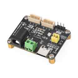
Bus Servo Adapter (A) User Guide
Serial Bus Servo Driver Circuit
Demo
- ST serial bus servo control library (Python)
- ST/SC serial bus servo control library (Arduino IDE)
- ST/SC serial bus servo control library (Linux)
- ST series STM32F103 SDK
- SC series servo sample demo
- ST series servo sample demo
Introduction
This is a serial bus servo adapter board integrating the servo power supply and servo control circuit. The demo with a different language for controlling the serial bus servo is provided and supports changing the servo ID and operation mode (Servo mode/Motor mode) through the demo. Theoretically, up to 253 serial bus servos can be controlled and each servo can read the information such as the current angle, load, voltage, mode, etc. Also, we can control the rotation of the serial bus servo by connecting the UART port to the host, which is applicable for robotic arms, hexapod robots, humanoid robots, wheeled robots, and other robotic projects that require feedback on servo angle and load.
Specification
- Input voltage: 9~12.6V (should match servo voltage)
- Communication interface: UART
- Power supply interface: 5.5*2.1mm DC
- Dimensions: 42mm x 33mm
- Mounting hole diameter: 2.5mm
Specification
- Support connecting to a host computer or MCU to control the serial bus servos.
- Simultaneous control of up to 253 ST/SC series serial bus servos (require sufficient power).
- 9~12.6V voltage input (input voltage must match servo voltage).
- Integrated stable control circuit to ensure stable operation of serial bus servos.
- Provide a convenient solution for serial bus servo control.
- Mini and space-saving, suitable for embedding into various projects with high space requirements.
Open-source Project
You can download the relevant open-source robot models in the product literature for building your own projects.
How to Use
UART Control
For hardware devices without USB connectors, such as Raspberry Pi Zero, ESP32, Arduino, and STM32 development board, you can realize serial bus servo control and data feedback via the UART port with the hardware device, and the connection must be RX-RX, TX-TX. Note that the jumper cap of the bus servo adapter must be on the A as shown below.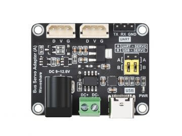
Take Raspberry Pi Zero as an example, we describe how to connect the serial bus servo to with UART port. Connect the serial bus servo to the servo interface of the driver board, and connect the UART serial port with the Raspberry Pi Zero with wires. Please notice that the jumper cap of the serial bus servo driver board should be in the A position. The power supply of the Raspberry Pi Zero is 5V, and you can input it with Micro USB and GPIO pins. The input voltage of the serial bus servo driver board should match the power supply of the connected serial bus servos, and you can input it via the DC5521 power header and green power screw terminal.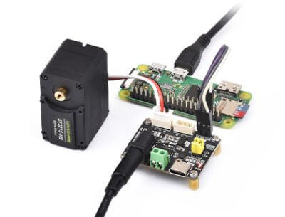
Note: If you use an SC series servo, you need the power supply to match the SC series servos. The voltage marking on the power supply interface of the driver board is specified for the power voltage of the ST series servos, but in reality, it can also accept the power voltage for the SC series servos.
Python Example
Python Environment Setup On Windows
First, download the latest installation package from the Python website. Please download it according to your OS. Here the package I downloaded is Python 3.11.5 for Windows.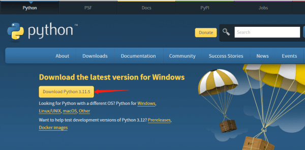
After downloading, double-click python-3.11.5-amd64 to install, and click "Customize installation" to enter "Optional Features". Keep clicking on "Next" to enter the "Advanced Options" interface. Be sure to keep "Add Python to environment variables" checked, and click "Browse" to modify the installation address. Here is the default installation address. Click "Install" after setting, and then just wait for the installation.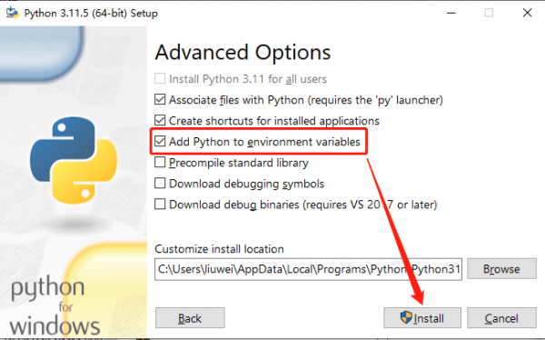
Once installed, let's move on to the Python project compilation example.
ST Series Servo Python Example
Download [] demo, unzip, and then input "cmd" in the start menu bar to open the Windows command prompt interface, type "cd folder path" to enter the STServo_Python project folder, where the virtual environment has been created, the name is stservo-env, and then enter:
stservo-env\Scripts\activate.bat
This command is to activate the virtual environment.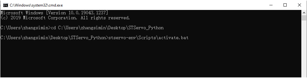
In the STServo_Python project, you can see the "requirements.txt" file, which is for storing the installation package list used in this project. After entering the virtual environment, input:
python -m pip install -r requirements.txt
This command can be used to install the package in this project, and you can see the package to be used only is "pyserial" and has been installed.
To connect the ST series servos to the serial bus servo interface on the driver board and provide power with a voltage range of 9 to 12.6V, you can search for 'Device Manager' in the Start menu to view the newly connected port number.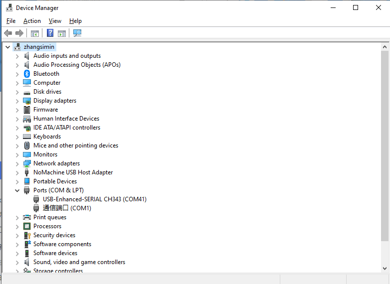
Next, change the name of the device in the demo you want to run to the access port number, in my case COM41 (different computers have different access port numbers).
Once modified you can run it, here is an example of the ping.py file, enter:
python ping.py
You can see it runs successfully and the servo with ID 1 is connected successfully.
These are simple tutorials for Python examples, and SDKs for different hardware devices and demos for different languages are provided in the documentation.