


- sales/support
Google Chat:---
- sales
+86-0755-88291180
- sales01
sales@spotpear.com
- sales02
dragon_manager@163.com
- support
tech-support@spotpear.com
- CEO-Complaints
zhoujie@spotpear.com
- Only Tech-Support
WhatsApp:13246739196
- Purchase/Shipping/Refund
WhatsApp:13424403025
- HOME
- >
- ARTICLES
- >
- Common Moudle
- >
- ESP
ESP32-S3-Touch-LCD-3.5B User Guide
Overview
Introduction
This product is a high-performance, highly integrated microcontroller development board designed by Waveshare. It is equipped with a 3.5inch capacitive high-definition IPS screen, a highly integrated power management chip, a 6-axis sensor (3-axis accelerometer and 3-axis gyroscope), RTC, low-power audio codec chip and other peripherals, which are convenient for development and embedding into the product. No assembly or wiring is required, so it's easy to play with Xiaozhi AI.
Features
- Equipped with ESP32-S3R8 high-performance Xtensa 32-bit LX7 dual-core processor, up to 240MHz main frequency
- Supports 2.4GHz Wi-Fi (802.11 b/g/n) and Bluetooth 5 (BLE), with onboard antenna
- Built in 512KB SRAM and 384 KB ROM, with onboard 8MB PSRAM and an external 16MB Flash
- Adopts Type-C interface to improve user convenience and device compatibility
- Built-in 3.5inch capacitive touch high-definition IPS display with a resolution of 320×480, 262K colors for clear color pictures
- Embedded AXS15231B display driver integrated circuit (DDIC), SPI/I2C communication
- Onboard QMI8658 6-axis IMU (3-axis accelerometer and 3-axis gyroscope) for detecting device deflection status, step counting, etc.
- Onboard PCF85063 RTC chip connected to the battery via the AXP2101 for uninterrupted power supply, and a backup battery pad is reserved to ensure that the RTC function continues to work during main battery replacement
- Onboard PWR and BOOT two side buttons with customizable functions, allowing for custom function development
- Onboard 3.7V MX1.25 lithium battery recharge/discharge header
- Lead out I2C, UART, USB and multiple GPIOs, which can be used for external devices and debugging, and flexibly configure peripheral functions
- Onboard TF card slot for extended storage and fast data transfer, flexible for data recording and media playback, simplifying circuit design
- Onboard camera interface, support mainstream cameras such as OV5640 and OV2640
- The benefits of using AXP2101 include efficient power management, support for multiple output voltages, charging and battery management functions, and optimization for battery life
Hardware Description
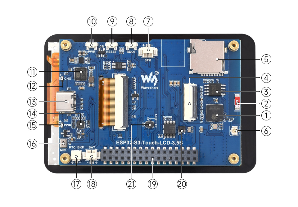
1. ESP32-S3R8 2. Onboard SMD antenna 3. W25Q128JVSIQ 4. Camera interface 5. TF card slot 6. IPEX Gen 1 connector 7. MX1.25 Speaker interface 8. BOOT button 9. RESET button 10. PWR button 11. AXP2101 | 12. Charge indicator 13. Type-C interface 14. ES8311 15. Power indicator 16. Microphone 17. SH1.0 RTC battery interface 18. MX1.25 Lithium battery interface 19. 2.54mm socket interface 20. PCF85063 21. QMI8658 |
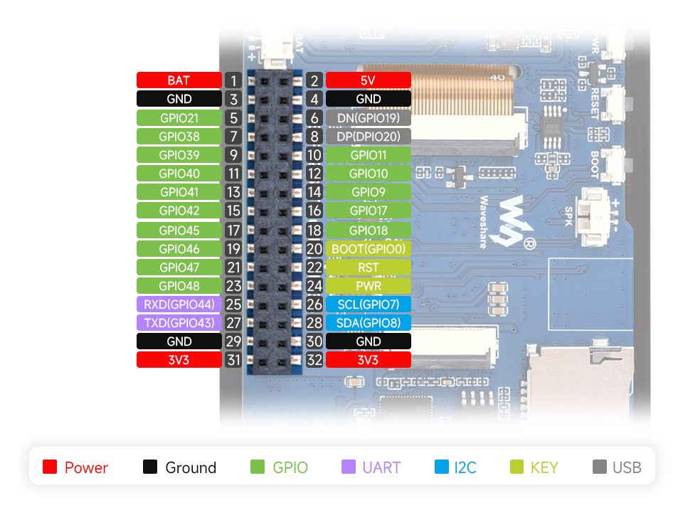
Pinout Definition
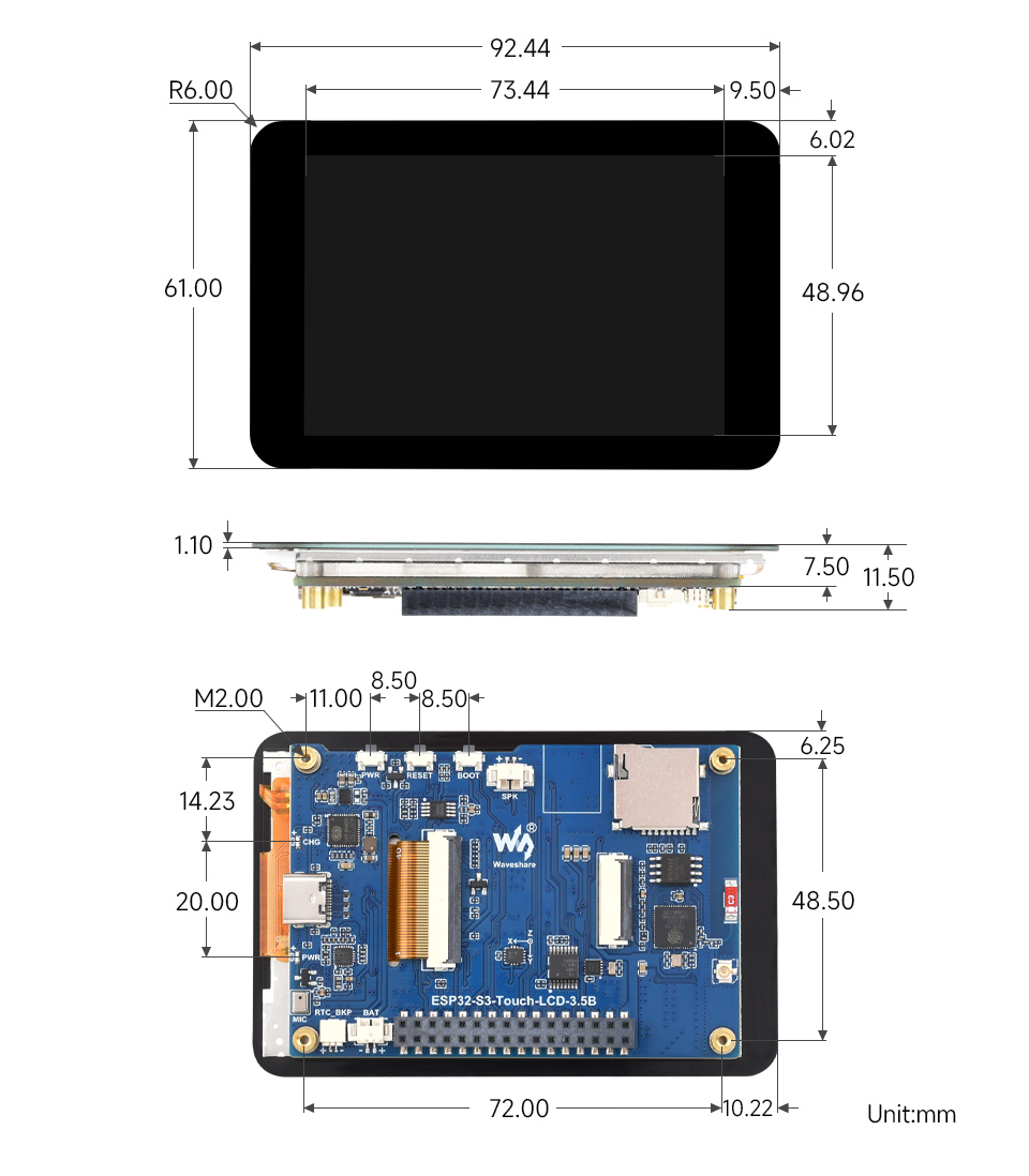
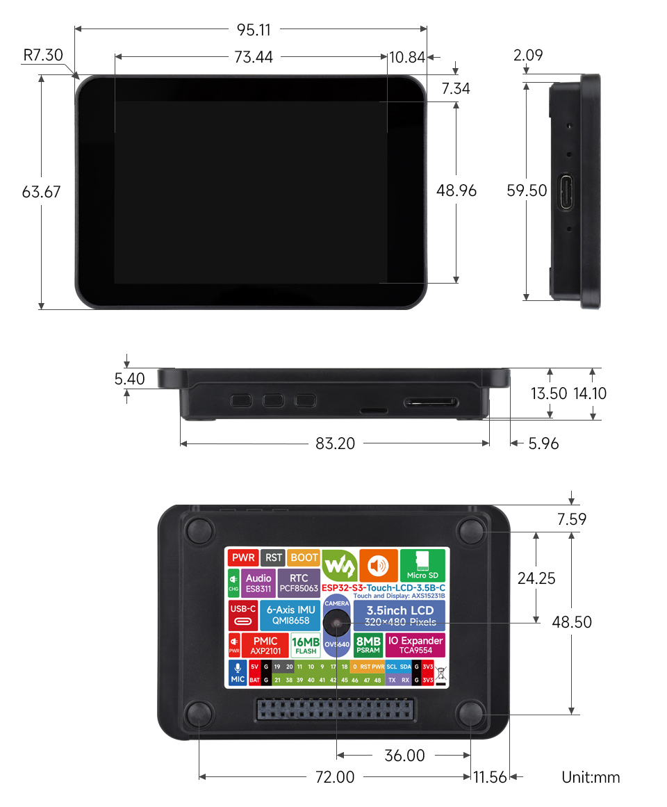
Dimensions
Usage Instructions
ESP32-S3-Touch-LCD-3.5B currently provides two development tools and frameworks, Arduino IDE and ESP-IDF, providing flexible development options, you can choose the right development tool according to your project needs and personal habits.
Development Tool
| Arduino IDEArduino IDE is an open source electronic prototyping platform, convenient and flexible, easy to get started. After a simple learning, you can start to develop quickly. At the same time, Arduino has a large global user community, providing an abundance of open source code, project examples and tutorials, as well as rich library resources, encapsulating complex functions, allowing developers to quickly implement various functions. |
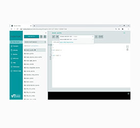
| ESP-IDFESP-IDF, or full name Espressif IDE, is a professional development framework introduced by Espressif Technology for the ESP series chips. It is developed using the C language, including a compiler, debugger, and flashing tool, etc., and can be developed via the command lines or through an integrated development environment (such as Visual Studio Code with the Espressif IDF plugin). The plugin offers features such as code navigation, project management, and debugging, etc. |
Each of these two development approaches has its own advantages, and developers can choose according to their needs and skill levels. Arduino are suitable for beginners and non-professionals because they are easy to learn and quick to get started. ESP-IDF is a better choice for developers with a professional background or high performance requirements, as it provides more advanced development tools and greater control capabilities for the development of complex projects.
Components Preparation
- ESP32-S3-Touch-LCD-3.5B x1
- TF card x 1
- OV5460 x1
- USB cable (Type-A male to Type-C male) x1
Working with Arduino
This chapter introduces setting up the Arduino environment, including the Arduino IDE, management of ESP32 boards, installation of related libraries, program compilation and downloading, as well as testing demos. It aims to help users master the development board and facilitate secondary development. 
Environment Setup
Download and Install Arduino IDE
- Click to visit the Arduino official website, select the corresponding system and system bit to download
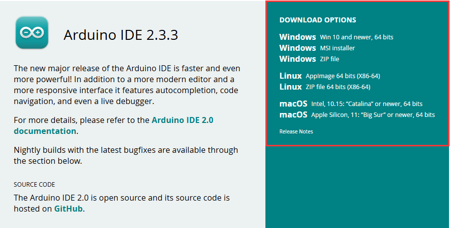
- Run the installer and install all by default
Install ESP32 Development Board
- Before using ESP32-related motherboards with the Arduino IDE, you must first install the software package for the esp32 by Espressif Systems development board
- According to board installation requirement, it is generally recommended to use Install Online. If online installation fails, use Install Offline.
- For the installation tutorial, please refer to Arduino board manager tutorial
| Board name | Board installation requirement | Version number requirement |
|---|---|---|
| esp32 by Espressif Systems | "Install Offline" / "Install Online" | ≥3.2.0 |
Install Library
- When installing Arduino libraries, there are usually two ways to choose from: Install online and Install offline. If the library installation requires offline installation, you must use the provided library file
For most libraries, users can easily search and install them through the online library manager of the Arduino software. However, some open-source libraries or custom libraries are not synchronized to the Arduino Library Manager, so they cannot be acquired through online searches. In this case, users can onlymanually install these libraries offline. - ESP32-S3-Touch-LCD-3.5B library file is stored in the demo, click here to jump:ESP32-S3-Touch-LCD-3.5B Demo
- For library installation tutorial, please refer to Arduino library manager tutorial
| Library Name | Description | Version | Library Installation Requirement |
|---|---|---|---|
| lvgl | LVGL graphical library | v8.4.0 or v9.2.2 | "Install Online" |
| GFX_Library_for_Arduino | GFX graphics library | v1.6.0 | "Install Online" |
| XPowersLib | Power management library | v0.2.9 | "Install Online" |
| SensorLib | Sensor library | v0.3.1 | "Install Online" |
| ESP32-audioI2S-master | Audio processing library | v3.3.0 | "Install Online" |
| TCA9554 | Expand IO driver library | v0.1.2 | "Install Online" |
| OneButton | Button library | v2.6.1 | "Install Online" |
| esp_lcd_touch_axs15231b | Touch driver | --- | "Install Offline" |
| es8311 | es8311 driver library | --- | "Install Offline" |
Run the First Arduino Demo
New Project
- Run the Arduino IDE and select
File->New Sketch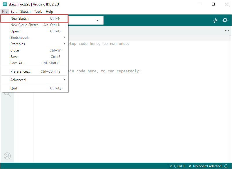
- Enter the code:
void setup() {
// put your setup code here, to run once:
Serial.begin(115200);
}
void loop() {
// put your main code here, to run repeatedly:
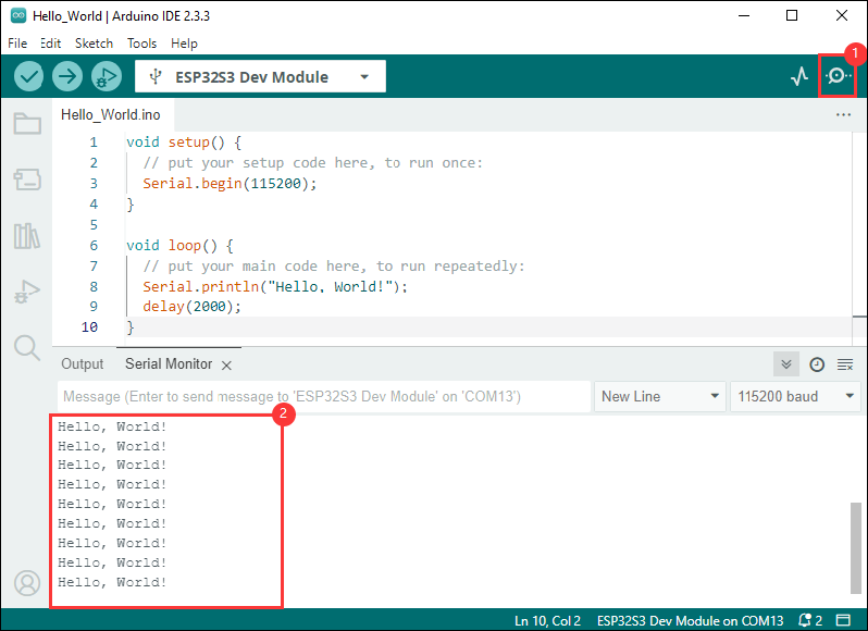
Serial.println("Hello, World!");
delay(2000);
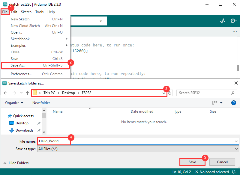
}- Save the project and select
File->Save As.... In the pop-up menu, select the path to save the project, and enter a project name, such as Hello_World, clickSave
Compile and Flash Demos
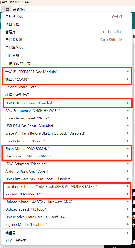
- Select the corresponding development board, take the ESP32S3 motherboard as an example:
①. Click to select the dropdown menu option Select Other Board and Port;
②. Search for the required development board model esp32s3 dev module and select;
③. Select COM Port;
④. Save the selection.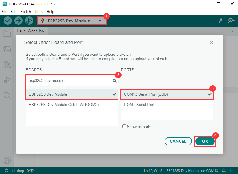
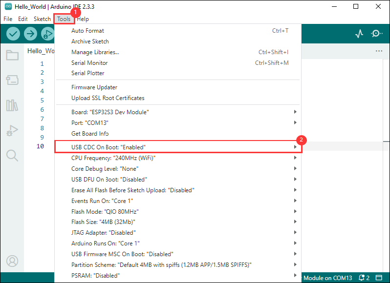
- If the ESP32S3 mainboard only has a USB port, you need to enable USB CDC, as shown in the following diagram:
- Compile and upload the program:
①. Compile the program; ②. Compile and download the program; ③. Download successful.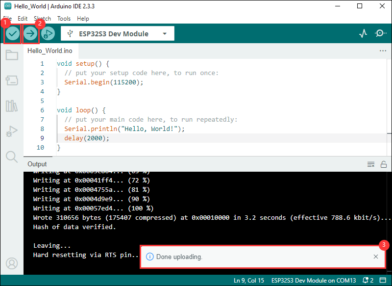
- Open the Serial Monitor window, and the demo will print "Hello World!" every 2 seconds, and the operation is as follows:
Demo

| Demo | Basic Description | Dependency Library |
|---|---|---|
| 01_audio_out | Read and play the audio file from the TF card | ESP32-audioI2S-master, es8311 |
| 02_axp2101_example | Print the data of the power management chip | XPowersLib |
| 03_button_example | BOOT button click, double click, long press, etc. | OneButton |
| 04_es8311_example | Record for a while and play | es8311 |
| 05_pcf85063_example | Print the data acquired by the RTC | SensorLib |
| 06_qmi8658_example | Print the IMU data | SensorLib |
| 07_sd_test | Test the read and write of the TF card | --- |
| 08_gfx_helloworld | HelloWorld displayed on the screen | GFX_Library_for_Arduino, TCA9554 |
| 09_lvgl_arduino_v8 | lvgl v8 demo | lvgl (v8.4.0), GFX_Library_for_Arduino, TCA9554, esp_lcd_touch_axs15231b |
| 10_lvgl_arduino_v9 | lvgl v9 demo | lvgl (v9.2.2), GFX_Library_for_Arduino, TCA9554, esp_lcd_touch_axs15231b |
| 11_camera_web_server | Display the camera images on the web page | XPowersLib |
- ESP32-S3-Touch-LCD-3.5B Arduino project parameter setting
01_audio_out
【Demo description】
This demo demonstrates how ESP32-S3-Touch-LCD-3.5B reads audio files from a TF card and plays them using a speaker, supporting formats such as MP3, AAC, WAV, etc.
【Preparation】
- Insert the TF card into the computer
- Create a folder named music in the root directory of the TF card
- Copy the 1.mp3 file from the data folder of this project to the music folder on the TF card
- Insert the TF card into ESP32-S3-Touch-LCD-3.5B
【Code analysis】
- Set the audio file to play
audio.connecttoFS(SD_MMC, "music/1.mp3");
【Result demonstration】
- Nothing will be shown on the screen if you play the audio file
02_axp2101_example
【Demo description】
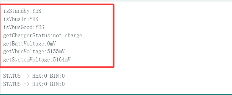
This demo demonstrates using XPowers to drive AXP2101 and print data via serial port.
【Code analysis】
- Initialize
  bool result = power.begin(Wire, AXP2101_SLAVE_ADDRESS, i2c_sda, i2c_scl);

  if (result == false) {
    Serial.println("power is not online...");
    while (1) delay(50);
  }
【Result demonstration】
- Nothing will be shown on the screen
- Open the serial port monitor
03_button_example
【Demo description】
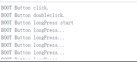
This example demonstrates how to use the OneButton library to drive the BOOT button and print click, double click, and long press events via the serial port.
【Code analysis】
- Bind callback functions
  button1.attachClick(click1);
  button1.attachDoubleClick(doubleclick1);
  button1.attachLongPressStart(longPressStart1);
  button1.attachLongPressStop(longPressStop1);
  button1.attachDuringLongPress(longPress1);
【Result demonstration】
- Nothing will be shown on the screen
- Open the serial port monitor
04_es8311_example
【Demo description】
This demo demonstrates using the ESP32-S3-Touch-LCD-3.5B to drive the ES8311 audio codec to achieve audio recording and playback functions.
【Code analysis】
- Initialize
  Wire.begin(I2C_SDA, I2C_SCL);
  es8311_codec_init();
  setupI2S();
- Record audio for 5s and play the recorded content
  wav_buffer = i2s.recordWAV(5, &wav_size);
  delay(1000);
  Serial.println("I2S playWAV");
  i2s.playWAV(wav_buffer, wav_size);
【Result demonstration】
- Nothing will be shown on the screen
- Press the RST button on the ESP32-S3-Touch-LCD-3.5B to enter audio recording mode, and 2 seconds later, it will play the recorded content.
05_pcf85063_example
【Demo description】
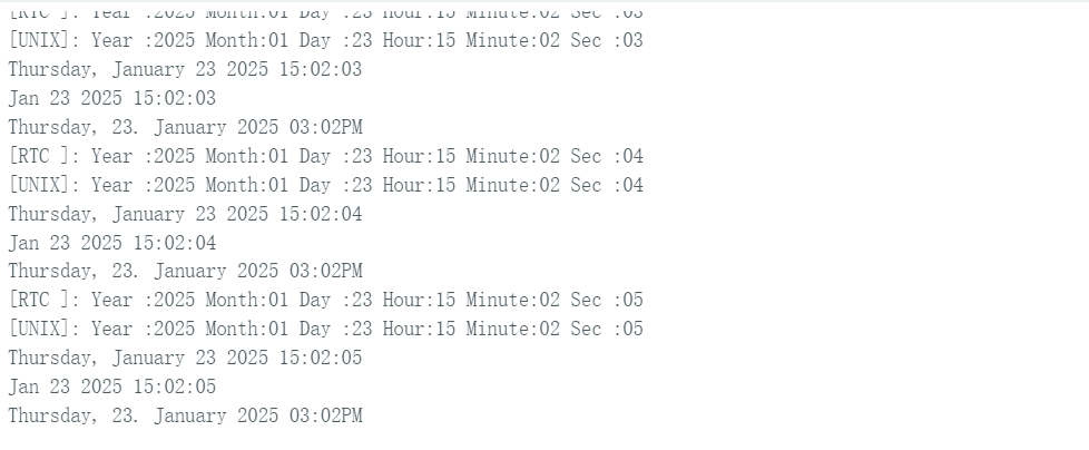
This demo demonstrates the ESP32-S3-Touch-LCD-3.5B driving the PCF85063 to set time, date, and retrieve time.
【Code analysis】
- Initialize
    if (!rtc.begin(Wire, PCF85063_SLAVE_ADDRESS, SENSOR_SDA, SENSOR_SCL)) {
        Serial.println("Failed to find PCF8563 - check your wiring!");
        while (1) {
            delay(1000);
        }
    }
- Set the time and date
rtc.setDateTime(year, month, day, hour, minute, second);
- Get the time and date
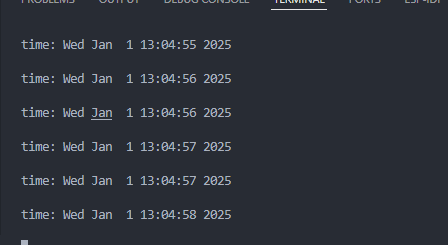
RTC_DateTime datetime = rtc.getDateTime();
【Result demonstration】
- Nothing will be shown on the screen
- Open the serial port monitor
06_qmi8658_example
【Demo description】
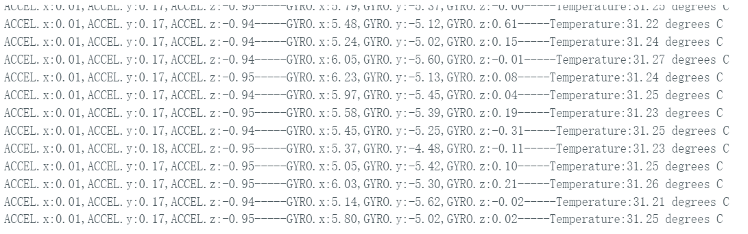
This demo demonstrates the ESP32-S3-Touch-LCD-3.5B driving QMI8658 to obtain and print the temperatures of Accel, Gyro, and IMU.
【Code analysis】
- Initialize
  if (!qmi.begin(Wire, QMI8658_L_SLAVE_ADDRESS, SENSOR_SDA, SENSOR_SCL)) {
    Serial.println("Failed to find QMI8658 - check your wiring!");
    while (1) {
      delay(1000);
    }
  }
- Get data
  if (qmi.getDataReady()) {
    if (qmi.getAccelerometer(acc.x, acc.y, acc.z)) {
    }
    if (qmi.getGyroscope(gyr.x, gyr.y, gyr.z)) {
    }
  }
【Result demonstration】
- Nothing will be shown on the screen
- Open the serial port monitor
07_sd_test
【Demo description】
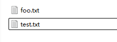
This demo demonstrates how to use ESP32-S3-Touch-LCD-3.5B to test the read and write functions of the TF card.
【Hardware connection】
- Connect the board to the computer
- Insert the TF card into the card slot (TF card needs to be formatted as FAT32)
【Code analysis】
- Initialize
  if(!SD_MMC.setPins(clk, cmd, d0)){
    Serial.println("Pin change failed!");
    return;
  }

  if (!SD_MMC.begin( "/sdcard", true)) {
    Serial.println("Card Mount Failed");
    return;
  }
【Result demonstration】
- Insert the TF card into the computer, and you can find two more files: test.txt and foo.test. The content of the foo.txt is Hello World!, and the content of the test.txt is empty
08_gfx_helloworld
【Demo description】
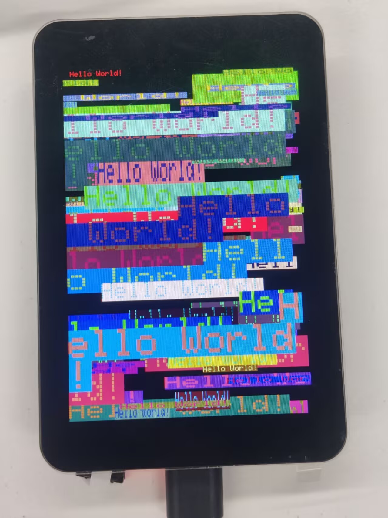
This demo demonstrates the ESP32-S3-Touch-LCD-3.5B using the GFX_Library_for_Arduino library to drive the screen and display HelloWorld on the screen.
【Code analysis】
- Configure the screen interface and screen resolution, etc.
Arduino_DataBus *bus = new Arduino_ESP32QSPI(LCD_QSPI_CS, LCD_QSPI_CLK, LCD_QSPI_D0, LCD_QSPI_D1, LCD_QSPI_D2, LCD_QSPI_D3);

Arduino_GFX *g = new Arduino_AXS15231B(bus, -1 /* RST */, 0 /* rotation */, false, 320, 480);

Arduino_Canvas *gfx = new Arduino_Canvas(320, 480, g, 0, 0, ROTATION);
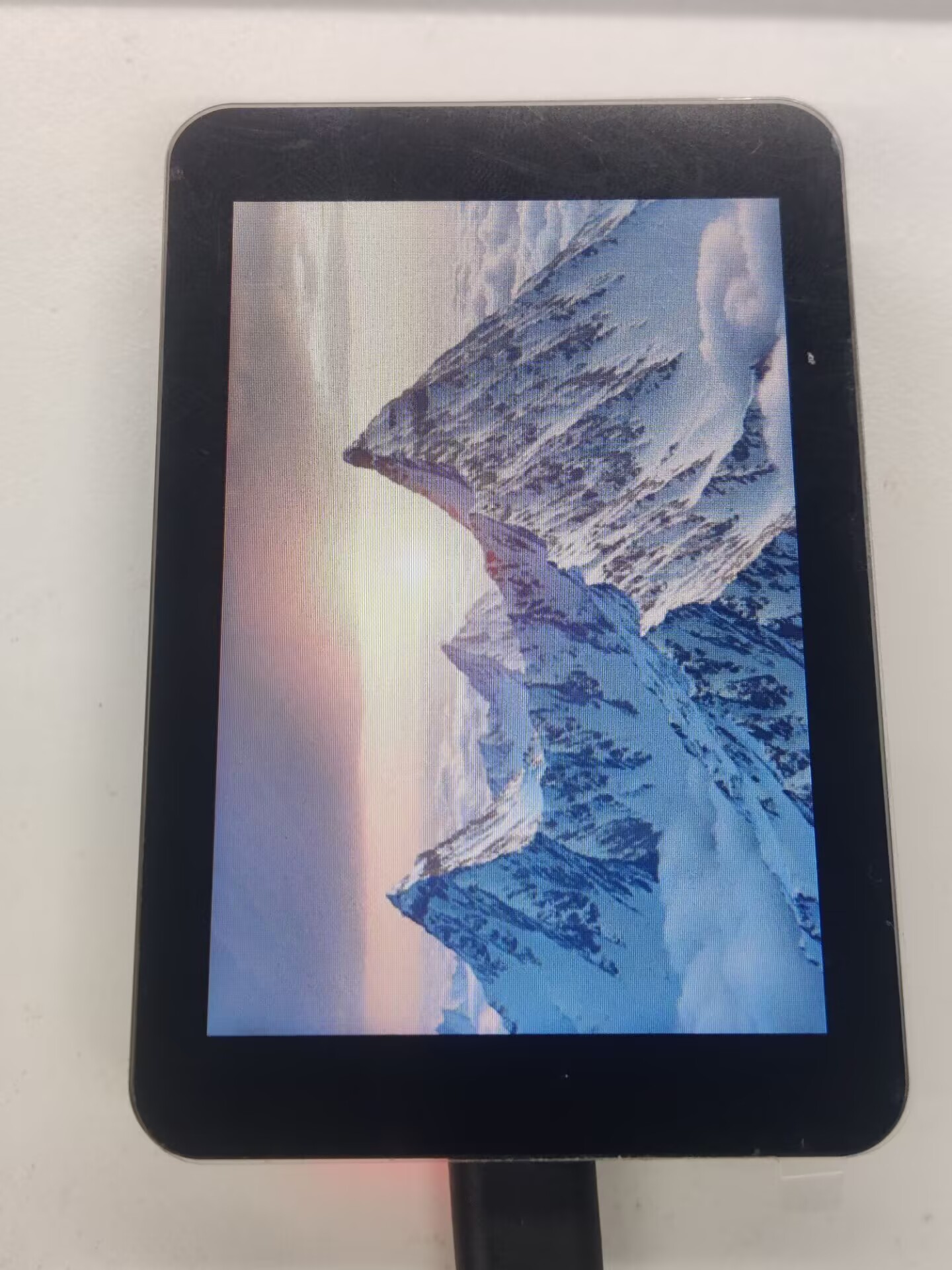
【Result demonstration】
09_lvgl_example_v8
【Demo description】
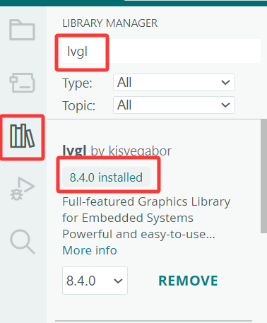
This demo demonstrates how to use ESP32-S3-Touch-LCD-3.5B to run the lvgl (v8.4.0) demos.
【Preparation】
- It is required to install lvgl v8.4.0 version. If you have installed other version, please reinstall.
【Code analysis】
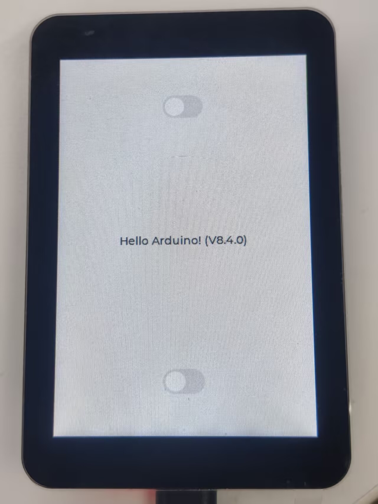
- UI initialization
    lv_obj_t *label = lv_label_create(lv_scr_act());
    lv_label_set_text(label, "Hello Arduino! (V" GFX_STR(LVGL_VERSION_MAJOR) "." GFX_STR(LVGL_VERSION_MINOR) "." GFX_STR(LVGL_VERSION_PATCH) ")");
    lv_obj_align(label, LV_ALIGN_CENTER, 0, 0);

    lv_obj_t *sw = lv_switch_create(lv_scr_act());
    lv_obj_align(sw, LV_ALIGN_TOP_MID, 0, 50);

    sw = lv_switch_create(lv_scr_act());
    lv_obj_align(sw, LV_ALIGN_BOTTOM_MID, 0, -50);
【Result demonstration】
- It can be operated by touch
10_lvgl_example_v9
【Demo description】
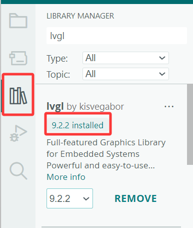
This demo demonstrates how to use ESP32-S3-Touch-LCD-3.5B to run the lvgl (v9.2.2) demos.
【Preparation】
- It is required to install lvgl v9.2.2 version. If you have installed other version, please reinstall.
【Code analysis】
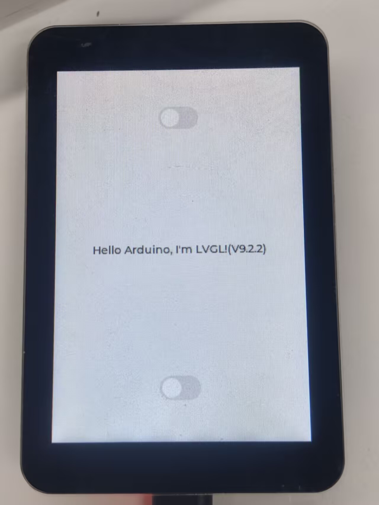
- UI initialization
    lv_obj_t *label = lv_label_create(lv_scr_act());
    lv_label_set_text(label, "Hello Arduino, I'm LVGL!(V" GFX_STR(LVGL_VERSION_MAJOR) "." GFX_STR(LVGL_VERSION_MINOR) "." GFX_STR(LVGL_VERSION_PATCH) ")");
    lv_obj_align(label, LV_ALIGN_CENTER, 0, 0);

    lv_obj_t *sw = lv_switch_create(lv_scr_act());
    lv_obj_align(sw, LV_ALIGN_TOP_MID, 0, 50);

    sw = lv_switch_create(lv_scr_act());
    lv_obj_align(sw, LV_ALIGN_BOTTOM_MID, 0, -50);
【Result demonstration】
- It can be operated by touch
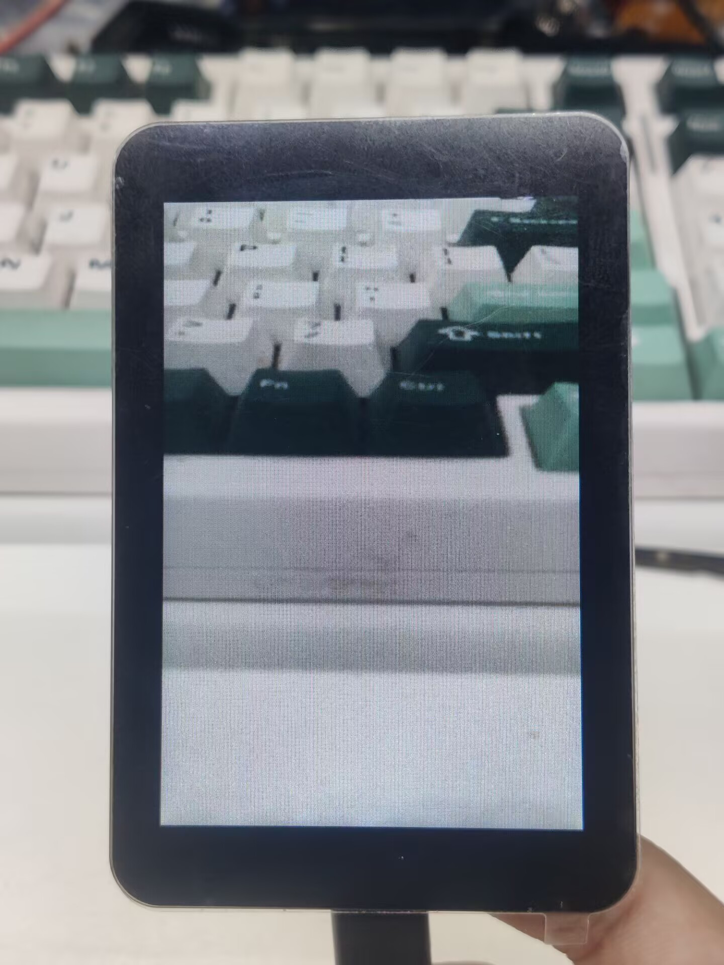
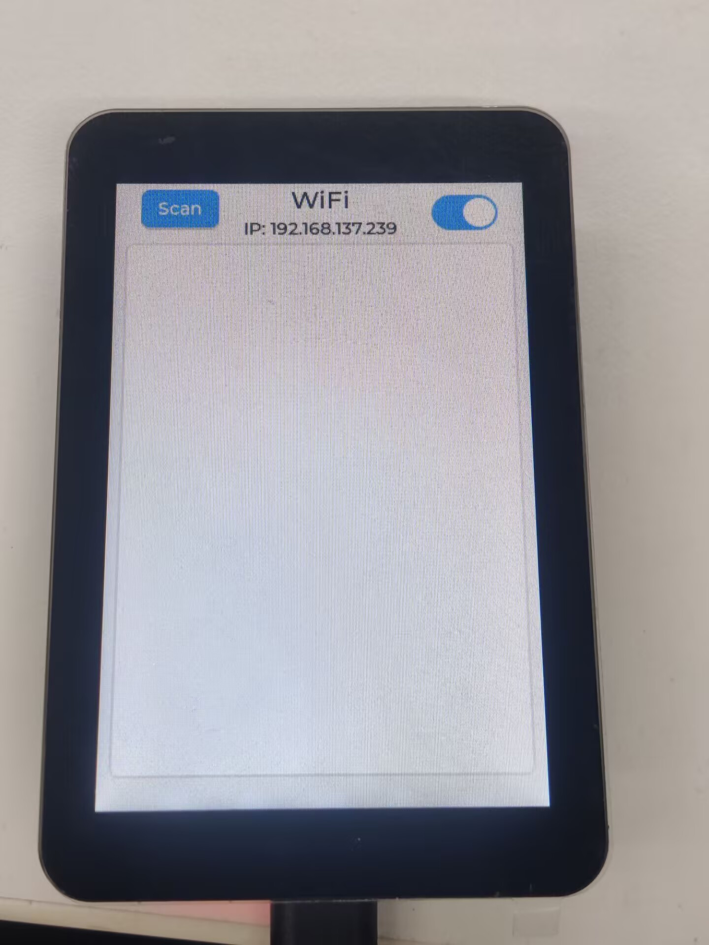
11_camera_web_server
【Demo description】
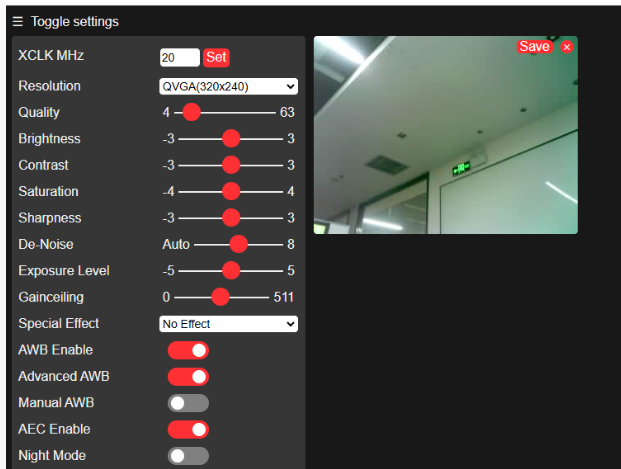
This demo demonstrates how to drive the camera. After connecting to WiFi, the program will create a web server, and users can access it by entering the device's IP address in the browser. Web pages can display images from cameras and support settings such as resolution and mirroring
【Preparation】
- Connect the board to the computer
- Plug the OV5640 camera into the 24Pin socket on the board (Version with casing does not require this operation)
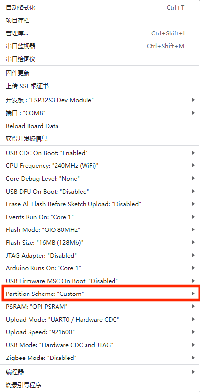
- Set Parttion to Custom
【Code analysis】
- Define the pins related to the camera
#define PWDN_GPIO_NUM -1
#define RESET_GPIO_NUM -1
#define XCLK_GPIO_NUM 38
#define SIOD_GPIO_NUM 8
#define SIOC_GPIO_NUM 7

#define Y9_GPIO_NUM 21
#define Y8_GPIO_NUM 39
#define Y7_GPIO_NUM 40
#define Y6_GPIO_NUM 42
#define Y5_GPIO_NUM 46
#define Y4_GPIO_NUM 48
#define Y3_GPIO_NUM 47
#define Y2_GPIO_NUM 45
#define VSYNC_GPIO_NUM 17
#define HREF_GPIO_NUM 18
#define PCLK_GPIO_NUM 41
- The name and password of the wifi to be connected
const char *ssid = "waveshare";
const char *password = "12345678";
- Start the server and start providing HTTP video streaming services
startCameraServer();

Serial.print("Camera Ready! Use 'http://");
Serial.print(WiFi.localIP());
Serial.println("' to connect");
【Result demonstration】
- Open the serial port terminal after connecting to WiFi to see the IP address
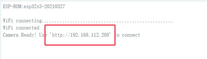
- Use the browser (the device with hotspot enabled) to open the IP address for serial port printing
- Click Start Stream to see the image of the camera
Working with ESP-IDF
This chapter introduces setting up the ESP-IDF environment setup, including the installation of Visual Studio and the Espressif IDF plugin, program compilation, downloading, and testing of demos, to assist users in mastering the development board and facilitating secondary development. 
Environment Setup
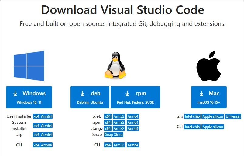
Download and Install Visual Studio
- Open the download page of VScode official website, choose the corresponding system and system bit to download
- After running the installation package, the rest can be installed by default, but here for the subsequent experience, it is recommended to check boxes 1, 2, and 3
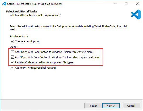
- After the first two items are enabled, you can open VSCode directly by right-clicking files or directories, which can improve the subsequent user experience.
- After the third item is enabled, you can select VSCode directly when you choose how to open it
Install Espressif IDF Plugin
- It is generally recommended to use Install Online. If online installation fails due to network factor, use Install Offline.
- For more information about how to install the Espressif IDF plugin, see Install Espressif IDF Plugin
- It is required to install ESP-IDF V5.4.0 or higher version.
Run the First ESP-IDF Demo
New Project
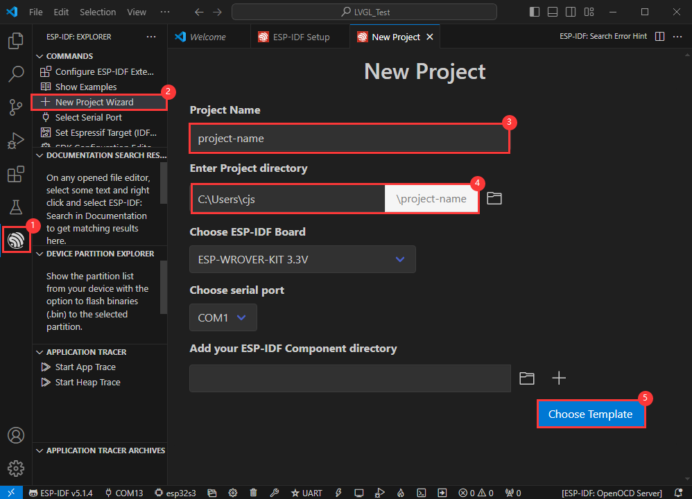

Create Demo
- Using the shortcut F1, enter esp-idf:show examples projects
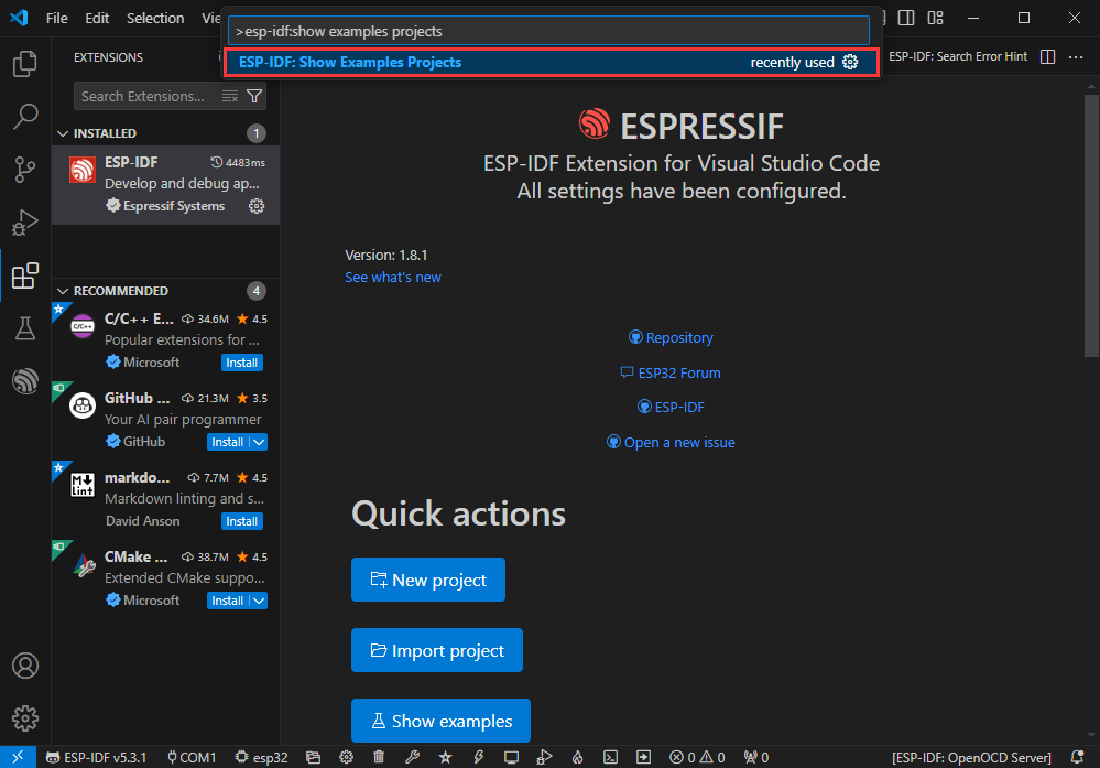
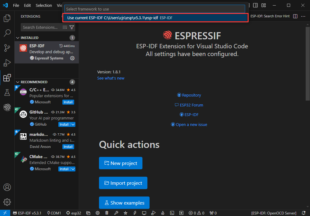
- Select your current IDF version
- Take the Hello world demo as an example
①Select the corresponding demo
②Its readme will state what chip the demo applies to (how to use the demo and the file structure are described below, omitted here)
③Click to create the demo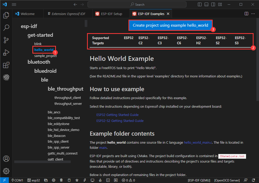
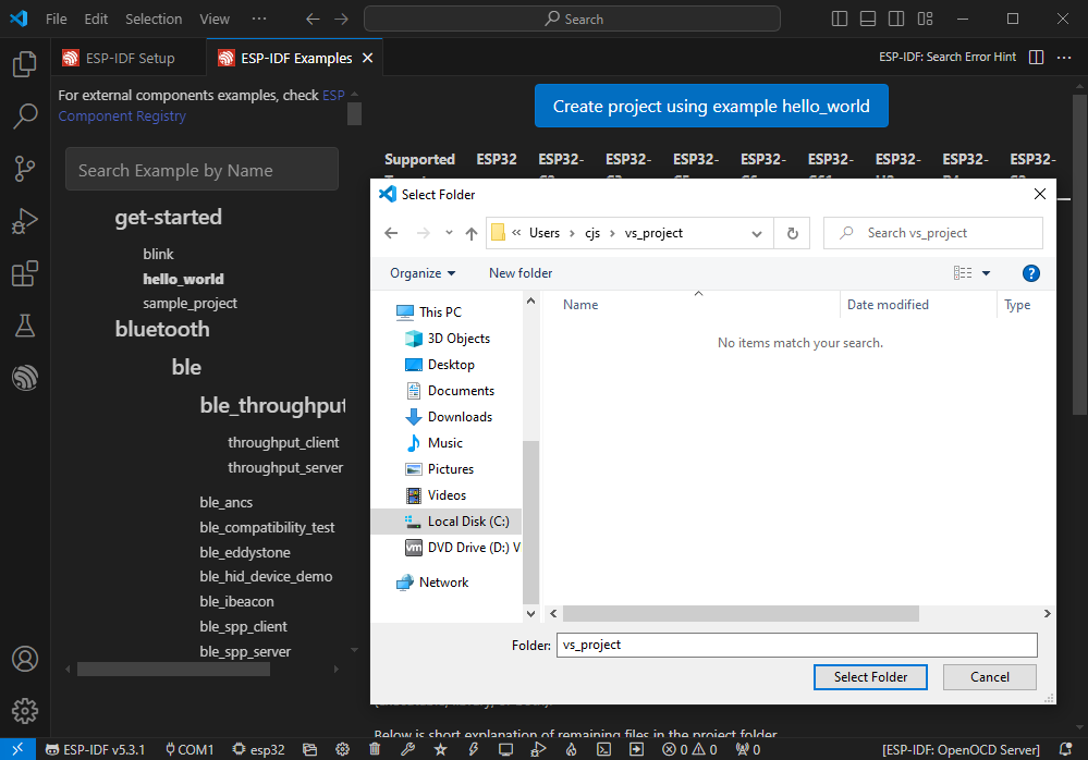
- Select the path to save the demo, and require that the demos cannot use folders with the same name
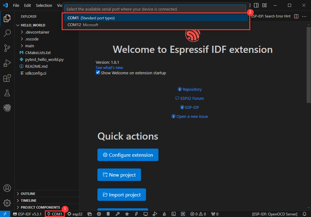
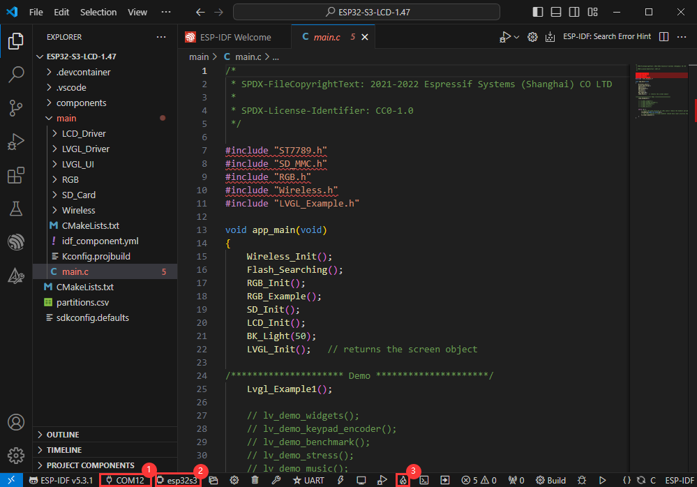
Modify COM Port
- The corresponding COM ports are shown here, click to modify them
- Please select the COM ports according to your device (You can view it from the device manager)
- In case of a download failure, please press the Reset button for more than 1 second or enter download mode, and wait for the PC to recognize the device again before downloading once more
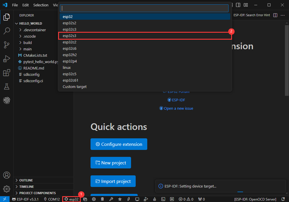
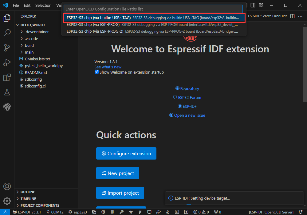
Modify Driver Object
- Select the object we need to drive, which is our main chip ESP32S3
- Choose the openocd path, it doesn't affect us here, so let's just choose one
Other Status Bar Functions
①.ESP-IDF Development Environment Version Manager, when our project requires differentiation of development environment versions, it can be managed by installing different versions of ESP-IDF. When the project uses a specific version, it can be switched to by utilizing it
②.Device flashing COM port, select to flash the compiled program into the chip
③.Select set-target chip model, select the corresponding chip model, for example, ESP32-P4-NANO needs to choose esp32p4 as the target chip
④.menuconfig, click it to Modify sdkconfig configuration file Project configuration details
⑤.fullclean button, when the project compilation error or other operations pollute the compiled content, you can clean up all the compiled content by clicking it
⑥.Build project, when a project satisfies the build, click this button to compile
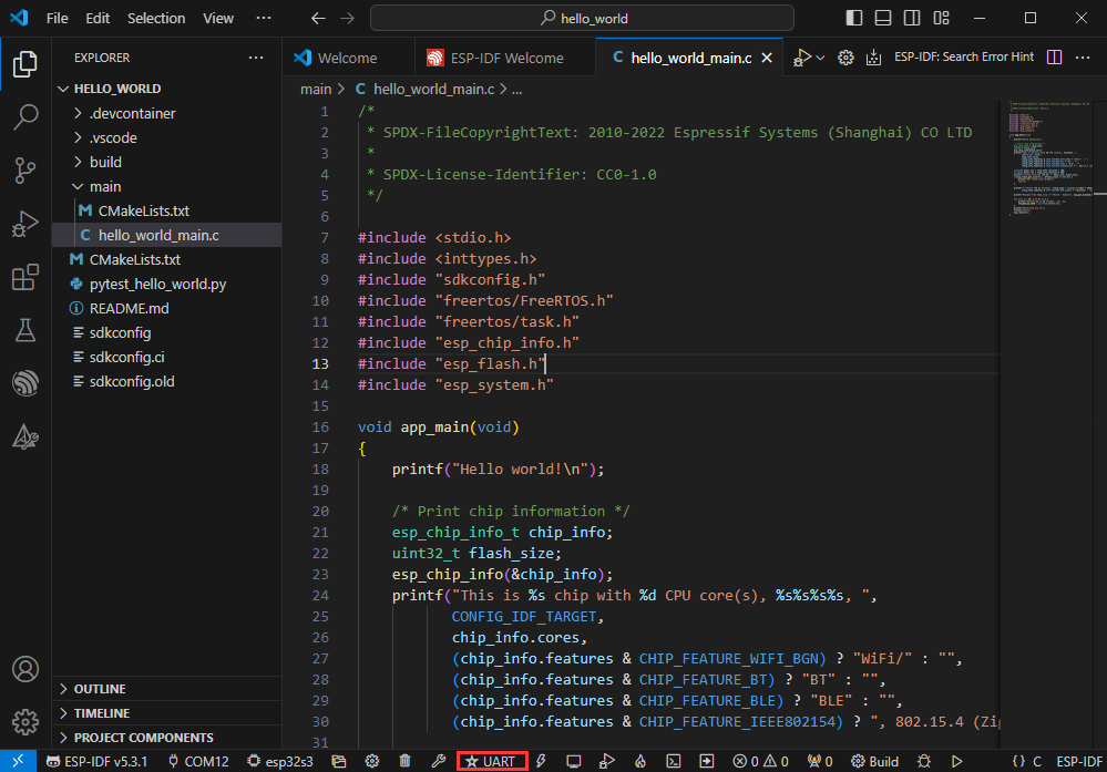
⑦.Current download mode, the default is UART
⑧.flash button, when a project build is completed, select the COM port of the corresponding development board, and click this button to flash the compiled firmware to the chip
⑨.monitor enable flashing port monitoring, when a project passes through Build --> Flash, click this button to view the log of output from flashing port and debugging port, so as to observe whether the application works normally
⑩.Debug
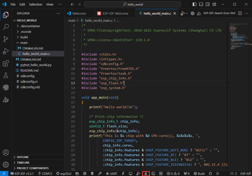
⑪.Build Flash Monitor one-click button, which is used to continuously execute Build --> Flash --> Monitor, often referred to as "little flame"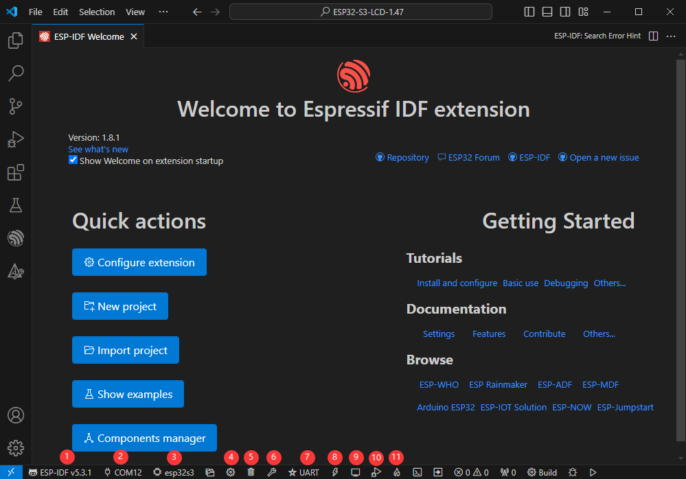
Compile, Flash and Serial Port Monitor
- Click on the all-in-one button we described before to compile, flash and open the serial port monitor
- It may take a long time to compile especially for the first time
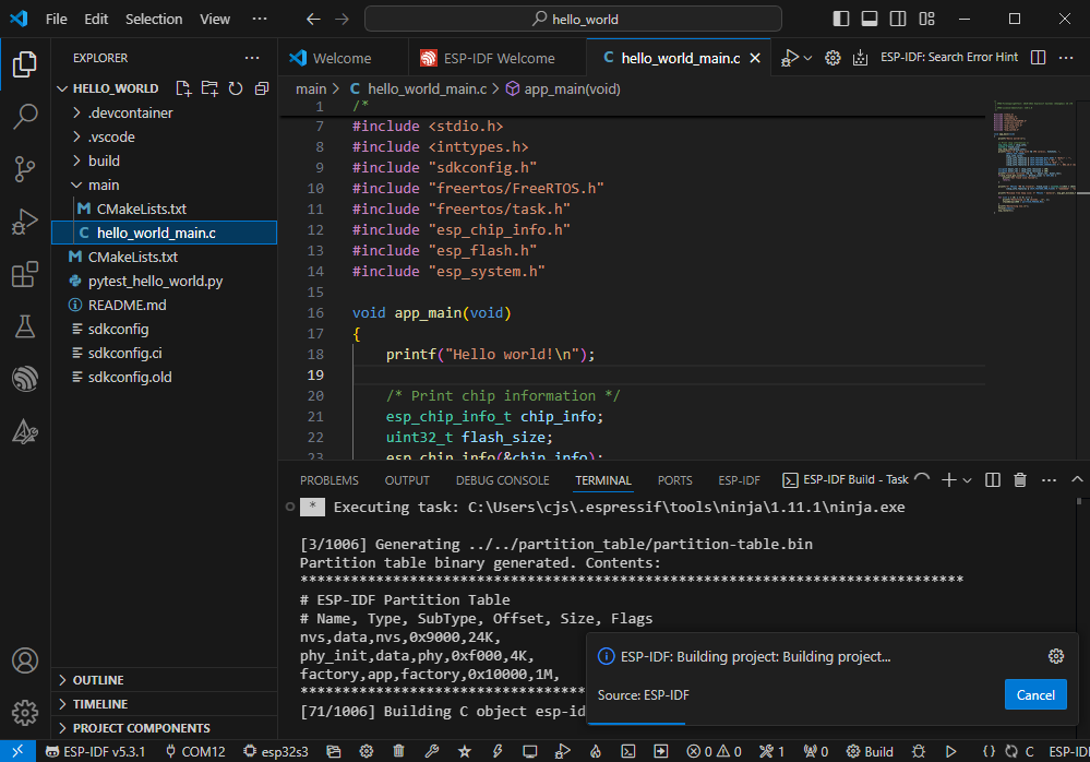
- During this process, the ESP-IDF may take up a lot of CPU resources, so it may cause the system to lag
- If it is the first time to flash the program for a new project, you will need to select the download method, and select UART
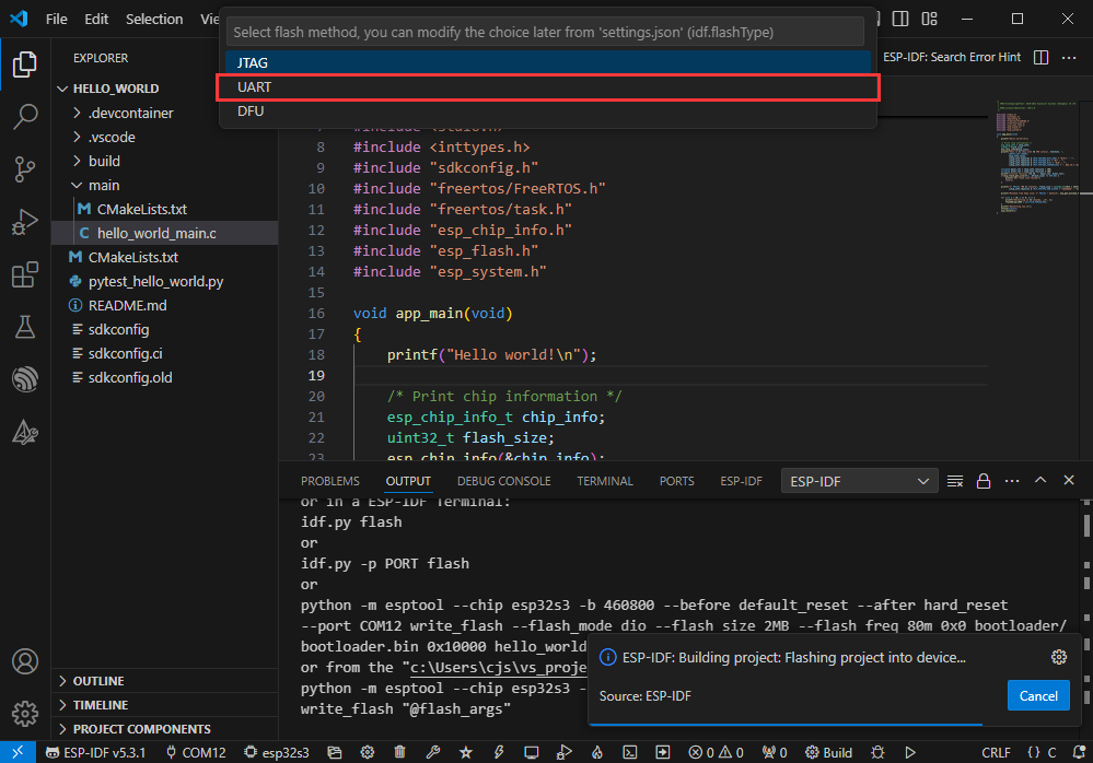
- This can also be changed later in the Download methods section (click on it to pop up the options)
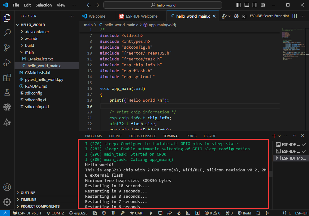
- As it comes with the onboard automatic download circuit, it can be downloaded automatically without manual operation
- After successful download, it will automatically enter the serial monitor, you can see the chip output the corresponding information and be prompted to restart after 10S
Use the IDF Demos
Open In the Software
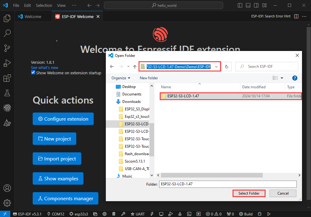
- Open VScode software and select the folder to open the demo
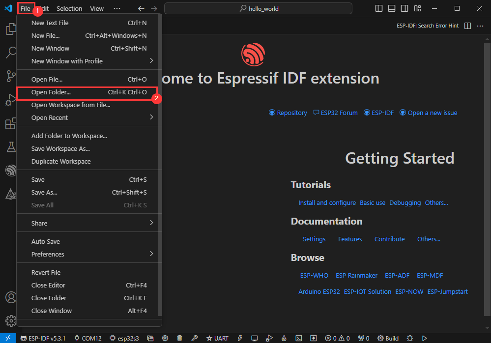
- Select the provided ESP-IDF example and click to select the file (located in the /Demo/ESP-IDF path under demo)
Open from Outside the Software
- Select the project directory correctly and open the project, otherwise it will affect the compilation and flashing of subsequent programs
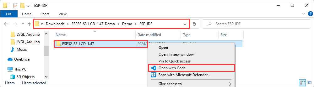
- After connecting the device, select the COM port and model, click below to compile and flash to achieve program control
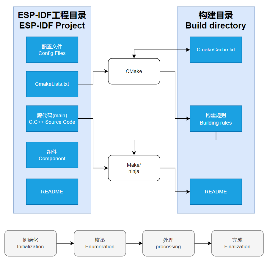
ESP-IDF Project Details
- Component: The components in ESP-IDF are the basic modules for building applications, each component is usually a relatively independent code base or library, which can implement specific functions or services, and can be reused by applications or other components, similar to the definition of libraries in Python development.
- Component reference: The import of libraries in the Python development environment only requires to "import library name or path", while ESP-IDF is based on the C language, and the importing of libraries is configured and defined through
CMakeLists.txt. - The purpose of CmakeLists.txt: When compiling ESP-IDF, the build tool
CMakefirst reads the content of the top-levelCMakeLists.txtin the project directory to read the build rules and identify the content to be compiled. When the required components and demos are imported into theCMakeLists.txt, the compilation toolCMakewill import each content that needs to be compiled according to the index. The compilation process is as follows:
- Component reference: The import of libraries in the Python development environment only requires to "import library name or path", while ESP-IDF is based on the C language, and the importing of libraries is configured and defined through
Demo

| Demo | Basic Description |
|---|---|
| 01_factory | Comprehensive demo |
| 02_qmi8658_example | Print the IMU data |
| 03_pcf85063_example | Print the data acquired by the RTC |
| 04_axp2101_example | Print the data of the power management chip |
| 05_lvgl_example | Run the official Demo UI of LVGL |
| 06_lvgl_image | Use lvgl to display images |
| 07_lvgl_image_sd | Use lvgl to display images from TF card |
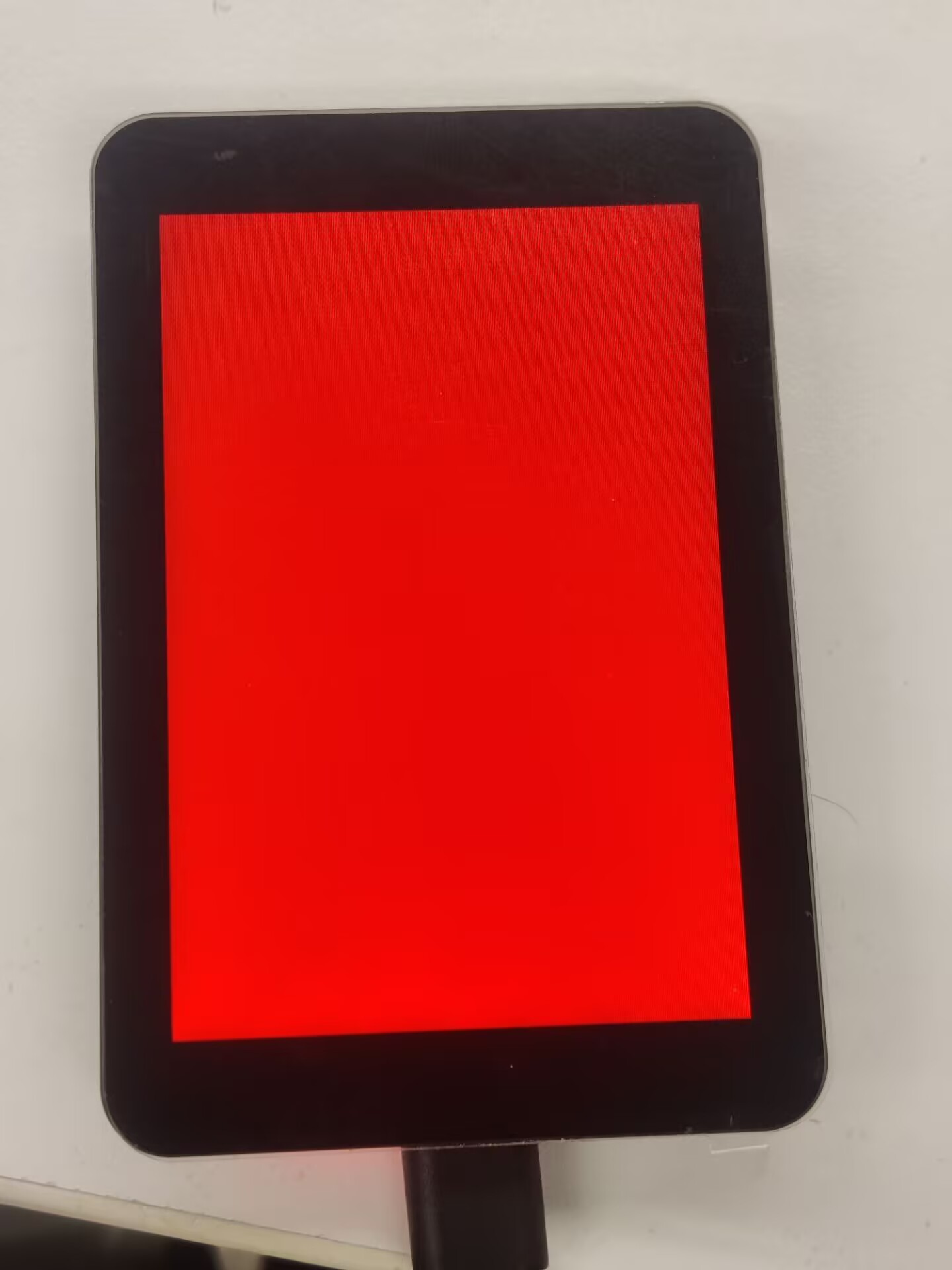
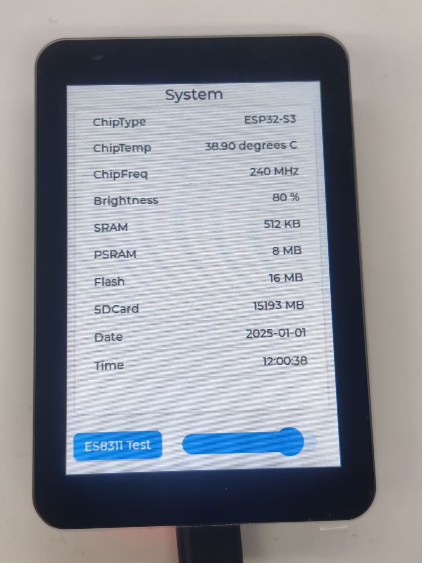
01_factory
【Demo description】
This demo is a comprehensive demo of ESP32-S3-Touch-LCD-3.5B, which is also the default demo flashed at factory.
【Result demonstration】
- Touch test, swipe your finger on the screen to display its trajectory, press X to exit the touch test
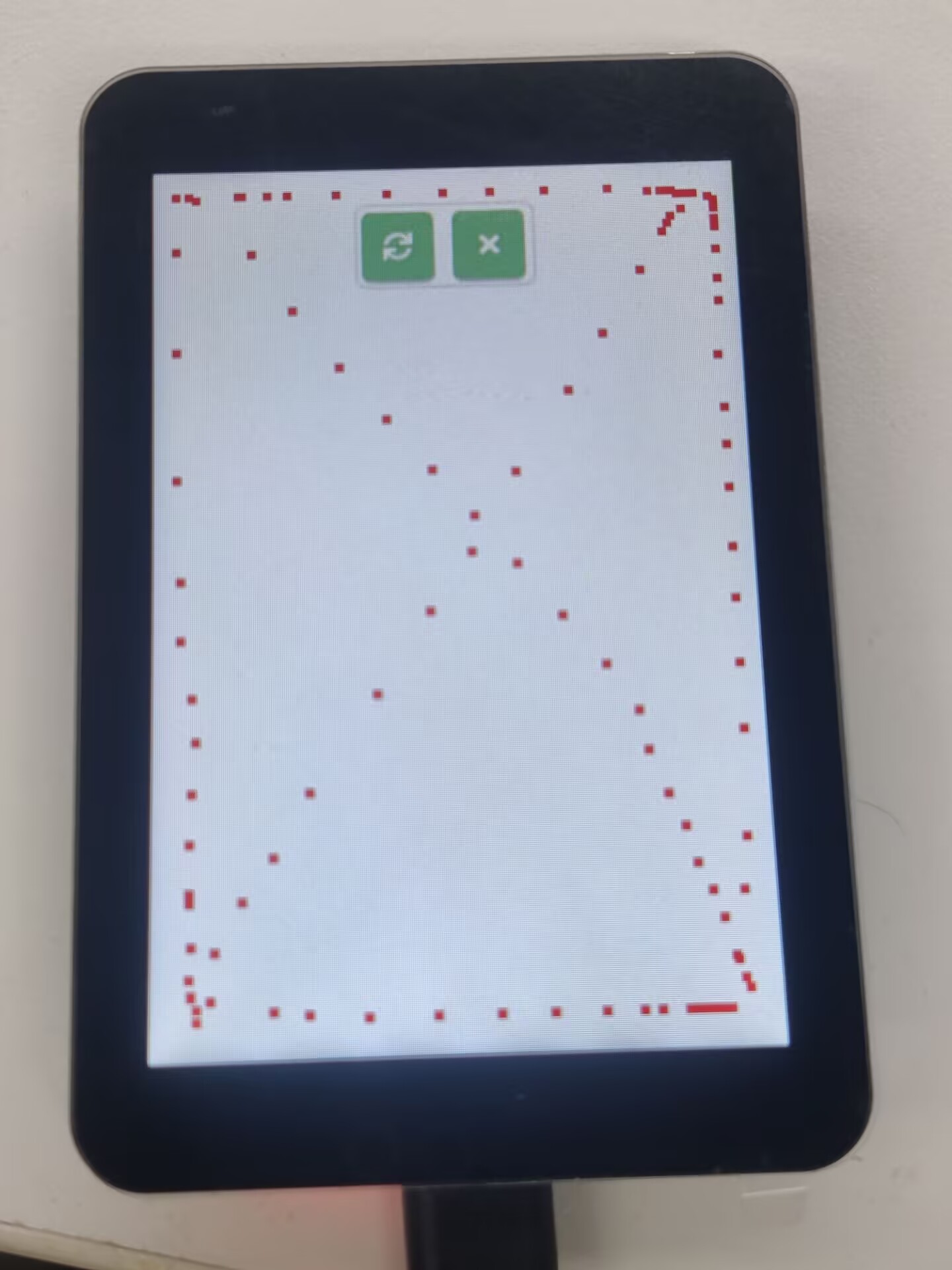
- Switch between interfaces by swiping left and right.
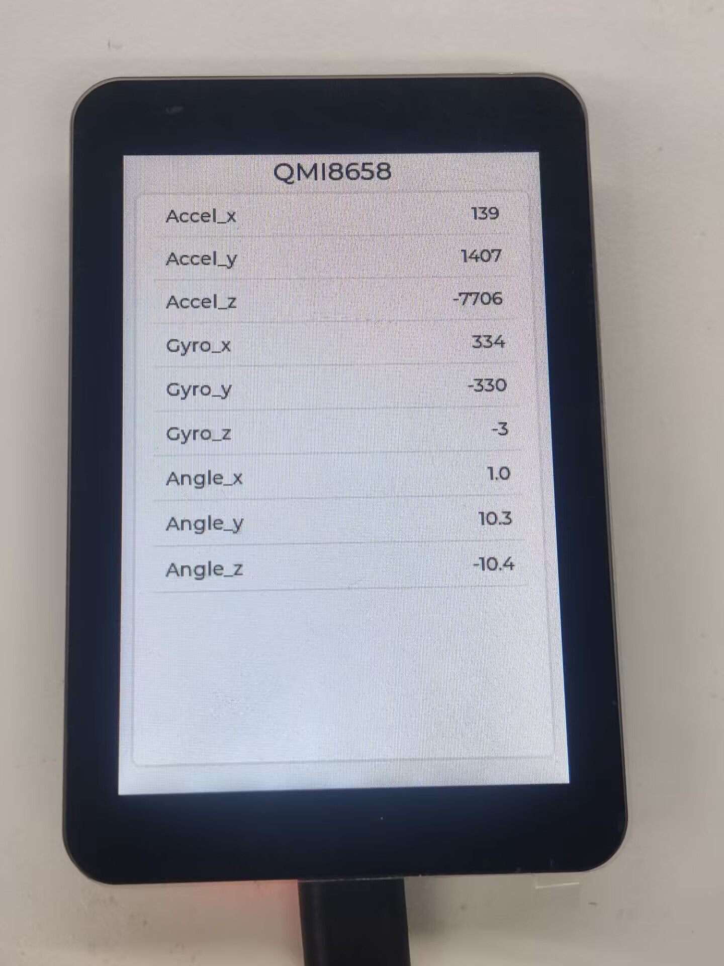
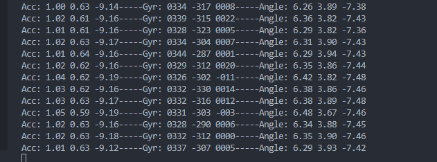
02_qmi8658_example
【Demo description】
This demo demonstrates the ESP32-S3-Touch-LCD-3.5B driving QMI8658 to obtain and print the temperatures of Accel, Gyro, and IMU.
【Code analysis】
- Initialize and start the test program
    i2c_master_bus_handle_t i2c_bus_handle = bsp_i2c_init();
    bsp_qmi8658_init(i2c_bus_handle);
    bsp_qmi8658_test();
【Result demonstration】
- Nothing will be shown on the screen
- Open the serial port monitor
03_pcf85063_example
【Demo description】
This demo demonstrates the ESP32-S3-Touch-LCD-3.5B driving the PCF85063 to set time, date, and retrieve time.
【Code analysis】
- Initialize and start the test program
    i2c_master_bus_handle_t i2c_bus_handle = bsp_i2c_init();
    bsp_pcf85063_init(i2c_bus_handle);
    bsp_pcf85063_test();
【Result demonstration】
- Nothing will be shown on the screen
- Open the serial port monitor
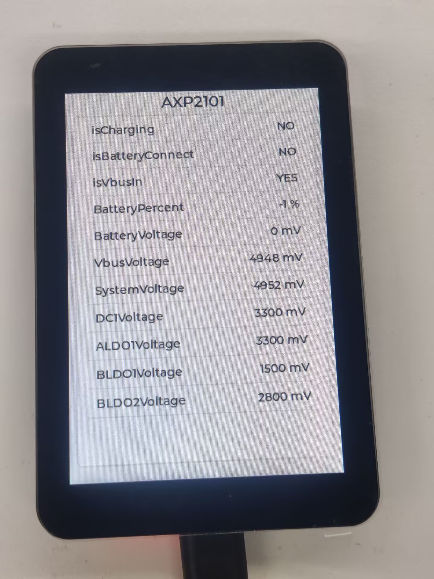
04_axp2101_example
【Demo description】
This demo demonstrates using XPowers to drive AXP2101 and print data via serial port.
【Code analysis】
- Initialize
    i2c_master_bus_handle_t i2c_bus_handle = bsp_i2c_init();
    bsp_axp2101_init(i2c_bus_handle);
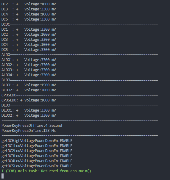
【Result demonstration】
- Nothing will be shown on the screen
- Open the serial port monitor
05_lvgl_example
【Demo description】
This demo demonstrates how to use ESP32-S3-Touch-LCD-3B to run the lvgl demos.
【Code analysis】
- Select the lvgl demos to run
        // lv_demo_benchmark();
        // lv_demo_music();
        lv_demo_widgets();
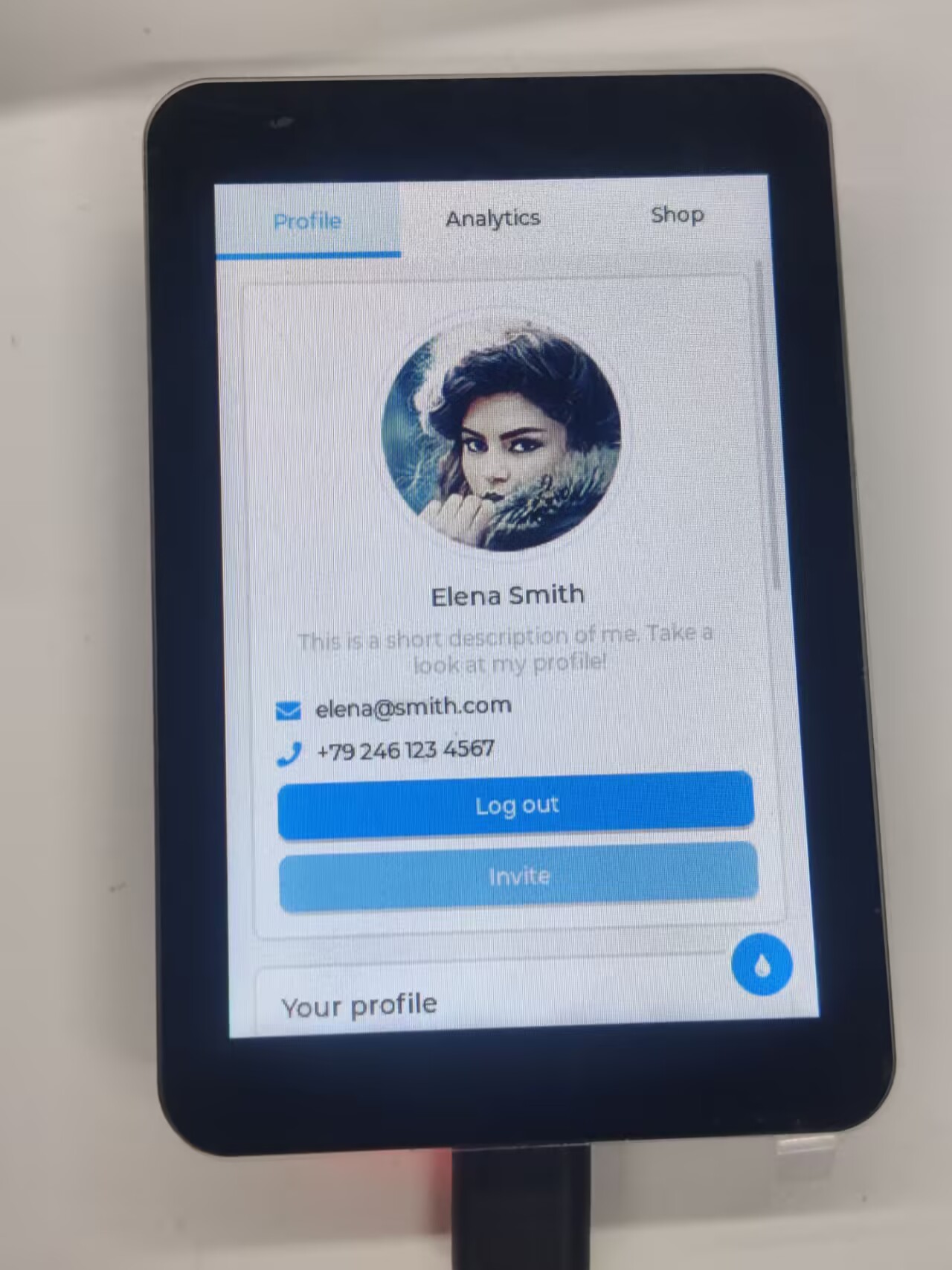
【Result demonstration】
- It can be operated by touch
06_lvgl_image
【Demo description】
This demo demonstrates that ESP32-S3-Touch-LCD-3.5B runs the lvgl to display images.
【Hardware connection】
- Connect the board to the computer
【Preparation】
- Open lvgl Image Converter website
- Import the image images/image_1.jpg and convert it, the image_1.c file will be generated
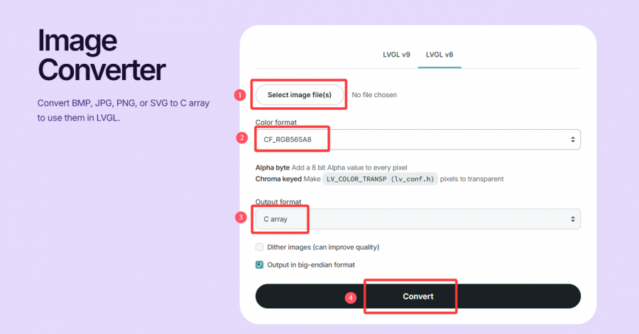
- Copy image_1.c to the main folder
- Add "image_1.c" to the CMakeLists.txt in the main folder
idf_component_register(SRCS "main.cpp" "image_1.c"
                    INCLUDE_DIRS ".")
- Add the following code to main.c to declare the image
LV_IMG_DECLARE(image_1);
- Set the image to be displayed
lv_img_set_src(img, &image_1);
【Result demonstration】
07_lvgl_image_sd
【Demo description】
This demo demonstrates how ESP32-S3-Touch-LCD-3.5B uses lvgl to display images from a TF card, supporting formats such as jpg, bmp, png, bin, etc.
【Hardware connection】
- Connect the board to the computer
- Insert the TF card into the card slot
【Preparation】
- Insert the TF card into the computer
- Copy the images folder of this project to the root directory of the TF card
- Insert the TF card into ESP32-S3-Touch-LCD-3.5B
【Result demonstration】

Flash Firmware Flashing and Erasing
- The current demo provides test firmware, which can be used to test whether the onboard device functions properly by directly flashing the test firmware
- bin file path:
..\ESP32-S3-Touch-LCD-3.5B-Demo\Firmware
Resources
Schematic Diagram
Project Diagram
Demo
Datasheets
ESP32-S3
Other Components
- QMI8658 Datasheet
- PCF85063 Datasheet
- AXP2101 Datasheet
- ES8311 Datasheet
- ES8311 User Guide
- AXS15231B Datasheet
Softwares
- Zimo221 Chinese character conversion software
- Image2Lcd image bitmap conversion software
- flash_download_tool_3.9.7
Other Resource Links
- Image bitmap conversion tutorial
- Font library conversion tutorial
- MicroPython official documentation
- ESP32 Arduino Core's documentation
- arduino-esp32
- ESP-IDF
FAQ
Question: What platforms does the AI large model example of speech dialog support?
The product is equipped with ES8311 audio codec chip, onboard speaker, and SMD microphone. And it can achieve voice dialogue function;
At present, the access to various platforms has been verified, and mainstream platforms such as Doubao, ERNIE Bot , and ChatGPT are supported. The demos will gradually be opened up to ESP32-AIChats
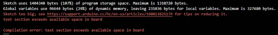
Question: Why did the compilation fail?
When the project fails to be compiled, check the development environment.
- Arduino IDE compiling the project shows the situation in the image, you need to modify Partition Scheme->16M Flash(3MB APP/9.9MB FATFS)。
- When the ESP-IDF project compilation fails, delete the build, managed_components, and dependencies.lock, and then compile again. If the error persists, check whether the ESP-IDF version and the CMakeList.txt in the project directory are correctly recognized
Question: Why does the module keep resetting?
In this case, due to the crash of the program, the USB cannot work normally, you can press and hold the BOOT button and then power on, at this time, the module can enter the download mode to flash the firmware (program) to solve the situation.
Question: How to deal with the first compilation of the program being extremely slow?
In the Arduino IDE, the first compilation loads and compiles all the dependencies, so it's normal for the first compilation task to be time-consuming. Just wait patiently
Question: How to handle the display "waiting for download..." on the serial port after successfully ESP-IDF flashing?
Power it on again
Question: How to measure the battery voltage of this product?
This product has an on-board AXP2101, which can measure all kinds of battery data, such as: chip temperature, whether it is charged, whether it is connected to the power supply, charging status, battery voltage, charging voltage, battery power, etc.
Question: This product measures the percentage of battery remaining capacity. Why does the result fluctuate greatly?
The battery capacity measurement of the AXP2101 is based on battery voltage, but battery capacity does not vary linearly, so large percentage fluctuations may occur during measurement. Especially in the case of plugging and unplugging chargers, load changes, or battery aging, the fluctuations become more noticeable. The measured percentages are for reference only, and the actual voltage is used as a measure of capacity.
Question: Can you provide the 3D file for the casing?
It is not provided.
Question: Can both buttons of this product be programmed for use?
Yes, the two buttons of this product are BOOT and PWR. The functions are as follows:
1. BOOT: Press and then power on, and the development board enters download mode (commonly used when the program freezes or the USB GPIO is occupied); under normal working conditions, the GPIO0 can detect the high and low level of the button to determine the action, and the low level is pressed, which can recognize click, double-click, multi-click, and long-press actions.
2.PWR: In the power-on state, press and hold for 6s to power off, in the power-off state (power off to charge the battery), click to power on; Under normal working conditions, the action can be judged by the high and low levels of the EXIO6 detection buttons of the extended IO, and the high level is pressed, which can identify the actions of single click, double click, multiple click and long press (long press should not exceed 6s, otherwise the power will be turned off).
Question: Does this product support Bluetooth?
The core chip of this product is ESP32-S3R8, which supports wireless communication functions such as 2.4GHz WiFi and Bluetooth LE 5, and has an onboard SMD antenna, and the antenna gain has been adjusted to the optimum, which can support the use of Bluetooth and WiFi. For details, please refer to ESP32-S3 datasheet
Question: Does this product support Chinese display?
This product uses ESP32-S3R8 as the core, connects the screen via SPI protocol, fully supports Chinese display, but requires meeting the following conditions:
1. Character encoding support is required, and strings that support UNICODE-8 encoding can be rendered to the screen
2. Font library support
3. Display library support, LVGL or Arduino_GFX are supported
Question: What chip is used for the screen of this product?
AXS15231B display driver IC
Question: Is this product waterproof?
It is not waterproof and should be kept dry when used
Question: How to check the COM port I use?
Windows system:
①View through Device Manager: Press the Windows + R keys to open the "Run" dialog box; Input devmgmt.msc and press Enter to open Device Manager; Expand the "Port (COM and LPT)" section, here it will list all the COM ports and their current status.
②Use the command prompt to view: Open the Command Prompt (CMD); enter the mode command, which will display status information for all COM ports.
③Check hardware connections: If you have already connected external devices to the COM port, the device usually occupies a port number, which can be determined by checking the connected hardware.
Linux system:
①Use the dmesg command to view: Open the terminal.
①Use the ls command to view: Enter ls /dev/ttyS* or ls /dev/ttyUSB* to list all serial port devices.
③Use the setserial command to view: Enter setserial -g /dev/ttyS* to view the configuration information of all serial port devices.
Question: Why is there no output from the monitor after running the code, even though the code is correct and successfully flashed?
The Type-C flashing and debugging port of ESP32-S3-Touch-LCD-3.5B is directly output from ESP32-S3 USB. In the Arduino IDE development environment, it supports printf function for printing and output. If you want to support Serial function for printing and output, you need to enable USB CDC On Boot function or HWCDC declaration. For this, please refer to the demonstration in the demo. ESP-IDF usually uses ESP_LOGD and ESP-ERROR_CECK for printing output.
Support
Monday-Friday (9:30-6:30) Saturday (9:30-5:30)
Email: services01@spotpear.com
[Tutorial Navigation]
- Overview
- Usage Instructions
- Working with Arduino
- Working with ESP-IDF
- Environment Setup
- Run the First ESP-IDF Demo
- New Project
- Create Demo
- Modify COM Port
- Modify Driver Object
- Other Status Bar Functions
- Compile, Flash and Serial Port Monitor
- Use the IDF Demos
- Demo
- Flash Firmware Flashing and Erasing
- Resources
- FAQ
- Question: What platforms does the AI large model example of speech dialog support?
- Question: Why did the compilation fail?
- Question: Why does the module keep resetting?
- Question: How to deal with the first compilation of the program being extremely slow?
- Question: How to handle the display "waiting for download..." on the serial port after successfully ESP-IDF flashing?
- Question: How to measure the battery voltage of this product?
- Question: This product measures the percentage of battery remaining capacity. Why does the result fluctuate greatly?
- Question: Can you provide the 3D file for the casing?
- Question: Can both buttons of this product be programmed for use?
- Question: Does this product support Bluetooth?
- Question: Does this product support Chinese display?
- Question: What chip is used for the screen of this product?
- Question: Is this product waterproof?
- Question: How to check the COM port I use?
- Question: Why is there no output from the monitor after running the code, even though the code is correct and successfully flashed?
- Support