


- sales/support
Google Chat:---
- sales
+86-0755-88291180
- sales01
sales@spotpear.com
- sales02
dragon_manager@163.com
- support
tech-support@spotpear.com
- CEO-Complaints
zhoujie@spotpear.com
- Only Tech-Support
WhatsApp:13246739196
- Purchase/Shipping/Refund
WhatsApp:13424403025
- HOME
- >
- ARTICLES
- >
- Common Moudle
- >
- Power
Modbus-RTU-Relay User Guide
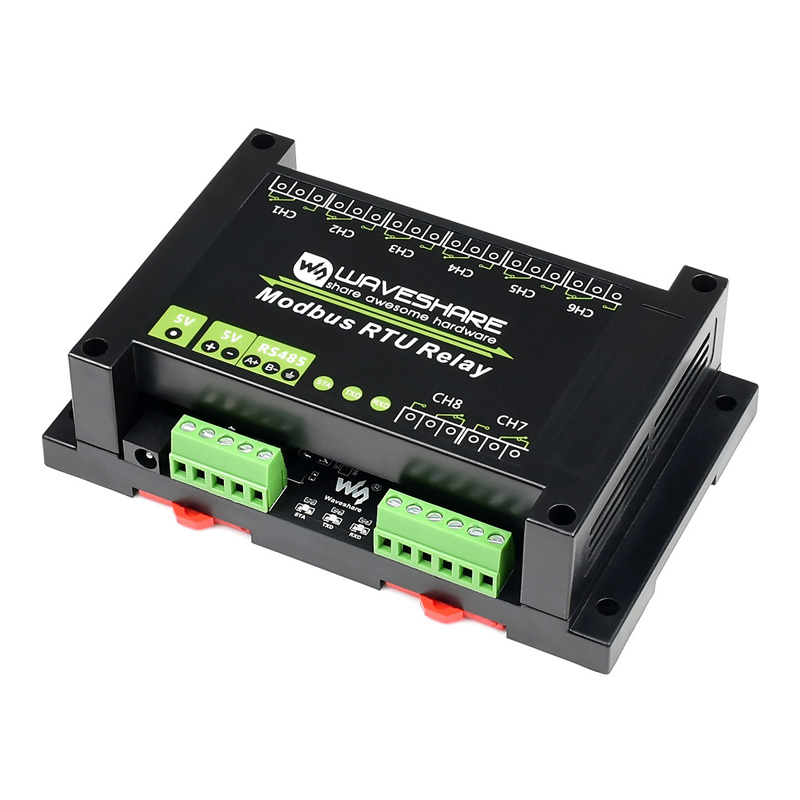
Overview
Electrical Safety Precautions
- This product should be operated and used by professional electricians or technical personnel. During use, please ensure electrical safety and take protective measures such as anti-leakage and insulation.
- Before installing, maintaining, or replacing relay device, make sure to turn off the power and unplug the device.
- Do not attempt to dismantle relay device to avoid damaging the device or risking electric shock.
- Please properly install and place the relay device. Avoid using it in damp, overly hot, or flammable environments to prevent safety accidents due to improper installation or use.
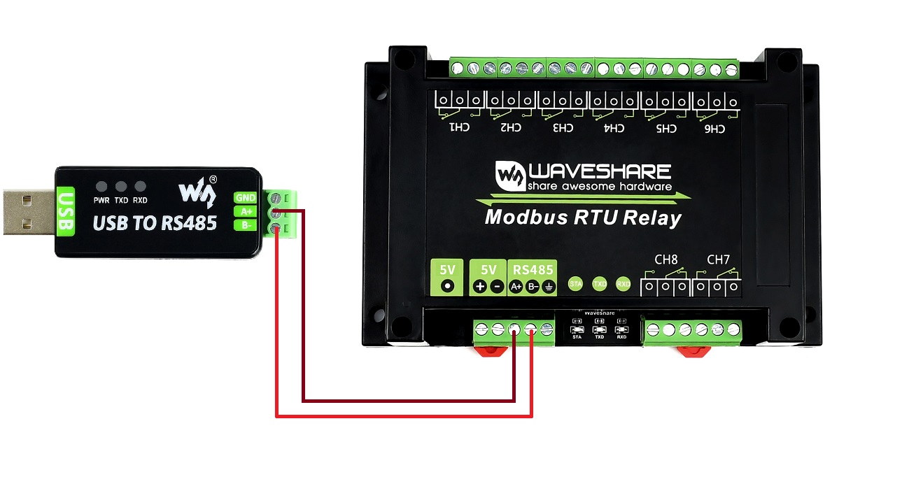
Hardware Connection
- Connect the USB TO 485 to the target boards via cables, A-A and B-B connected as shown below:
Example Demonstration
SSCOM Serial Port Debugging Assistant
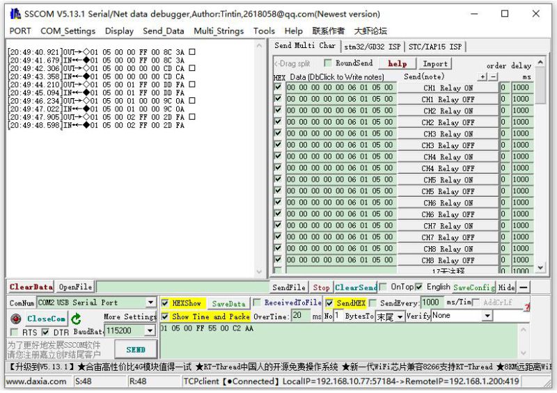
- Download SSCOM Serial port debugging assistant and open it on the computer, open the corresponding port number, and set the baud rate as 9600. Click Multi-Strings to open the Send Multi-Char window, and click the function to send the corresponding command.
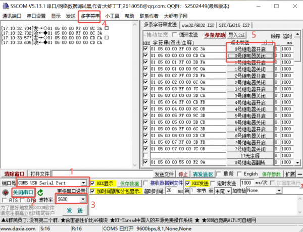
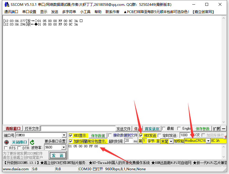
- If you need to send other commands, choose SendHEX. For checksum validation, select ModbusCRC16. After entering the first six bytes of the command, clicking SEND will automatically add the CRC check code.
- For detailed control commands, please see the development protocol.
From September 2024, the V3 development protocol will be adopted, which will be compatible with the V2 version, and some new features will be added.
Modbus Poll Software
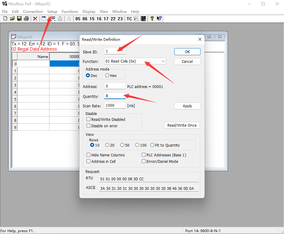
- It is not convenient to use the SSCOM software for observing the data, you can select Modbus Poll software to read the data. Download and install the Modbus Poll software.
- Open the software, select Setup->Read/Write Definition, select the actual device address for Slave ID, select 01 Read Coils function code for Function, and change Quantity to 8 channels. Click OK to confirm.
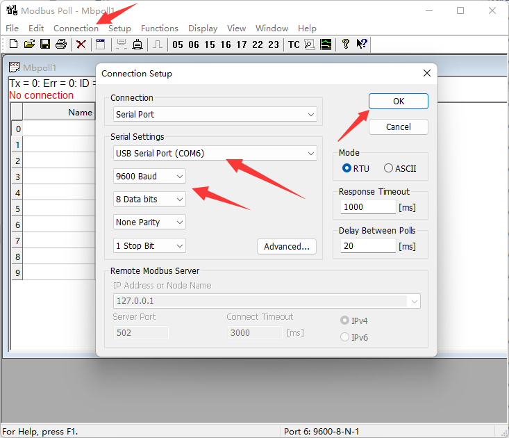
- Select Connection->Connect..., choose the corresponding serial port, set the baud rate to 9600, and select 8 Data bits and None Parity. Click OK to connect.
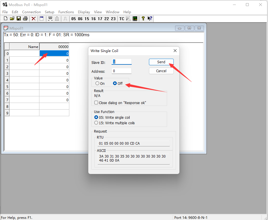
- After the connection is normal, you can check the current relay status. Select the corresponding channel, then double-click the status value to pop up the send page. Choose On or Off, then click Send to control the relay opening and closing.
Demo Test
Note: RS485 can not be directly connected to the serial port of the Raspberry Pi, otherwise it may burn the device, you need to add 485 level conversion. For Raspberry Pi, it is recommended to work with the RS485 CAN HAT module. For NUCLEO-F103RB and Arduino, it is recommended to work with the RS485 CAN Shield module.
Raspberry Pi
Open the Raspberry Pi terminal and enter the following command to enter the configuration interface
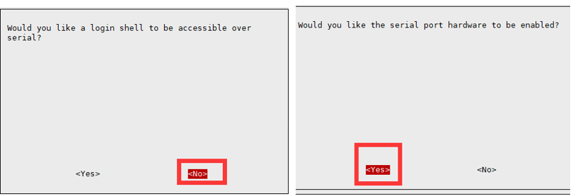
sudo raspi-config
Select Interfacing Options -> Serial, disable shell access, and enable the hardware serial port
Then restart Raspberry Pi:
sudo reboot
Open the /boot/config.txt file, find the following configuration statement to enable the serial port, if not, you can add it to the end of the file.
enable_uart=1
For Raspberry Pi 3B users, the serial port is used for Bluetooth and needs to comment out:
#dtoverlay=pi3-miniuart-bt
Then restart Raspberry Pi:
sudo reboot
Insert the RS485 CAN HAT into the Raspberry Pi, and connect the Modbus RTU Relay module to the RS485 CAN HAT through A and B.
If you are using other 485 devices, make sure to connect A-A, B-B.
Run the following commands to run the demo:
sudo apt-get install unzip
wget https://files.waveshare.com/wiki/Modbus-RTU-Relay/Modbus_RTU_Relay_Code.zip
unzip Modbus_RTU_Relay_Code.zip
cd Modbus_RTU_Relay_Code/Python3
sudo python3 main.py
STM32
Note: The STM32 demo is based on the NUCLEO-F103RB and RS485 CAN Shield module.
1. Download Demo, find the STM32 project file Modbus Relay.uvprojx in the path Modbus_RTU_Relay_Code\STM32\MDK-ARM, and double-click to open the STM32 project file. Note that you should ensure Keil5 software is installed on your computer before using it.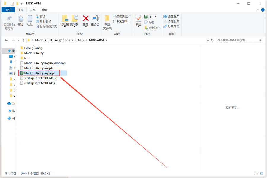
2. Connect the STM32 to a computer via the STM32 download and debug probe. Compile and download the demo to the STM32.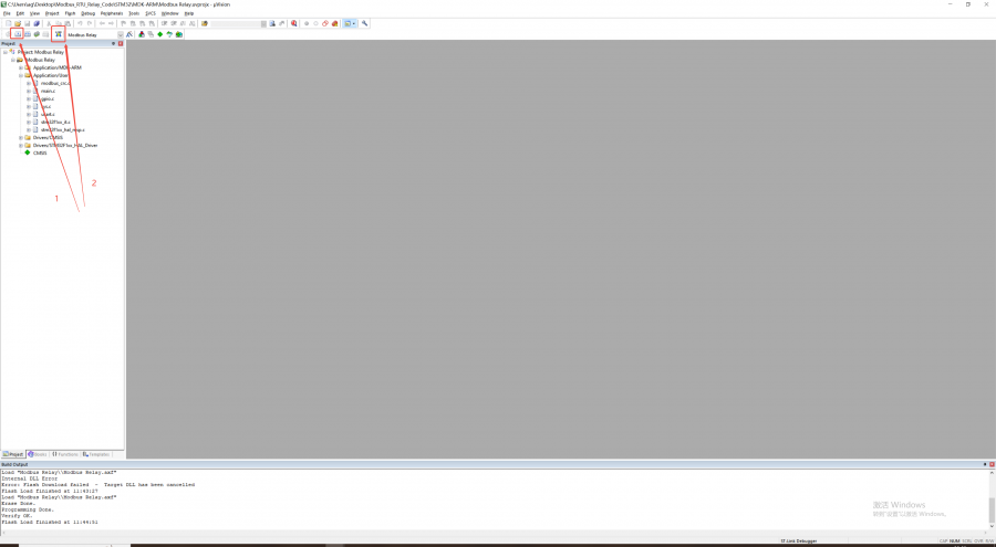
3. Install the RS485 CAN Shield module on the STM32. Connect the RS485_A on the RS485 CAN Shield module to the RS485_A on the Modbus RTU Relay via a wire, and connect the RS485_B on the RS485 CAN Shield module to the RS485_B on the Modbus RTU Relay via a wire. Then power on the Modbus RTU Relay and the STM32 sequentially.
4. After powering on, the serial port will output the sent commands, which can be observed using a serial port assistant. At the same time, the relays will turn on in sequence (e.g., 1→2→3→4), and after all of them are turned on, they will then turn off in sequence (e.g., 1→2→3→4). You can observe whether the relay is normally engaged through the LED indicator light.
Arduino
Note: The Arduino demo is based on the UNO PLUS and RS485 CAN Shield module.
1. Download Demo, find the Arduino project file Modbus_RTU_Relay.ino in the path Modbus_RTU_Relay_Code\Arduino\Modbus_RTU_Relay, and double-click to open the Arduino project file. Note that you should ensure Arduino IDE software is installed on your computer before using it.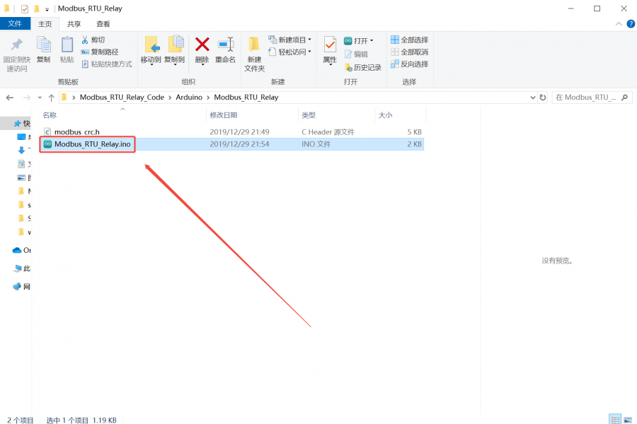
2. Connect the Arduino to the computer via a USB cable. In the Arduino IDE software, select the Arduino board model under Tools->Board. Choose the COM port that the Arduino is connected to under Tools->Port.
3. After seeing the prompt to connect to the computer in the lower right corner, click to compile and flash the program, and wait for the flashing to complete.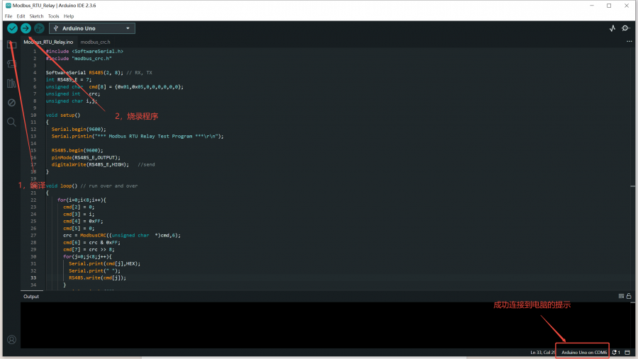
4. Install the RS485 CAN Shield module on the Arduino. Connect the RS485_A on the RS485 CAN Shield module to the RS485_A on the Modbus RTU Relay via a wire, and connect the RS485_B on the RS485 CAN Shield module to the RS485_B on the Modbus RTU Relay via a wire. Then power on the Modbus RTU Relay and the Arduino sequentially.
5. After powering on, the serial port will output the sent commands, which can be observed using a serial port assistant. At the same time, the relays will turn on in sequence (e.g., 1→2→3→4), and after all of them are turned on, they will then turn off in sequence (e.g., 1→2→3→4). You can observe whether the relay is normally engaged through the LED indicator light.
Note: The data in the figure below is in ASCII code containing spaces and line breaks, and is not the actual data sent.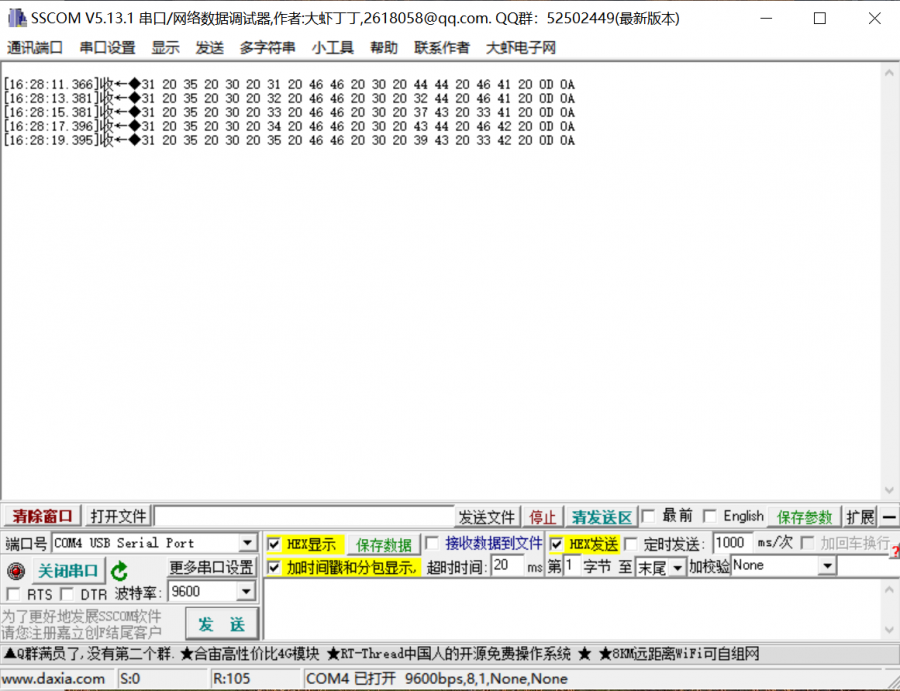
PLC
Note: The PLC demo is based on SIMATIC S7-200 SMART.
1. Download Demo, find the PLC project file modbus_rtu.smart in the path Modbus_RTU_Relay_Code\PLC, and double-click to open the PLC project file. Note that you should ensure STEP 7-MicroWIN SMART software is installed on your computer before using it.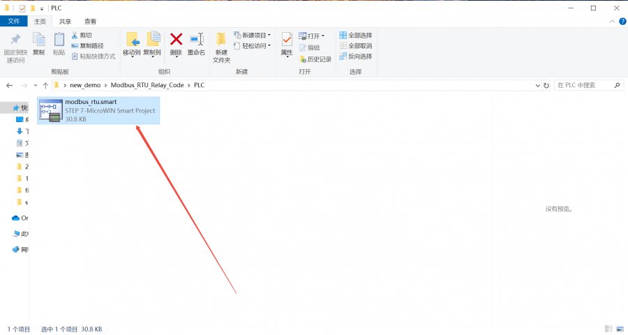
2. Connect the PLC to the computer via a network cable. Click to download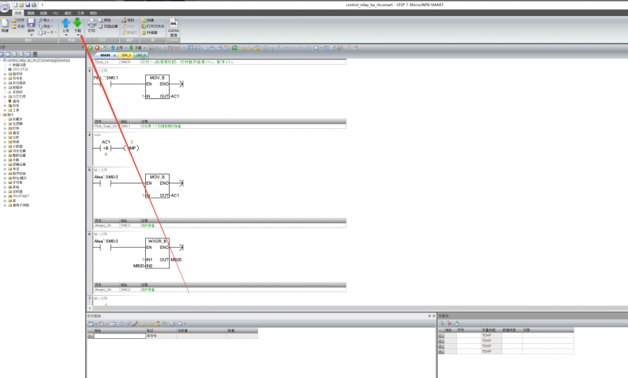
3. Select the communication interface in the communication popup, find your device, and click Confirm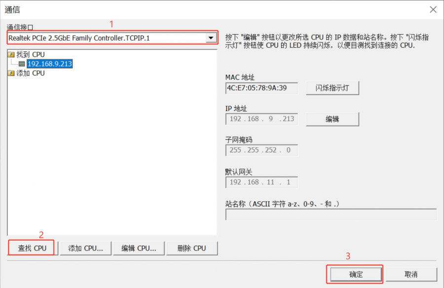
4. In the download pop-up window, check the boxes for program blocks, data blocks, and system blocks, and then click Download.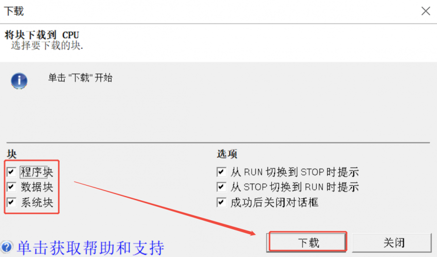
5. Connect the 485_A on the PLC module to RS485_A on the Modbus RTU Relay with a wire, and connect the 485_B on the PLC module to RS485_B on the Modbus RTU Relay with a wire. Then power on the Modbus RTU Relay.
6. After powering on the Modbus RTU Relay, in the STEP 7-MicroWIN SMART software, find the "PLC" tab in the upper menu bar, switch to this tab, and click the green "RUN" button in the lower "Operation" area to perform the operation to make the PLC enter the running state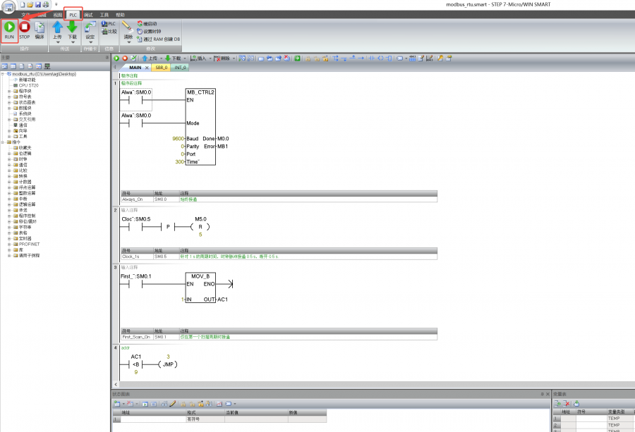
7. After the PLC runs, the relays will turn on in sequence (e.g., 1→2→3→4), and after all of them are turned on, they will then turn off in sequence (e.g., 1→2→3→4). You can observe whether the relay is normally engaged through the LED indicator light.
Development Protocol V3
Function Code Introduction
| Function Code | Description | Note |
|---|---|---|
| 01 | Read coil status | Read relay status |
| 03 | Read holding register | Read the address and version |
| 05 | Write single coil | Write single relay |
| 06 | Write single register | Set the baud rate and address |
| 0F | Write multiple coils | Write all relays |
Register Address Introduction
| Address (HEX) | Address storage content | Register value | Permission | Modbus Function Code |
|---|---|---|---|---|
| 0x0000 …… 0x0007 | Channels 1~8 relay addresses | 0xFF00: relay on 0x0000: relay off 0x5500: relay toggle | Read/Write | 0x01, 0x05, 0x0F |
| 0x00FF | Control all relays | 0xFF00: all relays on 0x0000: all relays off 0x5500: all relays toggle | Write | 0x05 |
| 0x0100 …… 0x0107 | Channels 1~8 relays toggle | 0xFF00: relay toggle 0x0000: relay unchanged | Write | 0x05, 0x0F |
| 0x01FF | All relays toggle | 0xFF00: all relays toggle 0x0000: all relays unchanged | Write | 0x05 |
| 0x0200 …… 0x0207 | Channels 1~8 relays flash on | Delay time: data*100ms Value: 0x0007, delay time: 7*100MS = 700MS | Write | 0x05 |
| 0x0400 …… 0x0407 | Channels 1~8 relays flash off | Delay time: data*100ms Value: 0x0007, delay time: 7*100MS = 700MS | Write | 0x05 |
| 4x2000 | UART Parameter | The high eight bits indicate the parity mode: 0x00~0x02 The low eight bits indicate the baud rate mode: 0x00~0x07 | Read/Write | 0x03, 0x06 |
| 4x4000 | Device Address | Directly store Modbus address Device address: 0x0001-0x00FF | Read/Write | 0x03, 0x06 |
| 4x8000 | Software Version | Converting to decimal and then shifting the decimal point two places to the left will represent the software version 0x0064 = 100 = V1.00 | Read | 0x03 |
Modbus RTU Command Introduction
Control Single Relay
Send code: 01 05 00 00 FF 00 8C 3A
| Field | Description | Note |
|---|---|---|
| 01 | Device Address | 0x00 indicates the broadcast address, 0x01-0xFF indicates the device address |
| 05 | 05 Command | Relay control |
| 00 00 | Address | The register address of the relay to be controlled, 0x0000-0x0007 |
| FF 00 | Command | 0xFF00: relay on; 0x0000: relay off; 0x5500: relay toggle |
| 8C 3A | CRC16 | The CRC16 checksum of the first 6 bytes of data |
Return code: 01 05 00 00 FF 00 8C 3A
| Field | Description | Note |
|---|---|---|
| 01 | Device Address | 0x00 indicates the broadcast address, 0x01-0xFF indicates the device address |
| 05 | 05 Command | Relay control |
| 00 00 | Address | The register address of the relay to be controlled, 0x0000-0x0007 |
| FF 00 | Command | 0xFF00: relay on; 0x0000: relay off; 0x5500: relay toggle |
| 8C 3A | CRC16 | The CRC16 checksum of the first 6 bytes of data |
For example: [Address 1 device]:
Relay 0 on: 01 05 00 00 FF 00 8C 3A
Relay 0 off: 01 05 00 00 00 00 CD CA
Relay 1 on: 01 05 00 01 FF 00 DD FA
Relay 1 off: 01 05 00 01 00 00 9C 0A
Relay 2 on: 01 05 00 02 FF 00 2D FA
Relay 2 off: 01 05 00 02 00 00 6C 0A
Relay 3 on: 01 05 00 03 FF 00 7C 3A
Relay 3 off: 01 05 00 03 00 00 3D CA
Relay 0 toggle: 01 05 00 00 55 00 F2 9A
Relay 1 toggle: 01 05 00 01 55 00 A3 5A
Relay 2 toggle: 01 05 00 02 55 00 53 5A
Relay 3 toggle: 01 05 00 03 55 00 02 9A
Control All Relays
Send code: 01 05 00 FF FF 00 BC 0A
| Field | Description | Note |
|---|---|---|
| 01 | Device Address | 0x00 indicates the broadcast address, 0x01-0xFF indicates the device address |
| 05 | 05 Command | Relay control |
| 00 FF | Address | Fixed 0x00FF |
| FF 00 | Command | 0xFF00: relay on; 0x0000: relay off; 0x5500: relay toggle |
| BC 0A | CRC16 | The CRC16 checksum of the first 6 bytes of data |
Return code: 01 05 00 FF FF 00 BC 0A
| Field | Description | Note |
|---|---|---|
| 01 | Device Address | 0x00 indicates the broadcast address, 0x01-0xFF indicates the device address |
| 05 | 05 Command | Relay control |
| 00 FF | Address | Fixed 0x00FF |
| FF 00 | Command | 0xFF00: relay on; 0x0000: relay off; 0x5500: relay toggle |
| BC 0A | CRC16 | The CRC16 checksum of the first 6 bytes of data |
For example: [Address 1 device]:
All relays on: 01 05 00 FF FF 00 BC 0A
All relays off: 01 05 00 FF 00 00 FD FA
All relays toggle: 01 05 00 FF 55 00 C2 AA
Read Relay Status
Send code: 01 01 00 00 00 08 3D CC
| Field | Description | Note |
|---|---|---|
| 01 | Device Address | 0x00 indicates the broadcast address, 0x01-0xFF indicates the device address |
| 01 | 01 Command | Query relay status |
| 00 00 | Relay Start Address | The register address of the relay, 0x0000 - 0x0007 |
| 00 08 | Relay Number | The number of relays to be read, which must not exceed the maximum number of relays |
| 3D CC | CRC16 | The CRC16 checksum of the first 6 bytes of data |
Receive code: 01 01 01 00 51 88
| Field | Description | Note |
|---|---|---|
| 01 | Device Address | 0x00 indicates the broadcast address, 0x01-0xFF indicates the device address |
| 01 | 01 Command | Query relay status |
| 01 | Byte Number | The number of all bytes of the returned status information |
| 00 | Query status | Received relay status Bit0: the first relay status; Bit1: the second relay status; And so on, with the idle high bit being zero |
| 51 88 | CRC16 | The CRC16 checksum of the first 6 bytes of data |
For example: [Address 1 device]
Send: 01 01 00 00 00 08 3D CC
Receive: 01 01 01 00 51 88       //all relays off
Send: 01 01 00 00 00 08 3D CC
Receive: 01 01 01 01 90 48       //Relay 0 is on, others are off
Send: 01 01 00 00 00 08 3D CC
Receive: 01 01 01 41 91 B8       //Relay 0 and 6 are on, others are off
Write Relay Status
Send code: 01 0F 00 00 00 08 01 FF BE D5
| Field | Description | Note |
|---|---|---|
| 01 | Device Address | 0x00 indicates the broadcast address, 0x01-0xFF indicates the device address |
| 0F | 0F Command | Write relay status |
| 00 00 | Relay Start Address | The register address of the relay to be controlled, 0x0000 - 0x0007 |
| 00 08 | Relay Number | The number of relays to be operated, which must not exceed the maximum number of relays |
| 01 | Byte Number | The byte number of the status |
| FF | Relay Status | Bit0: the first relay status; Bit1: the second relay status; And so on, with the idle high bit being zero |
| BE D5 | CRC16 | The CRC16 checksum of the first 6 bytes of data |
Receive code: 01 0F 00 00 00 08 54 0D
| Field | Description | Note |
|---|---|---|
| 01 | Device Address | 0x00 indicates the broadcast address, 0x01-0xFF indicates the device address |
| 0F | 0F Command | Control all registers |
| 00 00 | Relay Start Address | The register address of the relay to be controlled, 0x0000 - 0x0007 |
| 00 08 | Relay Number | The number of relays to be operated |
| 54 0D | CRC16 | The CRC16 checksum of the first 6 bytes of data |
For example: [Address 1 device]
All relays on: 01 0F 00 00 00 08 01 FF BE D5
All relays off: 01 0F 00 00 00 08 01 00 FE 95
0-1 on; 2-7 off: 01 0F 00 00 00 08 01 03 BE 94
Relay Flash ON/OFF Command
Send code: 01 05 02 00 00 07 8D B0
| Field | Description | Note |
|---|---|---|
| 01 | Device Address | 0x00 indicates the broadcast address, 0x01-0xFF indicates the device address |
| 05 | 05 Command | Single control command |
| 02 | Flash on flash off | 02: flash on, 04: flash off |
| 00 | Relay Address | The address of the relay to be controlled, 0x00~0x07 |
| 00 07 | Delay Time | The delay time: data*100ms Value: 0x0007, delay time: 7*100MS = 700MS The maximum setting for the flash-on flash-off time is 0x7FFF |
| 8D B0 | CRC16 | The CRC16 checksum of the first 6 bytes of data |
Receive code: 01 05 02 00 00 07 8D B0
| Field | Description | Note |
|---|---|---|
| 01 | Device Address | 0x00 indicates the broadcast address, 0x01-0xFF indicates the device address |
| 05 | 05 Command | Single control command |
| 02 | Flash on flash off | 02: flash on, 04: flash off |
| 00 | Relay Address | The address of the relay to be controlled, 0x00~0x07 |
| 00 07 | Delay Time | The delay time: data*100ms Value: 0x0007, delay time: 7*100MS = 700MS The maximum setting for the flash-on flash-off time is 0x7FFF |
| 8D B0 | CRC16 | The CRC16 checksum of the first 6 bytes of data |
For example: [Address 1 device]
Relay 0 flash on: 01 05 02 00 00 07 8D B0   //700MS = 7*100MS = 700MS
Relay 1 flash on: 01 05 02 01 00 08 9C 74   //800MS
Relay 0 flash off: 01 05 04 00 00 05 0C F9  //500MS
Relay 1 flash off: 01 05 04 01 00 06 1D 38  //600MS
Set Baudrate Command
Send code: 01 06 20 00 00 05 42 09
| Field | Description | Note |
|---|---|---|
| 01 | Device Address | 0x00 indicates the broadcast address, 0x01-0xFF indicates the device address |
| 06 | 06 command | Set the baud rate and device address |
| 20 00 | Baud rate register | 0x2000: set the baud rate |
| 00 | Parity Method | 0x00: no parity, 0x01: even parity; 0x02: odd parity |
| 05 | Baud Rate Value | Correspondence of baud rate values 0x00: 4800 0x01: 9600 0x02: 19200 0x03: 38400 0x04: 57600 0x05: 115200 0x06: 128000 0x07: 256000 |
| 42 09 | CRC16 | The CRC16 checksum of the first 6 bytes of data |
Receive code: 01 06 20 00 00 05 42 09
| Field | Description | Note |
|---|---|---|
| 01 | Device Address | 0x00 indicates the broadcast address, 0x01-0xFF indicates the device address |
| 06 | 06 command | Set the baud rate and device address |
| 20 00 | Baud rate register | 0x2000: set the baud rate |
| 00 | Parity Method | 0x00: no parity, 0x01: odd parity; 0x02: even parity |
| 05 | Baud Rate | Correspondence of baud rate values 0x00: 4800 0x01: 9600 0x02: 19200 0x03: 38400 0x04: 57600 0x05: 115200 0x06: 128000 0x07: 256000 |
| 42 09 | CRC16 | The CRC16 checksum of the first 6 bytes of data |
For example: [Address 1 device]
Set the baud rate as 4800: 01 06 20 00 00 00 82 0A
Set the baud rate as 9600: 01 06 20 00 00 01 43 CA
Set the baud rate as 115200: 01 06 20 00 00 05 42 09
Set Device Address Command
Send code: 01 06 40 00 00 01 5D CA
| Field | Description | Note |
|---|---|---|
| 01 | Device Address | 0x00 indicates the broadcast address, 0x01-0xFF indicates the device address |
| 06 | 06 command | Set the baud rate and device address |
| 40 00 | Device address register | 0x4000: set the device address |
| 00 01 | Device Address | Set the device address, 0x0001-0x00FF |
| 5D CA | CRC16 | The CRC16 checksum of the first 6 bytes of data |
Receive code: 01 06 40 00 00 01 5D CA
| Field | Description | Note |
|---|---|---|
| 01 | Device Address | 0x00 indicates the broadcast address, 0x01-0xFF indicates the device address |
| 06 | 06 command | Set the baud rate and device address |
| 40 00 | Device address register | 0x4000: set the device address |
| 00 01 | Device Address | Set the device address, 0x0001-0x00FF |
| 5D CA | CRC16 | The CRC16 checksum of the first 6 bytes of data |
For example: [Address 1 device]
Set the device address as 0x01: 00 06 40 00 00 01 5C 1B
Set the device address as 0x02: 00 06 40 00 00 02 1C 1A
Set the device address as 0x03: 00 06 40 00 00 03 DD DA
Read Device Address Command
Send code: 00 03 40 00 00 01 90 1B
| Field | Description | Note |
|---|---|---|
| 00 | Device Address | 0x00 indicates the broadcast address, 0x01-0xFF indicates the device address |
| 03 | 03 Command | Read the device address |
| 40 00 | Device address register | 0x4000: read the device address |
| 00 01 | Byte Number | Fixed 0x0001 |
| 90 1B | CRC16 | The CRC16 checksum of the first 6 bytes of data |
Receive code: 00 03 02 00 01 44 44
| Field | Description | Note |
|---|---|---|
| 00 | Device Address | 0x00 indicates the broadcast address, 0x01-0xFF indicates the device address |
| 03 | 03 Command | Read the software version and device address |
| 02 | Byte Number | The number of bytes returned |
| 00 01 | Device Address | Set the device address, 0x0001-0x00FF |
| 44 44 | CRC16 | The CRC16 checksum of the first 6 bytes of data |
For example: [Address 2 device]
Send: 00 03 40 00 00 01 90 1B
Receive: 00 03 02 00 02 04 45     //Address: 0x02
Read Software Version Command
Send code: 01 03 80 00 00 01 AD CA
| Field | Description | Note |
|---|---|---|
| 01 | Device Address | 0x00 indicates the broadcast address, 0x01-0xFF indicates the device address |
| 03 | 03 Command | Read the software version and device address |
| 80 00 | Software version register | 0x4000: read the device address, 0x8000: read software version |
| 00 01 | Byte Number | Fixed 0x0001 |
| AD CA | CRC16 | The CRC16 checksum of the first 6 bytes of data |
Receive code: 01 03 02 01 2C B8 09
| Field | Description | Note |
|---|---|---|
| 01 | Device Address | 0x00 indicates the broadcast address, 0x01-0xFF indicates the device address |
| 03 | 03 Command | Read the software version and device address |
| 02 | Byte Number | The number of bytes returned |
| 01 2C | Software Version | Converting to decimal and then shifting the decimal point two places to the left will represent the software version 0x012C = 300 = V3.00 |
| B8 09 | CRC16 | The CRC16 checksum of the first 6 bytes of data |
For example:
Send: 01 03 80 00 00 01 AD CA
Receive: 01 03 02 01 2C B8 09       //0x012C = 300 =V3.00
Exception Function Code
When the received command is incorrect or the device is abnormal, an exception response will be returned in the following format:
Return code: 01 85 03 02 91
| Field | Description | Note |
|---|---|---|
| 01 | Device Address | 0x00 indicates the broadcast address, 0x01-0xFF indicates the device address |
| 85 | Exception Function Code | Exception function code = Request function code + 0x80 |
| 03 | Byte Number | Exception Code |
| 02 91 | CRC16 | The CRC16 checksum of the first 6 bytes of data |
An exception code is a single-byte value that indicates the type of error. Several commonly used exception codes defined by the Modbus protocol:
| Exception Code | Name | Description |
|---|---|---|
| 0x01 | Illegal Function | The requested function code is not supported |
| 0x02 | Illegal Data Address | The requested data address is incorrect |
| 0x03 | Illegal Data Value | The requested data value or operation cannot be executed |
| 0x04 | Server Failure | Server equipment failure |
| 0x05 | Response | The request has been received and is being processed |
| 0x06 | Device Busy | The device is currently busy and cannot perform the requested operation |
Resources
Demo
Softwares
- Sscom software for Modbus RTU Relay V2
- Sscom software for Modbus RTU Relay
- Modbus Poll Software
- SecureCRT Software
Related resources
- Modbus Protocol Introduction
- Modbus Series BootLoader Instructions
- Development Protocol V2
- Development Protocol V1
FAQ
Question:Can you supply the environmental specifications for this device?
The temperature range of the relay component is -40°C- +85°C. The humidity is 40-85%RH.
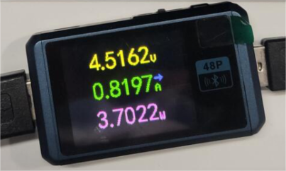
Question:What is the (max) power consumption?
Question: After the flash-on and flash-off parameters are set, does it need to be powered off and restarted to take effect?
No, after sending a flash-on and flash-off command and running it, you can directly send a second command without restarting
Support
Monday-Friday (9:30-6:30) Saturday (9:30-5:30)
Email: services01@spotpear.com
[Tutorial Navigation]
- Overview
- Development Protocol V3
- Resources
- FAQ
- Question:Can you supply the environmental specifications for this device?
- Question:What is the (max) power consumption?
- Question: After the flash-on and flash-off parameters are set, does it need to be powered off and restarted to take effect?
- Support