


- sales/support
Google Chat:---
- sales
+86-0755-88291180
- sales01
sales@spotpear.com
- sales02
dragon_manager@163.com
- support
tech-support@spotpear.com
- CEO-Complaints
zhoujie@spotpear.com
- Only Tech-Support
WhatsApp:13246739196
- Purchase/Shipping/Refund
WhatsApp:13424403025
- HOME
- >
- ARTICLES
- >
- Common Moudle
- >
- UART Module
D500-LiDAR-Kit Guide
Resource
Document
SDK
Software
3D Model
Overview
Introduction
STL-19P is mainly composed of a laser ranging core, a wireless transmission unit, a wireless communication unit, an angle measuring unit, a motor driving unit, and a mechanical case. The STL-19P ranging core adopts DTOF technology to measure 5000 times each second. When it works, STL-19P emits the infrared laser forward, and the laser is reflected in the single photon receiving unit after encountering the target object. Thus, we get both the time of laser emitting and receiving, the gap between them is the time of flight. We can calculate the distance by dividing the flight time by the speed of light. After receiving distance data, STL-19P will combine them with angel value from the angle measurement unit to comprise the points cloud data, then transmit the points cloud data to an external interface via wireless communication. Meanwhile, the external interface provides PWM to allow the motor driving unit to drive the motor. After the external control unit gets the rotational speed, it will reach to specified speed through PID algorithm closed-loop control to ensure STL-19P works stably.
Feature
- Based on DTOF (Time of Flight) laser ranging technology
- Support UART communication
- Measuring radius 12m
- 60K Lux anti-glare interference
- 5000Hz measurement frequency
- 360° scanning range
- Laser Safety Meets FDA Class 1 Standards
- Compact appearance
- 10000+ hours of service life
Parameter
| Typical measuring range | 0.03~12m |
| Sampling frequency | 5000 Hz |
| Scanning frequency | 10 Hz |
| Angular resolution | ≤0.72° |
| Mechanical size | 38.59*38.59*33.50mm |
| Communication interface | UART @ 230400bps |
| Supply voltage | 5V |
| Working current | 290mA |
| Power consumption | 1.45W |
| Operating temperature range | -10℃~40℃ |
| Scanning range | 360° |
| Ranging accuracy | 10mm (300mm<measurement distance<=500mm) 20mm (500mm<measurement distance<=2000mm) 30mm (2000mm<measurement distance<=12000mm) |
Application
- Education and Research
- Robot obstacle avoidance
- Measurement and Inspection
- Smart Gesture Control
- 2D Gesture Recognition
- Autonomous navigation
- Map reconstruction
- Navigation and positioning
How to use
Communication
STL-19P adopts a ZH1.5T-4P1.5mm standard socket to connect with the external system for power supply, rotation control, and data output. The specific interface definition and parameter requirements are as follows:
| No | Function | Type | Description | Minimum | Typical values | Maximum |
|---|---|---|---|---|---|---|
| 1 | Tx | Output | Lidar Data Output | 0V | 3.3V | 3.5V |
| 2 | PWM | Input | Motor Control Signal | 0V | - | 3.6V |
| 3 | GND | Power | Power negative | - | 0V | - |
| 4 | P5V | Power | Power positive | 4.5V | 5V | 5.5V |
STL-19P has a continuously variable motor driver inside, which supports internal speed control and external speed control. When the PWM pin is not connected or connected to high resistance, the Lidar will use internal speed control, and the default speed is 10Hz. When the PWM pin connects to a square wave signal, the Lidar will use external speed control, and the start, stop and speed of the motor can be controlled by the duty cycle of the PWM signal. Because of the individual differences of each motor driver, the actual speed may be different when the duty cycle is set as a typical value. If need to accurately control the motor speed, you should do closed-loop control via the rotation speed information from the receiving data. The data communication of STL-19P uses a standard asynchronous serial port(UART) in one way, and the transmission parameters are shown below:
| Baud Rate | Data Bits | Stop Bits | Parity | Flow Control |
|---|---|---|---|---|
| 230400 | 8 Bits | 1 | No | No |
STL-19P adopts one-way communication. After working stably, it begins to send measuring data without any instruction.
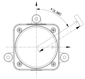
Coordinate System Definition
STL-19P uses the left-handed coordinate system, the front side of the sensor is defined as the x-axis (namely the zero direction), the rotation center is the coordinate origin, and the rotation angle increases along the clockwise direction. Please refer to the below picture:
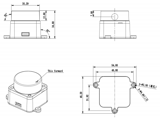
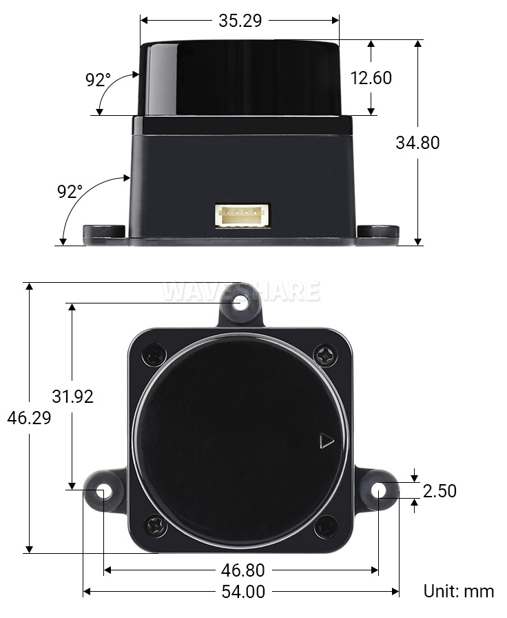
Optical Windows and Mechanical Dimensions
The laser emission and reception of the STL-19P measurement unit will require an optical window that should be structurally sheltered. Any shielding on the outside of the window will affect the measurement performance of the STL-19P to some extent. The following figure shows the dimensions of the optical window (unit: mm):

The shaded part in the above picture is the optical window. Please do not cover it. The remaining installation dimensions (Unit: mm) are shown below:
Tolerance: ±0.2mm
Software
- Ld_desktop_V2.3.12.zip
- CP210x_Universal_Windows_Driver.zip
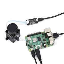
- The Lidar is connected to the adapter board, and then connected to the computer through USB.
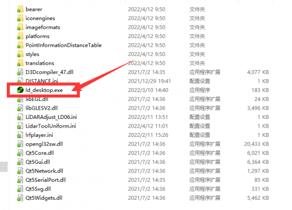
- Download ld_desktop_V2.3.12.zip and unzip it.
- Run ld_desktop.exe in the compressed package.
- Select Device LDS19.
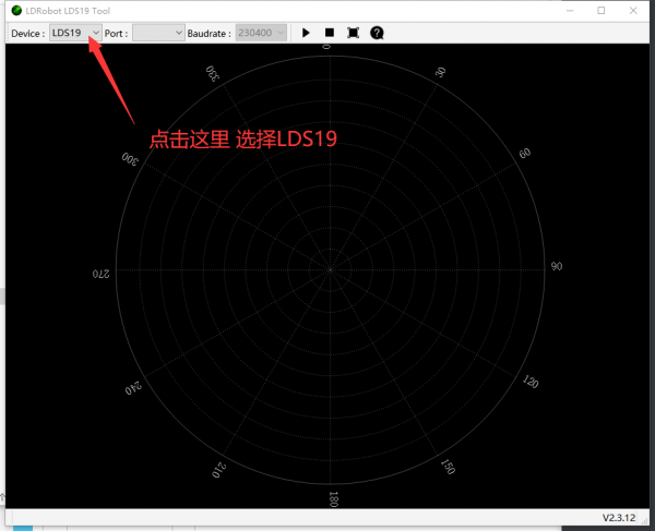
- Select the COM port. If there is no COM port on the Lidar (CP2102 on the adapter board), you need to download CP210x_Universal_Windows_Driver.zip and install the driver.
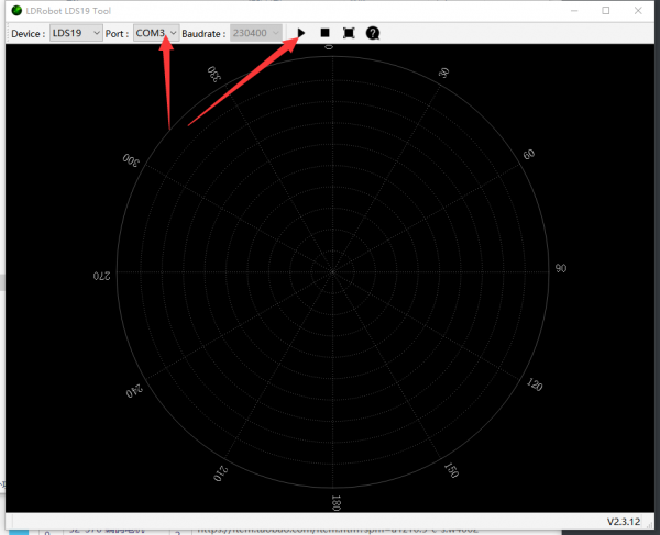
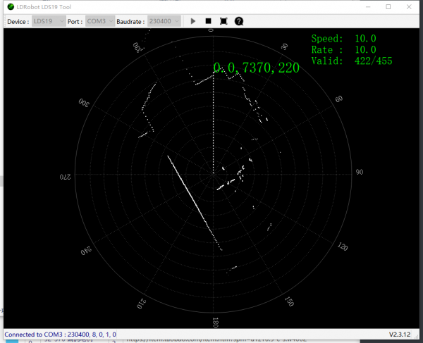
- After clicking the triangle icon above, you can see the scanning results of the radar on the computer.
Dimensions