


- sales/support
Google Chat:---
- sales
+86-0755-88291180
- sales01
sales@spotpear.com
- sales02
dragon_manager@163.com
- support
tech-support@spotpear.com
- CEO-Complaints
zhoujie@spotpear.com
- Only Tech-Support
WhatsApp:13246739196
- Purchase/Shipping/Refund
WhatsApp:13424403025
- HOME
- >
- ARTICLES
- >
- Common Moudle
- >
- Power
Modbus-POE-ETH-Relay-C User Guide
Overview
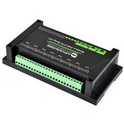
- This product is an industrial grade dual Ethernet ports controlled 8-ch relay module with 8-channel digital inputs, adopts Modbus RTU/Modbus TCP protocols, supports PoE power supply, also comes with ABS housing design. This relay module is very easy to use. Due to its fast communication, stability, reliability, and safety, it is an ideal choice for industrial control equipments and/or applications with high communication requirements.
Electrical Safety Precautions
- This product should be operated and used by professional electricians or technical personnel. During use, please ensure electrical safety and take protective measures such as anti-leakage and insulation.
- Before installing, maintaining, or replacing relay equipment, make sure to turn off the power and unplug the device.
- Do not attempt to dismantle relay equipment to avoid damaging the device or risking electric shock.
- Please properly install and place the relay equipment. Avoid using it in damp, overly hot, or flammable environments to prevent safety accidents due to improper installation or use.
Specifications
| Power Supply | PoE network port, DC 5.5*2.1 power connector or terminal block (7~36V) |
|---|---|
| Communication Interface | PoE network port, supports IEEE 802.3af standard |
| Relay Channels | 8 Channels |
| Contact Form | 1NO 1NC |
| Contact Load | ≤10A 250V AC 或 ≤10A 30V DC |
| Digital Input | 8DI, 5~36V, passive/active input (NPN or PNP), built-in bi-directional optocoupler |
| Modbus Protocol | Modbus RTU protocol or Modbus TCP protocol |
Indicator Light Description
| Indicator | Status description |
|---|---|
| RUN indicator | Ethernet port running indicator, outputs a square wave with a period of 2 seconds when the Ethernet port working normally. |
| STA indicator | MCU indicator, blinking when the MCU working normally. |
| TXD indicator | Send indicator, lights up when sending data. |
| RXD indicator | Receive indicator, lights up when receiving data. |
| Green light on left Ethernet port | Lights up when port 1 connected to the Ethernet |
| Green light on right Ethernet port | Lights up when port 2 connected to the Ethernet |
| Yellow light on left Ethernet port | The yellow indicator will be on when TCP connection is established, which can be used to determine whether the module has established a communication link with the host software |
| Yellow light on right Ethernet port | Data activity indicator, when data is transmitted through the Ethernet port, the yellow indicator changes its state, which can be used to determine if there is data transmission |
Primary Functions
Supports reading digital input by sending Modbus RTU protocol commands via Ethernet, and can control relay output based on input.
Wiring Description
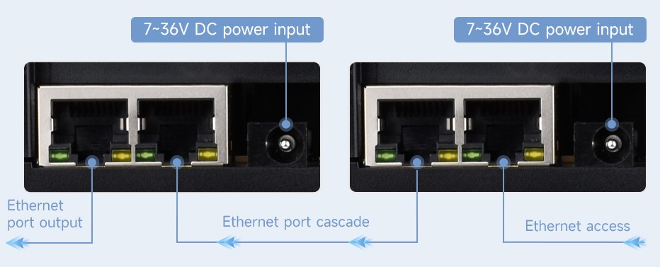
- Connect the module to the LAN via a network cable, and supply power through 7~36V power port or the POE. Both Ethernet ports are functionally the same and can be used for network port communication and cascading.
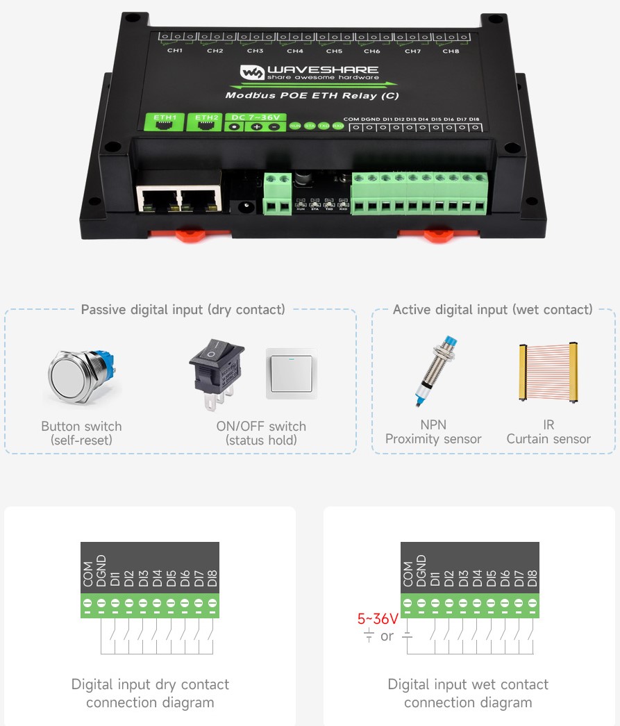
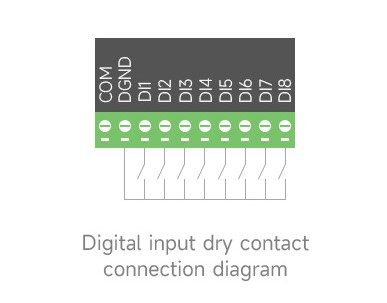
DI1-DI8 are the 8-channel signal input terminals, and DGND is the signal terminal ground. COM is the common terminal for the input signal, it can be NC (Not Connected), connected to the positive or negative poles of the power supply, directly powered from the power supply or connected to an independent power supply.
- COM not connected: dry contact passive input
- COM connected to the positive pole of power supply: low active, NPN wet contact active input, voltage: 5V-30V DC
- COM connected to the negative pole of power supply: high active, PNP wet contact active input
PNP Digital Input 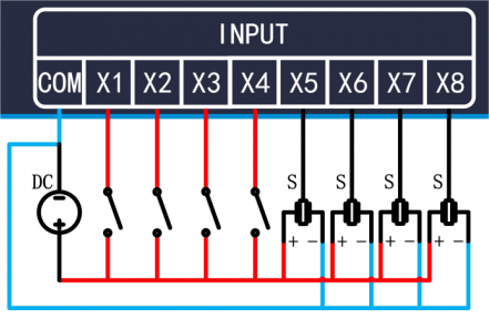
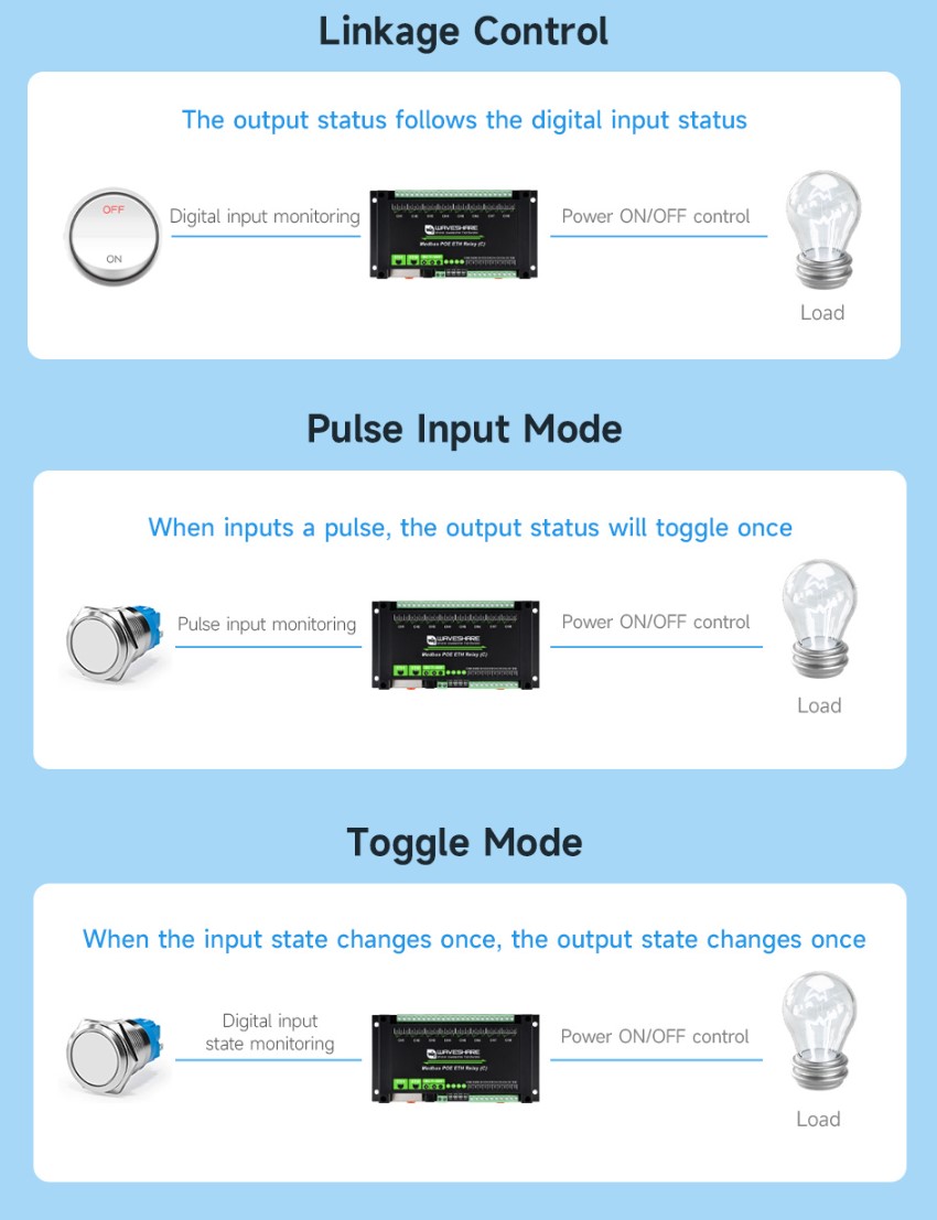
Operation Modes Introduction
The relay supports multiple control modes, and each channel supports independent setting of control modes</ p>
- Note: The output of the linkage mode is only controlled by the input and does not respond to the command. Except for the Linkage Control, other modes support controlling relays via commands.

Module Parameter Configuration
The module needs to set the module parameters before communication, such as IP address, serial port format, Modbus protocol, etc. There are two modes of setting parameters: Vircom software configuration and web configuration.
Vircom software configuration allows for setting more parameters, but requires software installation. Web configuration does not require installation, but you need to know the IP address first, and the configuration parameters are few. It is recommended to use Virom for configuration.
Note:
1. The configuration can be done in any way, and it is recommended to use Virom software for first test.
2. It is recommended to modify only the IP address for the first configuration, other parameters are not recommended to be modified. The serial port parameters must be the default parameters; modifying the serial port parameters will result in no communication.
3. The module supports both Modbus RTU and Modbus TCP protocols. In the Advanced Settings -> Transfer Protocol, you can choose "None", which means the Modbus RTU protocol. It is not recommended to modify during the first configuration.
4. The selected Modbus TCP protocol must be configured using the Virom software and set to a non-storage Modbus gateway, otherwise the communication will not be normal.
Virom Software Mode Configuration
General Settings
Connect the module to the hardware and connect it to the network. Run the VirCom software (the computer on which Vircom is installed must be on the same LAN as the module).
The operation is as follows:
- ① Click
Device - ② Click
Auto Search - ③ The software searches for and identifies devices connected to the LAN
- ④ Select the device, and then click
Edit Deviceor double-click the searched device directly - ⑤ Set the working parameters of the device:
- Click the "Local IP" button to identify the IP address of the computer, modify the "IP address" to a static assigned address, and note that the static IP address entered is not used by other devices, and it needs to be on the same LAN as the computer.
- The working mode is TCP server. The serial port setting is 115200 by default and cannot be modified.
- The "Transfer Protocol" in "Advanced Settings" defaults to "None", which means using the Modbus RTU protocol; if you select "Modbus TCP protocol", then use the Modbus TCP protocol for communication.
- Click the "Local IP" button to identify the IP address of the computer, modify the "IP address" to a static assigned address, and note that the static IP address entered is not used by other devices, and it needs to be on the same LAN as the computer.
- ⑥ Once the settings are complete, click
Modify Setting - ⑦ Click
Restart Dev, wait for the module to restart, and the new settings will take effect.
Note: It is recommended to modify only the IP address for the first configuration, and do not modify other parameters.
See the figure below for details: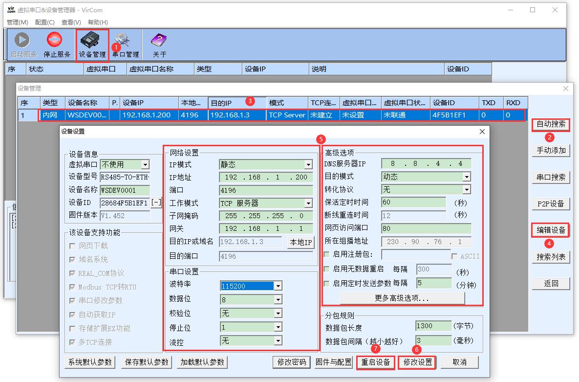
Protocol Setting
Note: It is recommended to use the default Modbus RTU protocol for the first configuration and no modifications are needed.
Although the module transmits data through the network port, it supports two Modbus protocols: Modbus RTU and Modbus TCP. By default, data is transparently transmitted, i.e. using the Modbus RTU protocol.
The "Transfer Protocol" in the "Advanced Settings" can be set to Modbus TCP protocol. In this case, the Modbus RTU protocol of the main controller will be converted to the Modbus TCP protocol and transmitted through the network port.
In this case, the device port automatically changes to 502. Users can connect their Modbus TCP tool to the IP of the serial port server on port 502.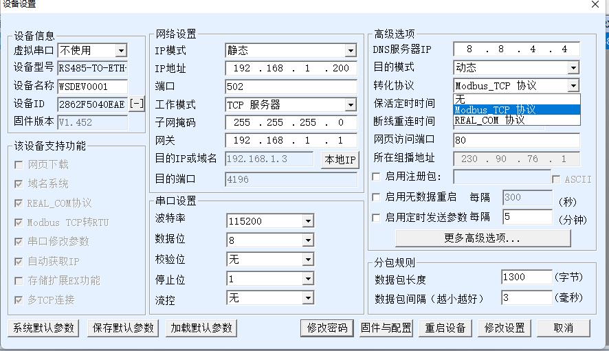
- If set to Modbus TCP protocol, it also needs to be set to a non-storage Modbus network port. Click on "More Advanced Settings..." and select the Modbus Gateway Type as a non-storage Modbus gateway.
Note: The default Modbus gateway type is storage type, which will automatically send query commands several times, which may cause the controller chip not to respond, and the query commands will not be affected. Therefore, you need to set it as Multi-host non-storage type. 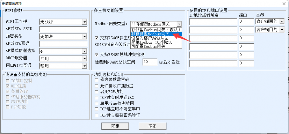
Virtual Serial Port Setting
The module transmits data through a network port (TCP/UDP protocol). In order to enable users to communicate even with developed serial port software, a virtual serial port needs to be added. If not needed, this part can be skipped.
First, install the virtual serial driver Virtual serial port driver, and run Vircom and the user program on the same computer.
Vircom virtualizes a COM port that corresponds to the serial port server. When the user program opens the COM communication, it can send data to the user's serial port device through the Vircom serial port server. The following steps demonstrate this operation:
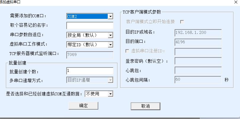
Click on "Serial Port & Device Management" on the Vircom main interface, then click "Add" and select to add COM2 (Among them, COM2 is the newly emerging COM port on the computer).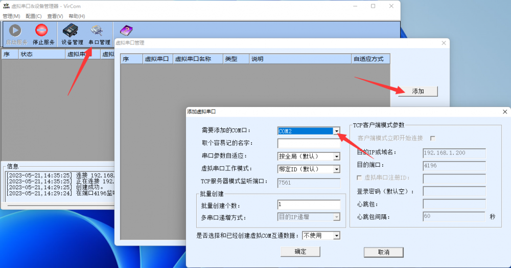
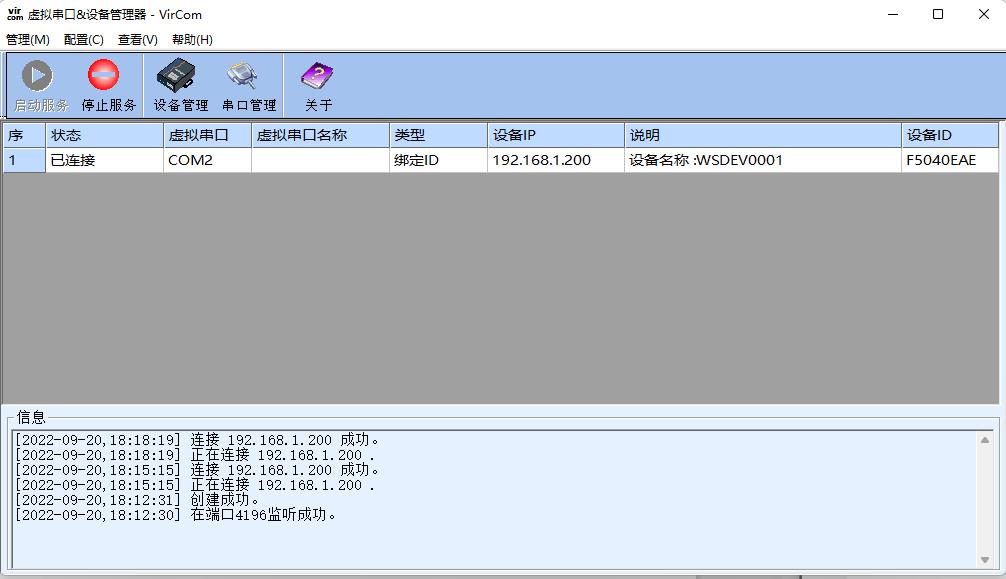
- Then enter the device management and double-click the device that needs to be bound to COM2. As shown in the diagram, select COM2 from the Virtual Serial Port list in the top left corner. Then click on "Modify Setting" and then click on "Restart Device".
- Return to the main interface of Vircom. It can be seen that COM2 has been connected to the device whose IP is 192.168.1.200. In this case, the virtual serial port COM2 can be used instead of the network port for communication.
WEB Configuration
Using Vircom, you can search for and configure device parameters in different network segments. For Web configuration, you must first ensure that the computer and the serial server are in the same IP segment, and you need to know the IP address of the serial server in advance.
But Web configuration can be done on any computer without Vircom. (Different products have different web interfaces, which can be switched between Chinese and English)
1. Enter the IP address of the serial server in the browser, such as http://192.168.1.200 to open the following web page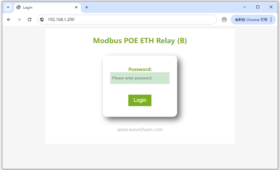
2. Enter password in "Password": There is no login password set by default in the factory, you can enter a password at will, and click the Login button to log in. After setting the password to log in, the settings at "Modify Web Login Key" will take effect: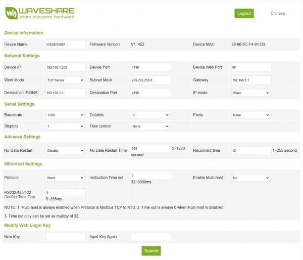
3. The serial server parameters can be modified on the web page that appears.
4. After modifying the parameters, click the "Submit" button.
Attention: The system has added webpage settings function by default when it leaves the factory. If the configuration interface page file is overwritten and the webpage cannot be opened, the webpage file needs to be downloaded again.
Please refer to RS485 TO ETH (B) Manual
Example Demonstration
The demo shows how the following two software operate.
SSCOM serial port debugging assistant is more convenient to operate, free of installation, and more convenient for complete display and analysis of instructions, but the disadvantage is that the data is not intuitive.
Modbus Poll software is directly operated on the register, and the data display is more convenient to observe, but the disadvantage is that the instruction is not displayed completely, so you need to be familiar with the Modbus register operation.
You can test using any method. It is recommended to use the SSCOM serial port debugging assistant software for the first test.
SSCOM Serial Port Debugging Assistant
- Open the serial debugging assistant window, select TCPClient for the port number, modify the remote IP and port number according to the above Vircom settings, select ModbusCRC16 if you need to add the check. Click the "Connect" button to connect to the TCP server, the green light of the network port will light up after successful connection.
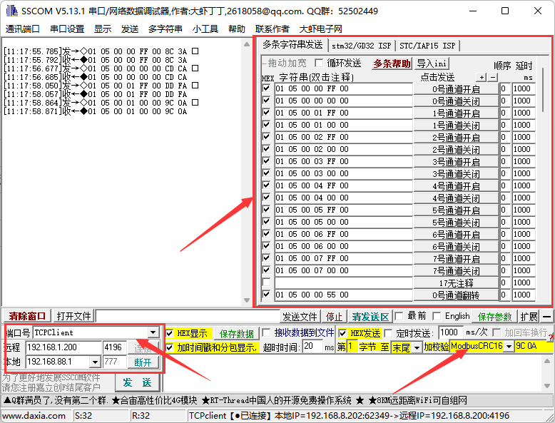
Click Multi-Char to open the Send Multi-Char window, the default display is the Modbus RTU command, and there is no CRC check, select ModbusCRC16 if you need to add the check. Click on the function to send the corresponding command.
Note: The module defaults to normal mode at the factory, the relay can be directly commanded and controlled. If there is a command to return normally, but the relay does not act, the module may have been changed to other control mode, you can query it by reading the relay control mode command.
- The default configuration is Modbus RTU command. If set to Modbus TCP command, the command needs to be changed. *Click on the Import ini button in the Send Multi-Char column, and select the Modbus tcp.ini file to import.
If the error "A component named HEX0 already exists" is displayed, close the software and reopen it, then re-import the file.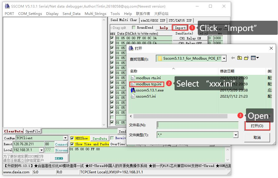
- After successful import, the following is displayed, click on the function to send the corresponding command.
Note: Modbus tcp does not require CRC checksum, select None for checksum.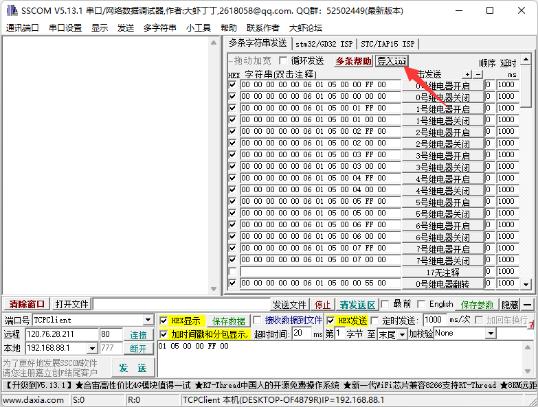
- For detailed Modubs commands, please see the development protocol.
Modbus Poll Software
- The serial port software is not convenient to observe the data, you can choose Modbus Poll software to read the data. Download and install the Modbus Poll software.
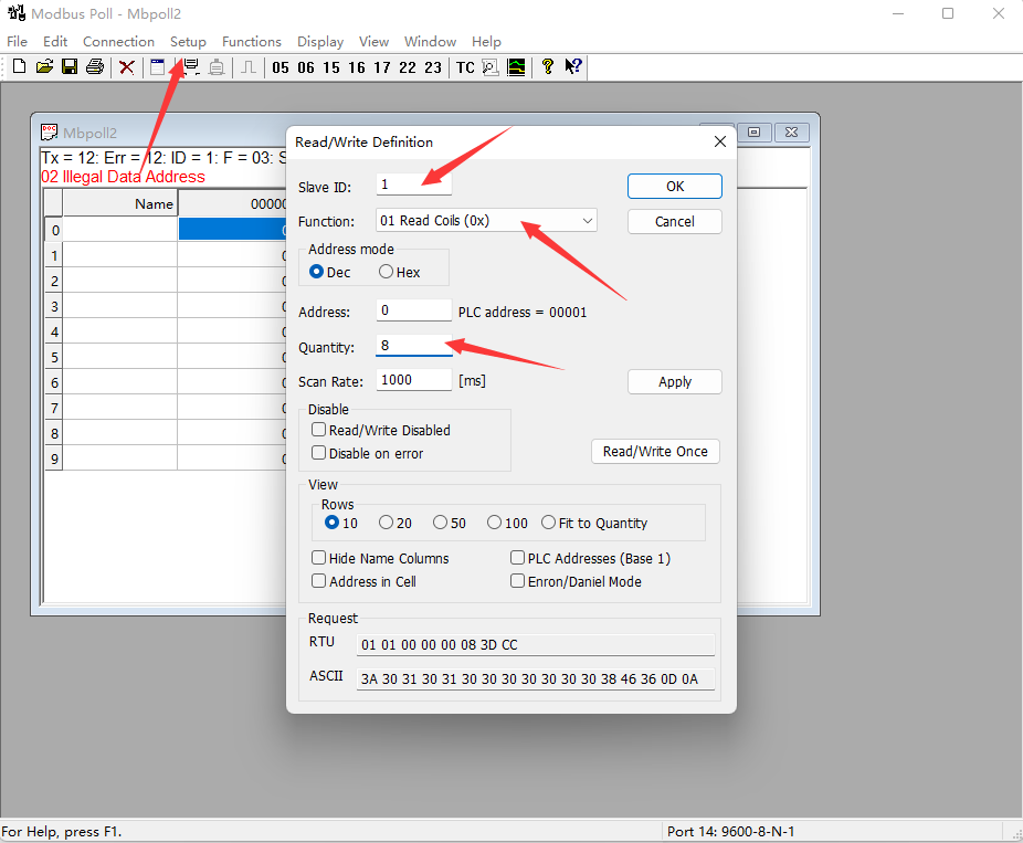
- Open the software, select Setup->Read/Write Definition, select the actual device address for Slave ID, select 01 Read Coils function code for Function, and change Quantity to 8 channels. Click OK to confirm.
- Select Connection ->Connect..., select the connection method for Connection.
If configured as Modbus RTU command, select Modbus RTU/ASCII Over TCP/IP, select the Mode as RTU. If configured as Modbus TCP command, select Modbus TCP/IP.
Enter the correct IP address and port number. Click OK to connect.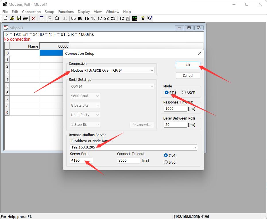
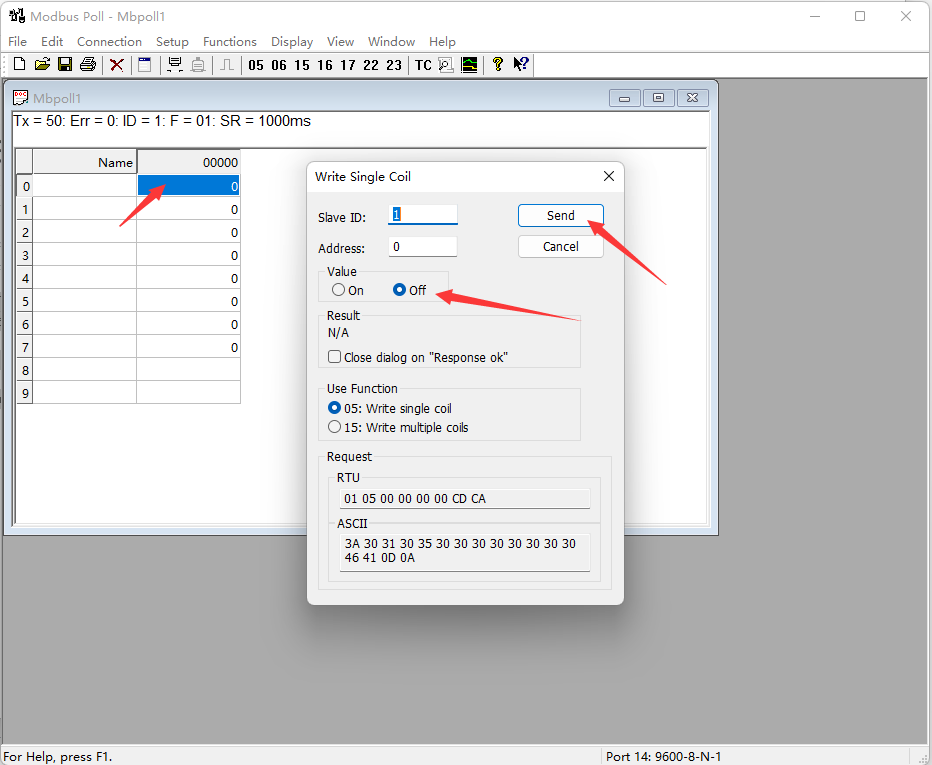
- After the connection is normal, you can check the current relay status. Select the corresponding channel, then double-click the status value to pop up the send page. Choose On or Off, then Click Send to control the relay opening and closing.
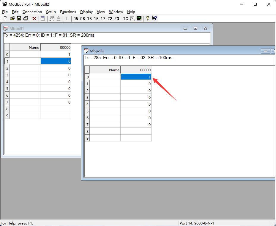
- Choose File->New to create a new window, select Setup->Read/Write Definition, choose the actual device address for Slave ID, select 02 for Function, set Address to 0, set Quantity to 8 channels, and change the Scan Rate to 100ms. Click OK to confirm.

- The new window 2 can display the current input status, change the input interface level, and the corresponding values will also change.
Demo
Raspberry Pi
Connect the Raspberry Pi and the ModBus POE ETH Relay module to the same LAN.
Open the Raspberry Pi terminal and run the program by entering the following command.
After the demo normally runs, each channel can be opened and closed sequentially, and finally the current input status is displayed.
sudo apt-get install unzip
wget https://files.waveshare.com/wiki/Modbus%20POE%20ETH%20Relay/Modbus_POE_ETH_Relay_B_Code.zip
unzip Modbus_POE_ETH_Relay_B_Code.zip
cd Modbus_POE_ETH_Relay_B_Code

#modbus rtu protocol
vi modbus_rtu.py  #Change the IP address and port number according to the actual situation
sudo python3 modbus_rtu.py

#modbus tcp protocol
vi modbus_tcp.py  #Change the IP address and port number according to the actual situation
sudo python3 modbus_tcp.py
Note: To run this demo, you need to modify the demo file to change the IP address and port number to the actual IP address and port number of the ModBus POE ETH Relay.
Development Protocol V2
Function Code Introduction
| Function Code | Description | |
|---|---|---|
| 01 | Read coil status | Read relay status |
| 02 | Read discrete input status | Read input status |
| 03 | Read holding register | Read the address and version |
| 05 | Write single coil | Write single relay |
| 06 | Write single register | Set the baud rate and address |
| 0F | Write multiple coils | Write relay status |
| 10 | Set multiple registers | Set multiple registers |
Register Address Introduction
| Address (HEX) | Address storage content | Register value | Permission | Modbus Function Code |
|---|---|---|---|---|
| 0x0000 …… 0x0007 | Channel 1~8 relay address | 0xFF00: relay on 0x0000: relay off 0x5500: relay toggle | Read/Write | 0x01, 0x05, 0x0F |
| 0x00FF | Control all relays | 0xFF00: all relays on 0x0000: all relays off 0x5500: all relays toggle | Write | 0x05 |
| 0x0100 …… 0x0107 | Channel 1~8 relay toggle address | 0xFF00: relay toggle 0x0000: relay unchanged | Write | 0x05, 0x0F |
| 0x01FF | Control all relays toggle | 0xFF00: all relays toggle 0x0000: all relays unchanged | Write | 0x05 |
| 0x0200 …… 0x0207 | Channel 1~8 relay flash on | Interval time: data*100ms Value: 0x0007, Interval time: 7*100MS = 700MS | Write | 0x05 |
| 0x0400 …… 0x0407 | Channel 1~8 relay flash off | Interval time: data*100ms Value: 0x0007, Interval time: 7*100MS = 700MS | Write | 0x05 |
| 1x0000 …… 1x0007 | Channel 1~8 input address | Indicates channel 1~8 input channel status | Read | 0x02 |
| 4x1000 …… 4x1007 | Channel 1~8 relay control mode | 0x0000~0x0003 four control modes | Read/Write | 0x03, 0x06, 0x10 |
| 4x4000 | Device Address | Directly store Modbus address Device address: 0x0001 | Read | 0x03 |
| 4x8000 | Software Version | Converting to decimal and then shifting the decimal point two places to the left will represent the software version 0x0064 = 100 = V1.00 | Read | 0x03 |
Modbus RTU Command Introduction
Control Single Relay
Send code: 01 05 00 00 FF 00 8C 3A
| Field | Description | Note |
|---|---|---|
| 01 | Device Address | Fixed 0x01 |
| 05 | 05 Command | Relay control |
| 00 00 | Address | The register addresses of the relays to be controlled, 0x0000-0x0007 |
| FF 00 | Command | 0xFF00: relay on; 0x0000: relay off; 0x5500: relay toggle |
| 8C 3A | CRC16 | The CRC16 checksum of the first 6 bytes of data |
Return code: 01 05 00 00 FF 00 8C 3A
| Field | Description | Note |
|---|---|---|
| 01 | Device Address | Fixed 0x01 |
| 05 | 05 Command | Relay control |
| 00 00 | Address | The register address of the relay to be controlled, 0x0000-0x0007 |
| FF 00 | Command | 0xFF00: relay on; 0x0000: relay off; 0x5500: relay toggle |
| 8C 3A | CRC16 | The CRC16 checksum of the first 6 bytes of data |
For example: [Address 1 device]:
Relay 0 on: 01 05 00 00 FF 00 8C 3A
Relay 0 off: 01 05 00 00 00 00 CD CA
Relay 1 on: 01 05 00 01 FF 00 DD FA
Relay 1 off: 01 05 00 01 00 00 9C 0A
Relay 2 on: 01 05 00 02 FF 00 2D FA
Relay 2 off: 01 05 00 02 00 00 6C 0A
Relay 3 on: 01 05 00 03 FF 00 7C 3A
Relay 3 off: 01 05 00 03 00 00 3D CA
Relay 0 toggle: 01 05 00 00 55 00 F2 9A
Relay 1 toggle: 01 05 00 01 55 00 A3 5A
Relay 2 toggle: 01 05 00 02 55 00 53 5A
Relay 3 toggle: 01 05 00 03 55 00 02 9A
Control All Relays
Send code: 01 05 00 FF FF 00 BC 0A
| Field | Description | Note |
|---|---|---|
| 01 | Device Address | Fixed 0x01 |
| 05 | 05 Command | Relay control |
| 00 FF | Address | Fixed 0x00FF |
| FF 00 | Command | 0xFF00: relay on; 0x0000: relay off; 0x5500: relay toggle |
| BC 0A | CRC16 | The CRC16 checksum of the first 6 bytes of data |
Return code: 01 05 00 FF FF 00 BC 0A
| Field | Description | Note |
|---|---|---|
| 01 | Device Address | Fixed 0x01 |
| 05 | 05 Command | Relay control |
| 00 FF | Address | Fixed 0x00FF |
| FF 00 | Command | 0xFF00: relay on; 0x0000: relay off; 0x5500: relay toggle |
| BC 0A | CRC16 | The CRC16 checksum of the first 6 bytes of data |
For example: [Address 1 device]:
All relays on: 01 05 00 FF FF 00 BC 0A
All relays off: 01 05 00 FF 00 00 FD FA
All relays toggle: 01 05 00 FF 55 00 C2 AA
Read Relay Status
Send code: 01 01 00 00 00 08 3D CC
| Field | Description | Note |
|---|---|---|
| 01 | Device Address | Fixed 0x01 |
| 01 | 01 Command | Query relay status |
| 00 00 | Start Address | Relay start address, 0x0000-0x0007 |
| 00 08 | Relay Number | Cannot exceed the maximum number of relays |
| 3D CC | CRC16 | The CRC16 checksum of the first 6 bytes of data |
Receive code: 01 01 01 00 51 88
| Field | Description | Note |
|---|---|---|
| 01 | Device Address | Fixed 0x01 |
| 01 | 01 Command | Query relay status |
| 01 | Byte Number | The number of all bytes of the returned status information |
| 00 | Query status | Received relay status Bit0: the first relay status; Bit1: the second relay status; And so on, with the idle high bit being zero |
| 51 88 | CRC16 | The CRC16 checksum of the first 6 bytes of data |
For example: [Address 1 device]:
Send: 01 01 00 00 00 08 3D CC       //Query all relays
Receive: 01 01 01 00 51 88    //all relays off
Send: 01 01 00 02 00 01 5C CA       //Query relays 2
Receive: 01 01 01 01 90 48    //Relay 1 on
Send: 01 01 00 01 00 03 2D CB       //Query relays 1, 2, 3 status
Receive: 01 01 01 05 91 8B               //Relays 1 and 3 are on, relay 2 is off
Write Relay Status
Send code: 01 0F 00 00 00 08 01 FF BE D5
| Field | Description | Note |
|---|---|---|
| 01 | Device Address | Fixed 0x01 |
| 0F | 0F Command | Write relay status |
| 00 00 | Relay Start Address | The register address of the relay to be controlled, 0x0000 - 0x0007 |
| 00 08 | Relay Number | The number of relays to be operated, which must not exceed the maximum number of relays |
| 01 | Byte Number | The byte number of the status |
| FF | Relay Status | Bit0: the first relay status; Bit1: the second relay status; And so on, with the idle high bit being zero |
| BE D5 | CRC16 | The CRC16 checksum of the first 6 bytes of data |
Receive code: 01 0F 00 00 00 08 54 0D
| Field | Description | Note |
|---|---|---|
| 01 | Device Address | Fixed 0x01 |
| 0F | 0F Command | Control all registers |
| 00 00 | Address | Relay start address |
| 00 08 | Relay Number | The number of relays to be written |
| 54 0D | CRC16 | The CRC16 checksum of the first 6 bytes of data |
For example: [Address 1 device]:
All relays on: 01 0F 00 00 00 08 01 FF BE D5
All relays off: 01 0F 00 00 00 08 01 00 FE 95
0-1 on; 3-7 off: 01 0F 00 00 00 08 01 03 BE 94
Relays 1, 2, and 3 on: 01 0F 00 01 00 03 01 07 F3 55
Relay Flash ON/OFF Command
Send code: 01 05 02 00 00 07 8D B0
| Field | Description | Note |
|---|---|---|
| 01 | Device Address | Fixed 0x01 |
| 05 | 05 Command | Single control command |
| 02 | Command | 02: flash on, 04: flash off |
| 00 | Relay Address | The address of the relay to be controlled, 0x00~0x07 |
| 00 07 | Interval Time | The interval time: data*100ms Value: 0x0007, Interval time: 7*100MS = 700MS The maximum setting for the flash-on flash-off time is 0x7FFF |
| 8D B0 | CRC16 | The CRC16 checksum of the first 6 bytes of data |
Receive code: 01 05 02 00 00 07 8D B0
| Field | Description | Note |
|---|---|---|
| 01 | Device Address | Fixed 0x01 |
| 05 | 05 Command | Single control command |
| 02 | Command | 02: flash on, 04: flash off |
| 00 | Relay Address | The address of the relay to be controlled, 0x00~0x07 |
| 00 07 | Interval Time | The interval time: data*100ms Value: 0x0007, Interval time: 7*100MS = 700MS The maximum setting for the flash-on flash-off time is 0x7FFF |
| 8D B0 | CRC16 | The CRC16 checksum of the first 6 bytes of data |
For example: [Address 1 device]:
Relay 0 flash on: 01 05 02 00 00 07 8D B0  //700MS = 7*100MS = 700MS
Relay 1 flash on: 01 05 02 01 00 08 9C 74  //800MS
Relay 0 flash off: 01 05 04 00 00 05 0C F9  //500MS
Relay 1 flash off: 01 05 04 01 00 06 1D 38  //600MS
Read Input Status
Send code: 01 02 00 00 00 08 79 CC
| Field | Description | Note |
|---|---|---|
| 01 | Device Address | Fixed 0x01 |
| 02 | 02 Command | Read input status |
| 00 00 | Input Start Address | Input start address, 0x0000-0x0007 |
| 00 08 | Register Number | The number of the input channels to be read, which must not exceed the maximum number of the input channels |
| 79 CC | CRC16 | The CRC16 checksum of the first 6 bytes of data |
Receive code: 01 02 01 00 A1 88
| Field | Description | Note |
|---|---|---|
| 01 | Device Address | Fixed 0x01 |
| 02 | 02 Command | Read input status |
| 01 | Byte Number | The number of all bytes of the returned status information |
| 00 | Query status | Received input channel status Bit0: the first channel status; Bit1: the second channel status; And so on, with the idle high bit being zero |
| A1 88 | CRC16 | The CRC16 checksum of the first 6 bytes of data |
For example: [Address 1 device]:
Send: 01 02 00 00 00 08 79 CC    //Query all input channels
Receive: 01 01 01 00 51 88    //Inputs are all untriggered
Send: 01 02 00 00 00 08 79 CC    //Query all input channels
Receive: 01 02 01 41 61 B8    //Channels 1 and 7 input is triggered, and the rest of channels are not triggered
Send: 01 02 00 01 00 03 69 CB       //Query input channels 2, 3, and 4
Receive: 01 02 01 03 E1 89    //Channels 2 and 3 input is triggered, and channel 4 is not triggered
Read Relay Control Mode
Send code: 01 03 10 00 00 08 40 CC
| Field | Description | Note |
|---|---|---|
| 01 | Device Address | Fixed 0x01 |
| 03 | 03 Command | Read Holding Register |
| 10 00 | Register Start Address | 0x1000 - 0x1007 corresponds to 1~8 input channels |
| 00 08 | Register Number | Read register number, up to 8 channels |
| 40 CC | CRC16 | The CRC16 checksum of the first 6 bytes of data |
Receive code: 01 03 10 00 00 00 00 00 00 00 00 00 00 00 00 00 00 00 00 E4 59
| Field | Description | Note |
|---|---|---|
| 01 | Device Address | Fixed 0x01 |
| 03 | 03 Command | Read Holding Register |
| 10 | Byte Number | The number of all bytes of the returned status information |
| 00 00 …… 00 00 | Control Mode | Indicates relay 1 - 8 control mode, 0x0000~0x0003 indicate four control modes 0x0000: Normal mode, the relay is directly controlled by commands;0x0001: Linkage mode, relay status is the same as the corresponding input channel status;0x0002: Toggle mode, the corresponding relay toggles once when the input channel inputs a pulse;0x0003: Jump Mode, the corresponding relay status toggles once when the input channel level jumps once |
| E4 59 | CRC16 | The CRC16 checksum of the first 6 bytes of data |
For example: [Address 1 device]:
Read relay 1-8 control mode: 01 03 10 00 00 08 40 CC
Read relay 1 control mode: 01 03 10 00 00 01 80 CA
Read relay 2 control mode: 01 03 10 01 00 01 D1 0A
Read relay 3-5 control mode: 01 03 10 02 00 03 A0 CB
Set Single Relay Control Mode
Send code: 01 06 10 00 00 01 4C CA
| Field | Description | Note |
|---|---|---|
| 01 | Device Address | Fixed 0x01 |
| 06 | 06 Command | Write single register |
| 10 00 | Register Start Address | 0x1000 - 0x1007 correspond to relay control modes for channels 1~8 |
| 00 01 | Control Mode | Indicates relay 1 - 8 control mode, 0x0000~0x0003 indicate four control modes 0x0000: Normal mode, the relay is directly controlled by commands;0x0001: Linkage mode, relay status is the same as the corresponding input channel status;0x0002: Toggle mode, the corresponding relay toggles once when the input channel inputs a pulse;0x0003: Jump Mode, the corresponding relay status toggles once when the input channel level jumps once |
| 4C CA | CRC16 | The CRC16 checksum of the first 6 bytes of data |
Return code: 01 06 10 00 00 01 4C CA
| Field | Description | Note |
|---|---|---|
| 01 | Device Address | Fixed 0x01 |
| 06 | 06 Command | Write single register |
| 10 00 | Register Start Address | 0x1000 - 0x1007 correspond to relay control modes for channels 1~8 |
| 00 01 | Control Mode | Relay control modes, 0x0000~0x0003 indicate four control modes |
| 4C CA | CRC16 | The CRC16 checksum of the first 6 bytes of data |
For example: [Address 1 device]:
Set relay 1 as Linkage mode: 01 06 10 00 00 01 4C CA
Set relay 2 as toggle mode: 01 06 10 01 00 02 5D 0B
Set Multiple Relay Control Mode
Send code: 01 10 10 00 00 08 10 00 01 00 01 00 01 00 01 00 01 00 01 00 01 00 01 7C B1
| Field | Description | Note |
|---|---|---|
| 01 | Device Address | Fixed 0x01 |
| 10 | 10 Command | Write multiple registers |
| 10 00 | Register Start Address | 0x1000 - 0x1007 correspond to relay control modes for channels 1~8 |
| 00 08 | Register Number | Set register number, up to 8 channels |
| 10 | Byte Number | Set the number of bytes to be output |
| 00 01 …… 00 01 | Control Mode | Indicates relay 1 - 8 control mode, 0x0000~0x0003 indicate four control modes 0x0000: Normal mode, the relay is directly controlled by commands;0x0001: Linkage mode, relay status is the same as the corresponding input channel status;0x0002: Toggle mode, the corresponding relay status toggles once when the input channel inputs a pulse;0x0003: Jump Mode, the corresponding relay state toggles once when the input state of the input channel changes once |
| 7C B1 | CRC16 | The CRC16 checksum of the first 6 bytes of data |
Return code: 01 10 10 00 00 08 C5 0F
| Field | Description | Note |
|---|---|---|
| 01 | Device Address | Fixed 0x01 |
| 10 | 10 Command | Write multiple registers |
| 10 00 | Register Start Address | 0x1000 - 0x1007 correspond to relay control modes for channels 1~8 |
| 00 08 | Register Number | Set register number, up to 8 channels |
| C5 0F | CRC16 | The CRC16 checksum of the first 6 bytes of data |
For example: [Address 1 device]:
Set channel 1-8 relay as Normal mode: 01 10 10 00 00 08 10 00 00 00 00 00 00 00 00 00 00 00 00 00 00 00 00 0B 5C
Set channel 1-8 relay as Linkage mode: 01 10 10 00 00 08 10 00 01 00 01 00 01 00 01 00 01 00 01 00 01 00 01 7C B1
Set channel 3-5 relay as Toggle mode: 01 10 10 02 00 03 06 00 02 00 02 00 02 4A 4B
Read Software Version Command
Send code: 01 03 80 00 00 01 AD CA
| Field | Description | Note |
|---|---|---|
| 01 | Device Address | Fixed 0x01 |
| 03 | 03 Command | Read Holding Register |
| 80 00 | Command register | 0x8000: read software version |
| 00 01 | Byte Number | Fixed 0x0001 |
| AD CA | CRC16 | The CRC16 checksum of the first 6 bytes of data |
Receive code: 01 03 02 00 64 B9 AF
| Field | Description | Note |
|---|---|---|
| 01 | Device Address | Fixed 0x01 |
| 03 | 03 Command | Read Holding Register |
| 02 | Byte Number | The number of bytes returned |
| 00 64 | Software Version | Converting to decimal and then shifting the decimal point two places to the left will represent the software version 0x0064 = 100 = V1.00 |
| B9 AF | CRC16 | The CRC16 checksum of the first 6 bytes of data |
For example:
Send: 01 03 80 00 00 01 AD CA
Receive: 01 03 02 00 C8 B9 D2       //0x00C8 = 200 =V2.00
Exception Function Code
When the received command is incorrect or the device is abnormal, an exception response will be returned in the following format:
Receive: 01 85 03 02 91
| Field | Description | Note |
|---|---|---|
| 01 | Device Address | 0x00 indicates the broadcast address, 0x01-0xFF indicates the device address |
| 85 | Exception Function Code | Exception function code = Request function code + 0x80 |
| 03 | Byte Number | Exception Code |
| 02 91 | CRC16 | The CRC16 checksum of the first 6 bytes of data |
An exception code is a single-byte value that indicates the type of error. Several commonly used exception codes defined by the Modbus protocol:
| Exception Code | Name | Description |
|---|---|---|
| 0x01 | Illegal Function | The requested function code is not supported |
| 0x02 | Illegal Data Address | The requested data address is incorrect |
| 0x03 | Illegal Data Value | The requested data value or operation cannot be executed |
| 0x04 | Server Failure | Server equipment failure |
| 0x05 | Response | The request has been received and is being processed |
| 0x06 | Device Busy | The device is currently busy and cannot perform the requested operation |
Modbus TCP Command Introduction
Here is a brief introduction to Modbus TCP and Modbus RTU protocol conversion using the above commands to open the first relay as an example.
- Modbus RTU command: 01 05 00 00 FF 00 8C 3A
| Field | Description | Note |
|---|---|---|
| 01 | Device Address | Fixed 0x01 |
| 05 | 05 Command | Relay control |
| 00 00 | Address | The register address of the relay to be controlled, 0x00, that is, the first relay |
| FF 00 | Command | 0xFF00: Relay on |
| 8C 3A | CRC16 | The CRC16 checksum of the first 6 bytes of data |
- Modbus TCP command: 00 00 00 00 00 06 01 05 00 00 FF 00
| Field | Description | Note |
|---|---|---|
| 00 00 | Message Label | Both be 0x00 |
| 00 00 | modbus Label | Must both be 0, which means this is Modbus communication |
| 00 06 | Byte Length | Indicates the number of all bytes that follow, followed by 6 bytes |
| 01 | Device Address | Fixed 0x01 |
| 05 | 05 Command | Relay control |
| 00 00 | Address | The register address of the relay to be controlled, 0x00, that is, the first relay |
| FF 00 | Command | 0xFF00: Relay on |
By comparing the commands above, we can observe that to convert a Modbus RTU command to Modbus TCP protocol, the CRC check is removed, and the command is prefixed with five 0x00 bytes followed by a byte representing the length.
For example, if the server's Ethernet port receives a Modbus TCP command of 00 00 00 00 00 06 01 05 00 00 FF 00 (to turn on the first relay), the host controller will receive the Modbus RTU command of 01 05 00 00 FF 00 8C 3A.
Advanced Applications
- Relay control through Alibaba Cloud MQTT
- Relay control through Waveshare Cloud
- Relay control through HTTP GET/POST
Resources
Demo
Software
- VirCom_en: English version of the configuration software
- Virtual-serial-port : Virtual serial port driver
- Sscom5.13.1 for Modbus POE ETH Relay B: Sscom software
- Modbus Poll software
- SecureCRT software
Related Resources
FAQ
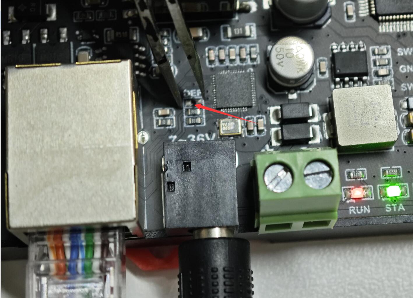
Question: I forgot the parameters set by Vircom for the network port, how can I restore the factory settings?
- To restore the setting parameters of the network port, you need to disassemble the shell, use tweezers to short the pad under the DEF silk screen for more than 5s, and the module will be reset to the IP of 192.168.1.254.
Operating temperature: -15℃ ~ 70℃
Support
Monday-Friday (9:30-6:30) Saturday (9:30-5:30)
Email: services01@spotpear.com
[Tutorial Navigation]
- Overview
- Electrical Safety Precautions
- Specifications
- Primary Functions
- Wiring Description
- Operation Modes Introduction
- Module Parameter Configuration
- Example Demonstration
- Demo
- Development Protocol V2
- Function Code Introduction
- Register Address Introduction
- Modbus RTU Command Introduction
- Control Single Relay
- Control All Relays
- Read Relay Status
- Write Relay Status
- Relay Flash ON/OFF Command
- Read Input Status
- Read Relay Control Mode
- Set Single Relay Control Mode
- Set Multiple Relay Control Mode
- Read Software Version Command
- Exception Function Code
- Modbus TCP Command Introduction
- Advanced Applications
- Resources
- FAQ
- Question: I forgot the parameters set by Vircom for the network port, how can I restore the factory settings?
- Question: What is the operating temperature range of the relay?
- Support