


- sales/support
Google Chat:---
- sales
+86-0755-88291180
- sales01
sales@spotpear.com
- sales02
dragon_manager@163.com
- support
tech-support@spotpear.com
- CEO-Complaints
zhoujie@spotpear.com
- Only Tech-Support
WhatsApp:13246739196
- Purchase/Shipping/Refund
WhatsApp:13424403025
- HOME
- >
- ARTICLES
- >
- Common Moudle
- >
- LCD
0.71inch-Dual-Eye-LCD-Moudle User Guide
Introduction
Introduction
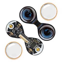
The 0.71inch binocular LCD module features two 0.71inch round IPS screens with 160 x 160 pixels, equipped with a GC9D01 driver chip, and utilizes SPI interface communication. It is suitable for integration into controllers such as ESP32, Raspberry Pi Pico, Arduino, etc., and can be used in creative applications like simulated electronic eyes or wearable devices.
Specifications
| Operating voltage | Communication interface | Display panel | Control chip |
|---|---|---|---|
| 3.3V/5V | 4-wire SPI | IPS | GC9D01 |
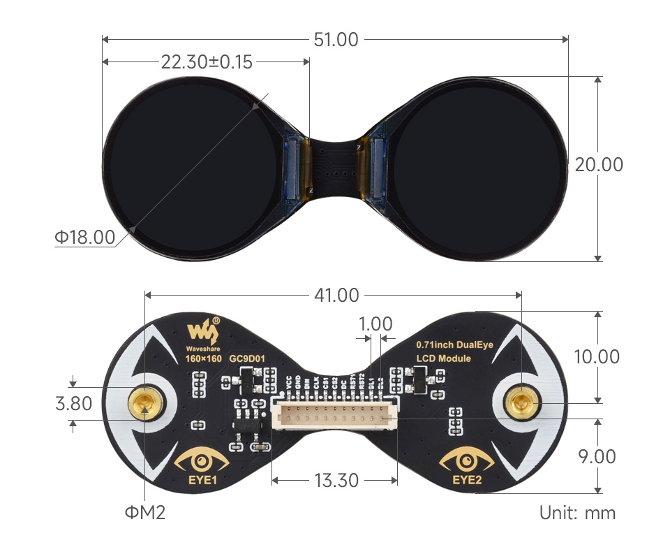
| Resolution | Display size | Pixel pitch | Dimensions |
| 160 × 160 pixels | 18 × 18 (mm) | 37.5 × 112.5 (μm) | 20.00 × 51.00 (mm) |
Pinout Definition
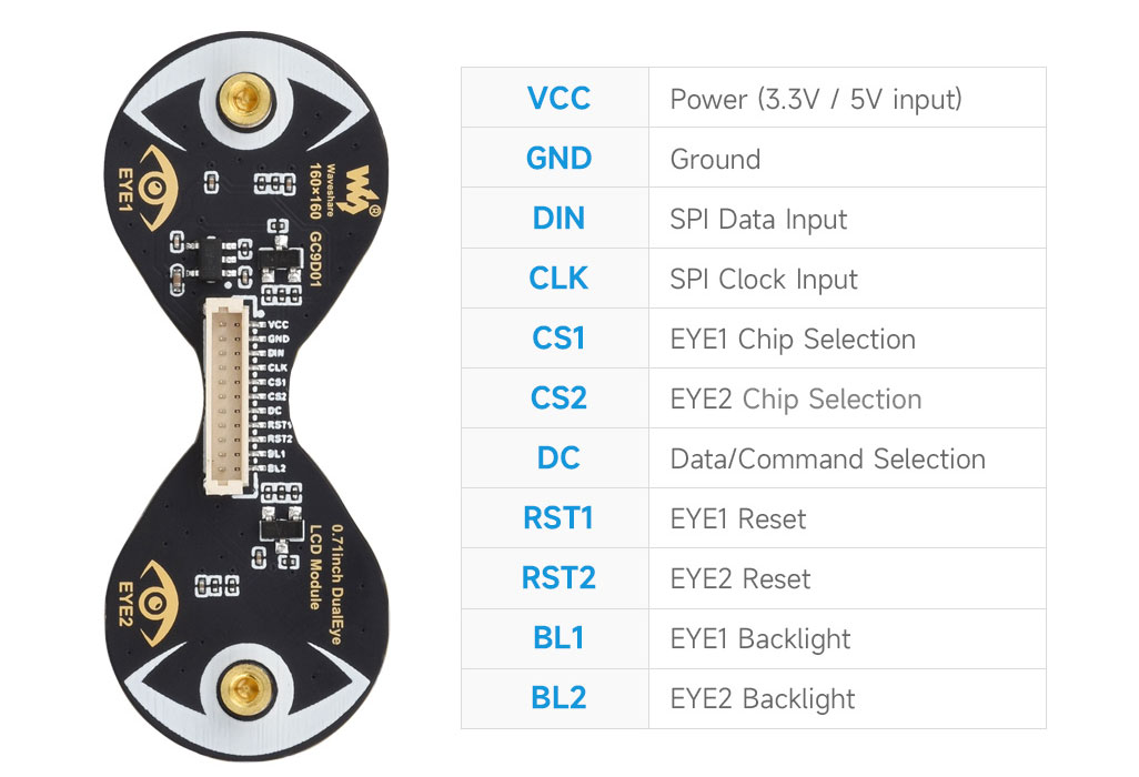
Operating Principle
LCD and its Controller
This LCD uses the built-in GC9D01 driver, with a resolution of 160×160. It has an internal GRAM and supports 12/16/18-bit data bus MCU interfaces, i.e., RGB444, RGB565, RGB666 three color formats, which are common RGB formats.
For most LCD controllers, the communication interface can be configured, including 8080 parallel, 3-wire SPI, 4-wire SPI, etc. This LCD uses a 4-wire SPI interface, which saves GPIO pins and increases communication speed.
Communication Protocol
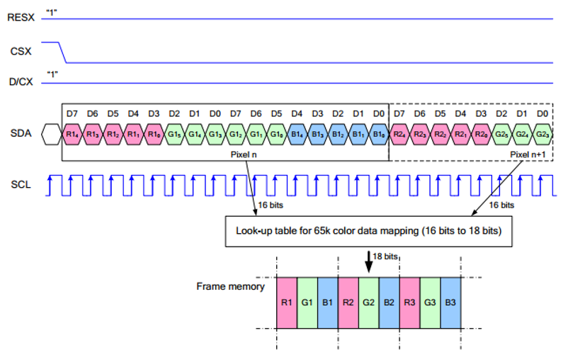
Note: The difference from the traditional SPI protocol is that the data line sent from the slave to the host is hidden because it only needs to be displayed.
RESX is the reset pin, it is pulled low when the module is powered on, usually set to 1;
CSX is the slave chip select pin, and the chip is enabled only when CS is low.
D/CX is the data/command control pin of the chip, when DC = 0 a command is written; when DC = 1, data is written
SDA is the data transmitted data, that is, RGB data;
SCL is the SPI communication clock pin.
For SPI communication, the data transmission has timing sequences involving clock phase (CPHA) and clock polarity (CPOL):
CPHA determines whether data is captured on the first or second clock transition edge. When CPHA = 0, data is captured on the first clock transition edge;
CPOL determines the idle level of the clock, CPOL = 0 means low.
From the diagram, it can be seen that when SCLK falls on the first edge, data transmission starts. One clock cycle transmits 8 bits, using SPI0, bitwise transmission, high bit first, and low bit last.
Dimensions
User Guide
Working with ESP32S3和ESP32C3
Hardware Connection
- 11PIN cable connector
| LCD Pin | ESP32C3 |
| VCC | 3V3 |
| GND | GND |
| DIN | GPIO4 |
| CLK | GPIO7 |
| CS1 | GPIO6 |
| CS2 | GPIO2 |
| DC | GPIO9 |
| RST1 | GPIO8 |
| RST2 | GPIO5 |
| BL1 | GPIO1 |
| BL2 | GPIO3 |
Environment Setup
Download and Install Arduino IDE
- Click to visit the Arduino official website, select the corresponding system and system bit to download
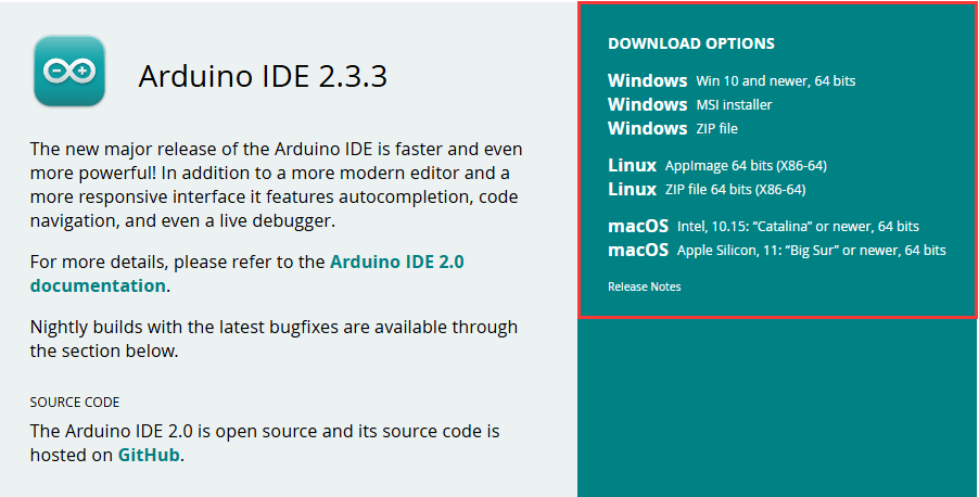
- Run the installer and install all by default
Install ESP32 development board
- To use ESP32 boards in Arduino IDE, first install the ESP32 Development Board
It is recommended to download and install ESP32_Arduino offline package (2.0.12 version recommended), and refer to Arduino board manager tutorial for the installation tutorial
Install Libraries
- The necessary library files for this product are located in the Demo folder:
0.71inch-LCD-Module-Demo\ESP32-C3\libraries\, with library instructions detailed below
| Library Name | Description | Library Installation Requirement |
|---|---|---|
| TFT_eSPI | LCD driver library | "Install Offline" |
| LVGL | LVGL library | "Install Offline" |
- For library offline installation tutorial, please refer to Arduino library manager tutorial
Demo
- Download the Demo and unzip it
- Open the demo and flash the program.
| Demo | Description | Dependency Library |
|---|---|---|
| 1.Text_and_Number_Display | Text and nymber display | TFT_eSPI |
| 2.Shapes_on_Circular_Display | Drawing | TFT_eSPI |
| 3.Animated_Eye1 | Simulated eye style1 | TFT_eSPI |
| 4.Animated_Eye2 | Simulated eye style2 | TFT_eSPI |
| 5.Animated_Eye12 | Simulated eye styles1 and 2, displayed alternately | TFT_eSPI |
| 6.Image_Display | Display image | TFT_eSPI and LVGL |
| 7.Clock | Clock | TFT_eSPI and LVGL |
- Arduino project configuration:
01_Text_and_Number_Display
【Demo description】
- This demo cycles through two-digit numbers from 00 to 99 on the TFT display and shows a series of color transitions when the program starts. Suitable for learning ESP32 interaction with the TFT screen, it can display a two-digit number that increases in cycles, with color transitions and text display, to test stability and reliability
【Hardware connection】
- Connect the development board to the computer

【Code analysis】
- setup():
setupfunction executes once when the program starts, primarily responsible for initializing the TFT display and performing some initial settingstft.init();initializes the TFT display, preparing for subsequent display operations- Implementing color transition effects through a series of
tft.fillScreen()anddelay(), demonstrating the color filling capabilities of the TFT display, enhancing the visual appeal during program startup tft.fillScreen(0x04FF);sets a specific background color,tft.setTextColor(TFT_WHITE, 0x04FF);sets the text color, ensuring the text is clearly visible against the background
- loop():
loopfunction continuously loops during the running process of the program, realizing the core functionality of displaying numberstft.drawString("Hello, Waveshare!", 30, 40, 2);displays a welcome message, enhancing the user experience- Number formatting: Convert the integer
numberto a stringdisplayNumber, and add a leading zero when the number is a single digit, ensuring that single-digit numbers are displayed as two-digit numbers tft.drawString(displayNumber, 55, 80, 6);displays formatted numbers at a specific font size at a specific location on the displaynumber++realizes self-increment of numbers, and resets to 0 whennumberexceeds 99, ensuring that the number cycles between 00 and 99delay(1000)controls the speed at which the numbers are updated, allowing users to clearly see the changes in the numbers
【Demo flashing】
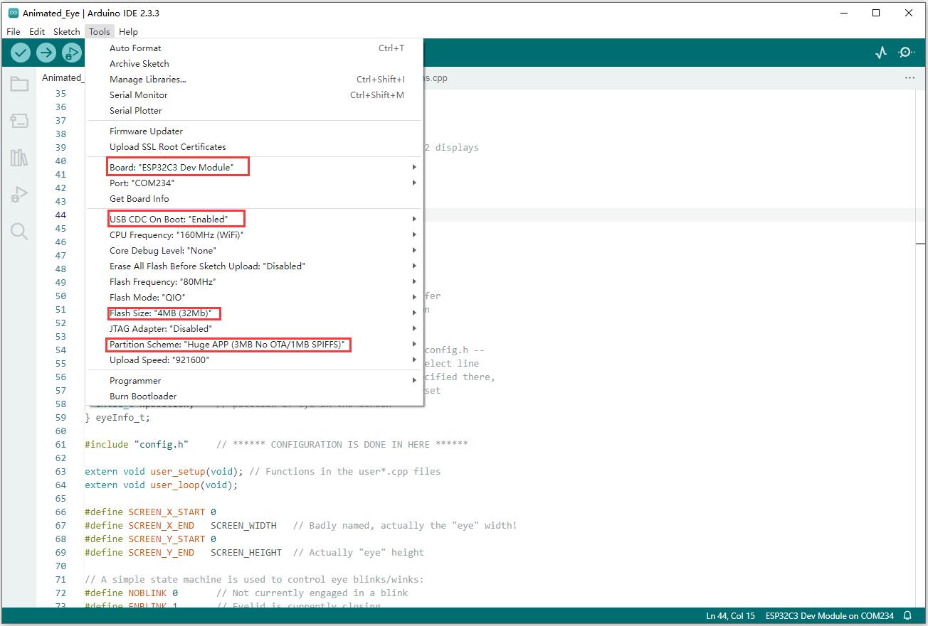
- Select the development board ESP32S3 Dev Module and port
- Set the parameters
- Flash the demo
【Result demonstration】

02_Shapes_on_Circular_Display
【Demo description】
- This demo achieves the effect of displaying random color squares, triangles, and circles in sequence on a circular display, demonstrating the graphic drawing capabilities and the flexibility of random color generation on a TFT display Applicable for learning ESP32 interaction with a circular display, sequentially drawing randomly colored squares, triangles, and circles centered on the screen, switching every 3 seconds, to test the stability of graphic drawing
【Hardware connection】
- Connect the development board to the computer
【Code analysis】
- drawSquare(): This function is used to draw a square filled with a random color
uint16_t squareColor = tft.color565(random(0, 255), random(0, 255), random(0, 255));generates a random RGB565 color, ensuring that the square is different in color each time it is drawn- The upper-left coordinates and dimensions of the square are determined by calculating the diagonal length of the square (equal to the diameter of the circle) and the center coordinates
tft.fillRect(squareTopLeftX, squareTopLeftY, squareSize, squareSize, squareColor);fills the square with a random color
- drawSquare(): This function draws an equilateral triangle filled with a random color
- Generates a random color
- Calculates the height and side length of an equilateral triangle based on the radius of the circle
- Calculates the coordinates of the three vertices of the triangle and store them in the
triangleXandtriangleYarrays tft.fillTriangle(triangleX[0], triangleY[0], triangleX[1], triangleY[1], triangleX[2], triangleY[2], triangleColor);fills the triangle with a random color
- drawCircleInCenter(): This function draws a circle filled with a random color, with the center located at the screen's center
- Generates a random color
tft.fillCircle(centerX, centerY, 30, circleColor);draws a circle with the screen center coordinates and a fixed radius, filling it with a random color
【Demo flashing】
- Select the development board ESP32S3 Dev Module and port
- Set the parameters
- Flash the demo
【Result demonstration】

03_Animated_Eye1
【Demo description】
- This demo utilizes the TFT_eSPI library to drive a TFT display and showcase an animated eye effect on different processors. It features configurable parameters and supports DMA to enhance performance, continuously updating the eye state in the main loop. Applicable for learning the TFT_eSPI library to display eye animations, it allows configuration of parameters, utilizing state machines to control blinking, and testing performance
【Hardware connection】
- Connect the development board to the computer
【Code analysis】
- updateEye(): Update the iris size of the eye according to different conditions (whether there is a light-sensitive pin or not) to achieve the response of the eye to light or automatic changes
- The function starts to determine how the iris size is updated based on whether
LIGHT_PINis defined - If a light-sensitive pin is defined:
- Reads the analog value of the light sensor pin with
int16_t v = analogRead(LIGHT_PIN); - Performs the necessary reversal operations according to the configuration such as
LIGHT_PIN_FLIP(#ifdef LIGHT_PIN_FLIPsection) - Limits the range of the read value (
if (v < LIGHT_MIN) v = LIGHT_MIN; else if (v > LIGHT_MAX) v = LIGHT_MAX;), ensuring that the light sensitivity value is within a reasonable range. - Performs a mapping of the light sensitivity value to the iris size range (
v = map(v, 0, (LIGHT_MAX - LIGHT_MIN), IRIS_MAX, IRIS_MIN);) - Apply a gamma curve to adjust the light sensitivity value depending on whether
LIGHT_CURVEis defined (#ifdef LIGHT_CURVEsection) - Finally, based on whether the
IRIS_SMOOTHis defined, choose the smoothing treatment (filtering method gradually adjusts the iris size) or directly set the iris size
- Reads the analog value of the light sensor pin with
- If a light-sensitive pin is not defined:
- Generate a random new iris size using
newIris = random(IRIS_MIN, IRIS_MAX); - Call the
split(oldIris, newIris, micros(), 10000000L, IRIS_MAX - IRIS_MIN);function to achieve a gradual change in iris size from the old value to the new value through a recursive method, and updateoldIriswith the new value
- Generate a random new iris size using
- The function starts to determine how the iris size is updated based on whether
【Demo flashing】
- Select the development board ESP32S3 Dev Module and port
- Set the parameters
- Flash the demo
【Result demonstration】

04_Animated_Eye2
【Demo description】
- The program achieves synchronized eye animation effects by controlling two TFT displays, making it suitable for visual demonstrations in scenarios such as robotic facial expressions and bionic eyes.
【Hardware connection】
- Connect the development board to the computer
【Code analysis】
- loop(): Continuously executes animations and updates the displayed content
- Use an inner loop to execute the
Demo_1function multiple times, where the number of times the loop runs is controlled by the variablei, with the loop running 7 times The image is displayed through the pushImage function, and the corresponding device is selected using the chip select signal before each display.
- Use an inner loop to execute the
【Demo flashing】
- Select the development board ESP32S3 Dev Module and port
- Set the parameters
- Flash the demo
【Result demonstration】

05_Animated_Eye12
【Demo description】
- Simulated eye styles1 and 2, displayed alternately
【Hardware connection】
- Connect the development board to the computer
【Code analysis】
- loop(): Continuously executes animations and updates the displayed content
- Use a loop to perform different animation operations:
- If
a == 1, then fill the screen with black first (tft.fillScreen(BLACK);), then call theDemo_1function, and finally delay 2 seconds withdelay(2000); - If
a == 2, then use an inner loop to execute theDemo_2function multiple times, where the number of times the loop runs is controlled by the variablei, with the loop running 7 times TheDemo_2function will sequentially display a series of images to achieve an animation effect. In this way, the two different animation sequences can be continuously executed in a loop during the operation of the program
- If
- Use a loop to perform different animation operations:
【Demo flashing】
- Select the development board ESP32S3 Dev Module and port
- Set the parameters
- Flash the demo
【Result demonstration】


06_Image_Display
【Demo description】
- This demo initializes the TFT display and LVGL library, creates an image object, and the main loop handles the timer task. It is applicable for learning how ESP32 interacts with LVGL and TFT screens, capable of displaying LVGL images after initialization, and testing for stability and reliability
【Hardware connection】
- Connect the development board to the computer
【Code analysis】
- lv_disp_flush(): Responsible for flashing the graphic data of LVGL to the TFT display
- First calculates the width
wand the heighthof the area to be refreshed, ensuring accurate determination of the data range - Then sets the write address window of the TFT display with
tft.setAddrWindow, specifying the correct position for data writing - Then uses
tft.pushColorsto push the color data to the display, this step determines the color and content of the displayed graphics - Finally, notifies LVGL that the refresh is complete so that LVGL can continue with subsequent graphics processing operations
- First calculates the width
- setup(): Sets serial port, LVGL, TFT display and display driver, creates and configures graphical objects
- Serial port initialization:
Serial.begin(115200)prepares the serial port communication for possible debugging - LVGL initialization:
lv_init()starts the core components of the LVGL library - If
LV_USE_LOGis not 0, register the serial print function for debugging:lv_log_register_print_cb(my_print) - TFT display Initialization:
tft.begin(): Initializes the TFT hardwaretft.setRotation(0): Sets the display orientation to landscape
- Display buffer initialization:
lv_disp_draw_buf_init(&draw_buf, buf, NULL, screenWidth * screenHeight / 10), preparing for storing graphic data - Display driver initialization and registration:
lv_disp_drv_init(&disp_drv)initializes the display driver structure- Sets driver parameters, such as resolution, refresh callback function, display buffer, etc., and registers the display driver
- Creates and sets up a graphical object:
- Declares image resources through
LV_IMG_DECLARE(A3), then creates an image object logo_img and sets its source to a declared image, and finally sets the position of the image object on the screen throughlv_obj_centerandlv_obj_align
- Declares image resources through
- Serial port initialization:
【Demo flashing】
- Select the development board ESP32S3 Dev Module and port
- Set the parameters
- Flash the demo
【Result demonstration】

07_Clock
【Demo description】
- This demo utilizes the TFT_eSPI library and the LVGL graphics library to initialize the TFT display, setting up a graphical interface framework to achieve display and interaction functions. It is applicable for learning how ESP32 interacts with LVGL and TFT screens, capable of displaying a graphical interface after initialization, and testing for stability and reliability
【Hardware connection】
- Connect the development board to the computer
【Code analysis】
- lv_disp_flush(): The display refresh callback function of LVGL, responsible for pushing LVGL's graphic data to the TFT display to ensure accurate update of the displayed content
- Calculates the width and height of the refresh area to accurately determine the data range to be pushed
- Sets the write address window for the TFT display, ensuring correct data write position
- Pushes color data to the display, the correct transmission of color data determines the color and content of the displayed graphics
- Notifies LVGL that the refresh is complete so that LVGL can continue with subsequent graphics processing operations
- setup(): Sets serial port, LVGL, TFT display, display driver, and initialization of the user interface
- Serial port initialization is used for possible debugging output
- LVGL initializes the core components of the boot library
- If
LV_USE_LOGis not 0, register the serial port print function to view the LVGL log information - TFT display initialization includes hardware connections and parameter settings, such as setting the rotation direction
- Initializes the display buffer and configures the display driver to ensure that LVGL interacts with the display correctly
- Calls
ui_initto initialize user interface elements - Outputs debugging information indicating initialization complete
【Demo flashing】
- Select the development board ESP32S3 Dev Module and port
- Set the parameters
- Flash the demo
【Result demonstration】

Working with Raspberry Pi Pico
Hardware Connection
- 11PIN cable connector
| LCD Pin | Raspberry Pi Pico |
| VCC | 3.3V |
| GND | GND |
| DIN | GPIO11 |
| CLK | GPIO10 |
| CS1 | GPIO9 |
| CS2 | GPIO13 |
| DC | GPIO8 |
| RST1 | GPIO12 |
| RST2 | GPIO15 |
| BL1 | GPIO20 |
| BL2 | GPIO21 |
Python Environment
Preparation
1. Install the (Thonny installation package)
2. Press the "BOOTSEL" key on the Raspberry Pi Pico, and release it after powering
3. A new disk will appear on your computer, extract the (Raspberry Pi Pico firmware) and copy the firmware (suffix uf2) to that disk (the disk will automatically disappear if the copy is successful)
4. Open Thonny, click on "Python x.x.x" at the bottom right, and select "Configure interpreter"
5. Select "Interpreter" in the pop-up window -> select "MicroPython (Raspberry Pi Pico)" as the interpreter -> select "Auto-detect port" as the port
6. Click on "Stop", and the Shell window will show "MicroPython v1.20.0-50-g786013d46 on 2023-05-04; Raspberry Pi Pico with RP2040 Type "help()" for more information. " It means the connection is successful
- The following is the procedure for steps 4 and 5:

- The successful connection is shown below:

Demo
- Download the Demo
- Unzip the demo and open Thonny
- Open the demo, the path is: 0.71inch-DualEye-LCD-Module-Demo\Raspberry Pi Pico\Eye.py

- Run the demo to achieve the blinking effect on the screen


Working with Arduino UNO
Hardware Connection
- 15PIN cable connector
- 11PIN cable connector
| LCD Pin | Arduino |
| VCC | 5V |
| GND | GND |
| DIN | D11 |
| CLK | D13 |
| CS1 | D6 |
| CS2 | D10 |
| DC | D7 |
| RST1 | D5 |
| RST2 | D8 |
| BL1 | NC |
| BL2 | NC |
Install Libraries
- When installing Arduino libraries, there are usually two ways to choose from: Install online and Install offline.
For most libraries, users can easily search and install them through the online library manager of the Arduino software. However, some open-source libraries or custom libraries are not synchronized to the Arduino Library Manager, so they cannot be acquired through online searches. In this case, users can only manually install these libraries offline. - For library installation tutorial, please refer to Arduino library manager tutorial
| Library Name | Description | Library Installation Requirement |
|---|---|---|
| TFT_eSPI | LCD driver library | "Install Offline" |
Demo
- Download the Demo and unzip it
- Enter the demo file 0.71inch-DualEye-LCD-Module-Demo/uno_r4, and double-click on main.ino to open the demo
- Select the device and the port, compile and flash the demo

- After successful flashing, it displays as following:
Flash Firmware Flashing and Erasing
- The current demo provides test firmware, which can be used to test whether the onboard device functions properly by directly flashing the test firmware
- bin file path:
..\xxx.bin
Resources
Documents
Demos
Firmware Flashing Tool
FAQ
Question: How to use SquareLine Studio to design interfaces?
- Please refer to SquareLine Studio tutorial
Question: How to distinguish between versions?
Modules equipped with this chip are the v2 version, while those without it are the v1 version.
Support
Monday-Friday (9:30-6:30) Saturday (9:30-5:30)
Email: services01@spotpear.com
[Tutorial Navigation]
- Introduction
- User Guide
- Working with ESP32S3和ESP32C3
- Working with Raspberry Pi Pico
- Working with Arduino UNO
- Flash Firmware Flashing and Erasing
- Resources
- FAQ
- Question: How to use SquareLine Studio to design interfaces?
- Question: How to distinguish between versions?
- Support