


- sales/support
Google Chat:---
- sales
+86-0755-88291180
- sales01
sales@spotpear.com
- sales02
dragon_manager@163.com
- support
tech-support@spotpear.com
- CEO-Complaints
zhoujie@spotpear.com
- Only Tech-Support
WhatsApp:13246739196
- Purchase/Shipping/Refund
WhatsApp:13424403025
- HOME
- >
- ARTICLES
- >
- Common Moudle
- >
- UART Module
RS485 TO ETH (C) User Guide
Overview
Introduction
This is an RS485 device data collector/IoT gateway specially designed for the industrial environment, which combines serial server, Modbus gateway, MQTT gateway, RS485 to JSON, and other functions. It has an RS485 interface and an Ethernet interface. It adopts the rail-type installation, which is compact and easy to install. It is very suitable for the collection of various RS485 devices and sensors in the industrial field, including the collection of the local network or the autonomous collection and uploading to the cloud server.
Parameters Comparision
| Model | RS485 TO ETH (B) | RS485 TO POE ETH (C) |
|---|---|---|
| Product Type | Serial server, Modbus Gateway, MQTT Gateway | |
| Basic Function | Bi-directional transparent data transmission between RS485 and Ethernet | |
| Communication Interface | RS485 × 1, Ethernet port × 1 | |
| Power Supply | Screw terminal DC 6~36V | Screw terminal DC 6~36V or PoE port |
| Isolation Protection | Without isolation | Power isolation, Signal isolation protection |
| Communication Interface | ||
| Ethernet | Common network port | PoE port, supports IEEE 802.3af standard |
| 10/100M self-adaptive RJ45 interface, 2 KV surge protection | ||
| Serial Port | RS485 | Isolated RS485 |
| UART Specifications | ||
| Baudrate | 300 ~ 115200 bps | |
| Parity Bit | none, odd, even, mark, space | |
| Data Bit | 5 ~ 9 bits | |
| Flow Control | N/A | |
| Software | ||
| Protocol | ETHERNET, IP, TCP, UDP, HTTP, ARP, ICMP, DHCP, DNS | |
| Configuration | Host, WEB browser, device management functions library | |
| Communication Method | TCP/IP direct communication, VCOM | |
| Operating Mode | TCP server, TCP client (coexisting with TCP server), UDP mode, UDP multicast | |
| Other | ||
| Operating Temperature | -40℃ ~ 85℃ | |
| Humidity Range | 5% ~ 95% relative humidity | |
| Dimensions | L × W × H: 87 × 36 × 59 mm | |
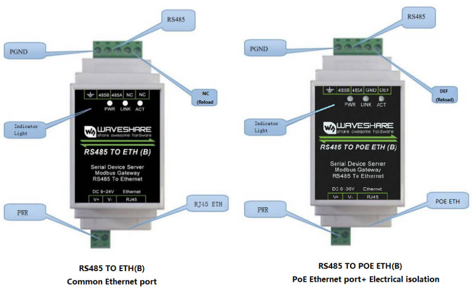
Hardware Description
| Indicator | Status Description |
| Power Light | Power indicator light |
| Link Light | (1) The Link light is green when the network cable is connected. (2) When a TCP connection is established (or in UDP mode), the Link is blue (actually with a faint green light). It can be used to determine whether the serial port server has established a communication link with the host computer software. |
| Active Light | (1) When the network port sends data to the serial port, the indicator light is green. The flashing time is 1 second longer than the actual communication time, making it easier to spot short data communications. (2) When the serial port sends data to the network port, the indicator light is blue and green at the same time. Since the blue is brighter, if you see the blue light, it indicates that the serial port is returning data to the network port. This can be used to determine if the device is responding to commands from the host computer; if there is no response, it suggests that the serial port baud rate is incorrect or the serial port is not properly connected. |
Software Features
- Supports TCP server, TCP client, UDP mode, and UDP multicast. When acting as a TCP client, it also supports TCP server-side functions. It supports 30 TCP connections as a TCP server and 7 destination IPs as a TCP client.
- The baud rate supports 300~115200bps, the data bit supports 5~9 bits, and the check digit can be no check, odd check, even check, mark, or space.
- Supports the function of sending MAC address when the device is connected, which is convenient for cloud management of the device.
- Provides a secondary development kit DLL development library for searching for and configuring devices on the computer side.
- Supports Web browser configuration, obtaining dynamic IP via DHCP, DNS protocol connected domain server address.
- Supports cloud remote search for devices, the configuration of device parameters, and device program upgrades.
- Supports remote viewing of the device's TCP connection status, and serial port data sending and receiving status through software. The virtual serial port supports the data monitoring function.
Advanced Software Functions
- Supports Modbus gateway function, support Modbus RTU to Modbus TCP. It can support storage-type Modbus, and can automatically collect device data and store it; it also supports a non-storage mode Modbus gateway.
- Supports multi-host function: In the query mode of one question and one answer, supports that the network port allows multiple computers to access the same serial device at the same time.
- Supports MQTT gateway function.
- Supports JSON to Modbus RTU and 645 device protocols, and supports uploading data in HTTP POST and HTTP GET formats.
- Supports NTP protocol to obtain network time, which is used for serial output, and the latter is used for protocol content upload.
- Supports custom heartbeat package and registration package function: It is convenient to communicate with the cloud and identify devices.
- Supports the function that password authentication is required to establish a connection through TCP to ensure connection security.
- Supports the function of data submission and delivery in HTTP mode, and the cloud can directly use the HTTP GET command to interact with the serial port data of the device.
Applications
- As an IoT gateway, serving as a communication bridge between devices and the cloud
- Electricity, smart meters, and energy consumption monitoring
- Remote monitoring and program download of various automation PLCs
- Various configuration software and equipment communication interfaces
- Access control security field equipment networking
Quick Test
Hardware Connection
- Here RS485 TO ETH (B) is taken as an example, and RS485 TO POE ETH (B) is connected in the same way.
Generally speaking, the serial server only needs to connect the power supply, serial port, and network cable. Among them, the power supply can use the field 2-wire power supply, which can be directly connected to the positive and negative terminals of the power supply. The serial port needs to be connected according to the user's serial port device. Connect 485 positive to 485A and 485 negative to 485B. You can connect a network port with a regular network cable to a computer directly or through a switch to connect to the network.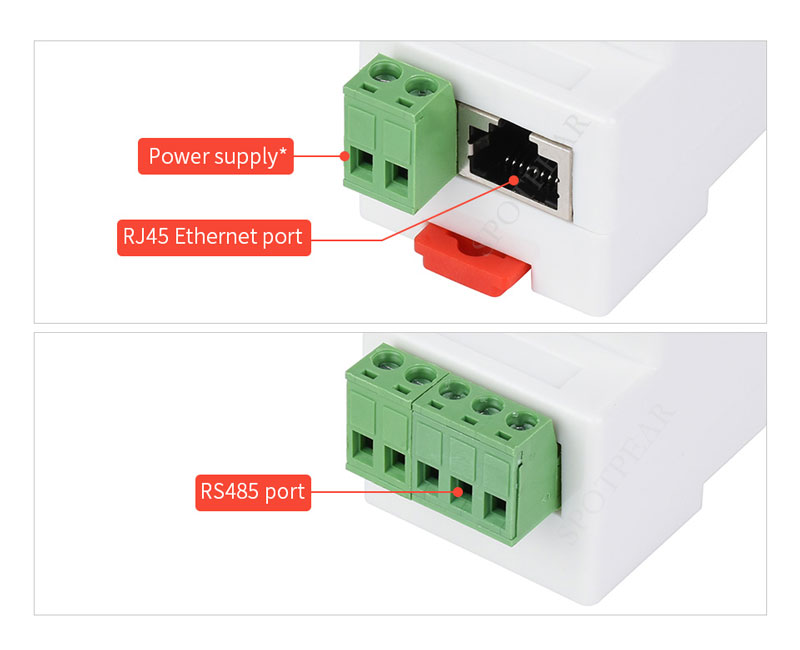
For the power supply range, please refer to the label of the corresponding version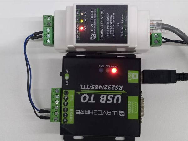
Software Installation
Vircom can be used to configure parameters such as device IP and create virtual serial ports. If you don't need the virtual serial port function, you can download the installation-free version of the configuration software only.
- VirCom_en : English version of the configuration software
- Virtual-serial-port : Virtual serial port driver
To install the driver, you need to unzip it, double-click the software to install. If the virtual serial port is not displayed in Vircom, restart it and check again.
Example Demonstration
TCP Communication Test
Software Preparation
Operation Steps
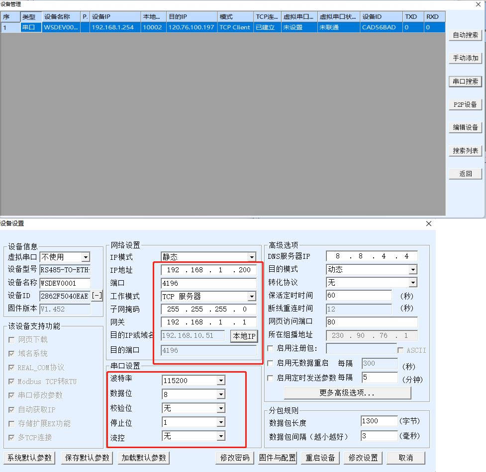
After Vircom is installed and the device hardware connection is finished, the software is run as shown in the figure, and then you can click "Device Management" as shown in the figure. With Vircom, it is very convenient to search for and configure device parameters in different network segments, as long as the device and the computer running Vircom are under the same switch.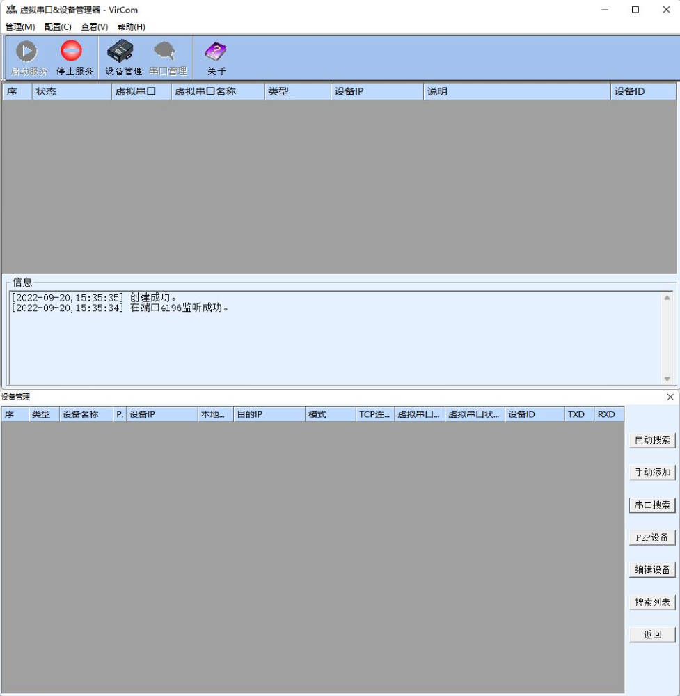
The following tests also require a USB TO RS485 device.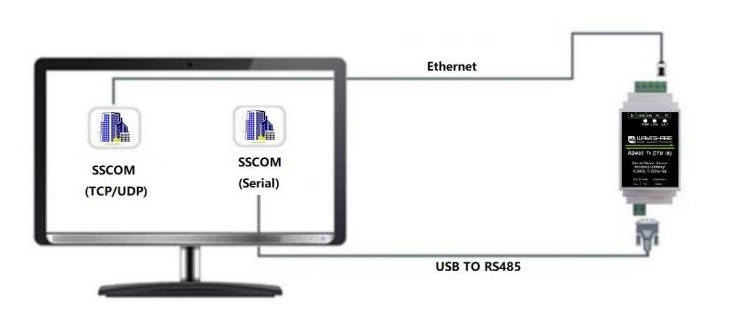
The serial port to network port and network port to serial port data transparent forwarding function of the serial port server. Assuming that the COM port (USB TO RS485) of the PC is now connected to the serial port of the serial port server, then open the serial port debugging assistant window and open the corresponding COM port, as shown below:
In addition, open another serial port debugging assistant window and use it as a TCP client mode, fill in the destination IP as the IP of the serial port server (currently 192.168.1.200), the destination port as 4196, and then click the "Open" button, as shown in the figure below:

In the serial debugging assistant SSCOM2 set as TCPClient, enter "TCPClient: Waveshare Test" and click Send, then the data will be transferred to the RS485 interface through the serial server's network port, and then sent to the USB TO RS485, and then displayed in the serial debugging assistant SSCOM1 out; conversely, enter "USB TO RS485: Waveshare Test" in SSCOM1, click send, you can also send to SSCOM2, and display it.
Virtual Serial Port Test
In order to allow users to communicate with the serial port server using their existing serial port software, a virtual serial port needs to be added between the user program and the serial port server. As shown in the diagram, Vircom and the user program run on the same computer. Vircom virtualizes a COM port that corresponds to the serial port server. When the user program opens the COM communication, it can send data to the user's serial port device through the Vircom serial port server. The following steps demonstrate this operation: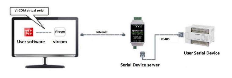
Click on "Serial Port & Device Management" on the Vircom main interface, then click "Add" and select to add COM2. Among them, COM2 is the newly emerging COM port on the computer.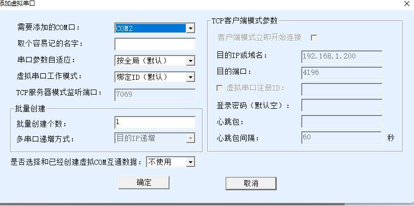
Then enter the device management and double-click the device that needs to be bound to COM2. As shown in the diagram, select COM2 from the Virtual Serial Port list in the top left corner. Then click on "Modify Setting" and then click on "Restart Device". Return to the main interface of Vircom. It can be seen that COM2 has been connected to the device whose IP is 192.168.1.200. In this case, COM2 can be used instead of SSCOM2 for communication.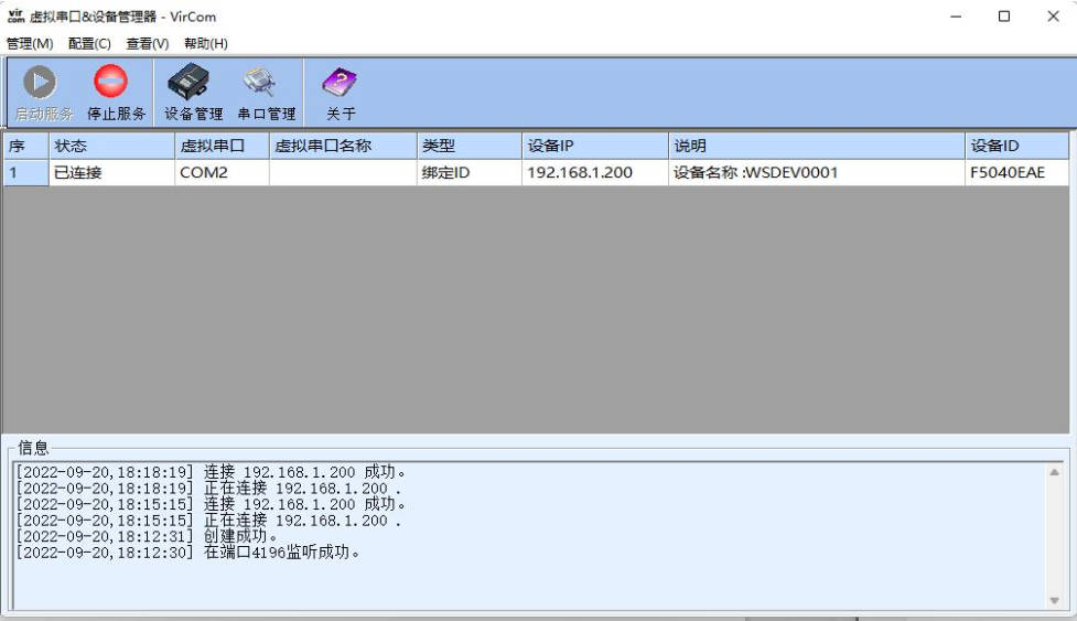
Open SSCOM to simulate the user's serial port program, open COM2 (the virtual serial port above), open another SSCOM to simulate a serial port device, and open COM3 (hardware serial port). At this time, the link for COM2 to send data is as follows: COM2 —> Vircom —> the network port of the serial server —> the serial port of the serial server —> COM3. Conversely, data can also be transmitted from COM3 to COM2: COM3 —> the serial port of the serial server —> the network port of the serial server —> Vircom —> COM2. As shown in the figure below, both parties send and receive data. If COM4 is replaced with the user serial device, then COM5 can realize the communication with the user device.
MODBUS TCP Test
By default, the data between the serial port and network port is transparently transmitted. If you need to implement Modbus TCP to RTU conversion, you need to select the Transfer protocol as "Modbus TCP<-->RTU" in the Device Settings dialog, as shown in the diagram below. In this case, the device port automatically changes to 502. Users can connect their Modbus TCP tool to the IP of the serial port server on port 502, and the Modbus TCP commands they send will be converted to RTU commands and outputted through the serial port. For example, if the serial server's Ethernet port receives a Modbus TCP command of 00 00 00 00 00 0601 03 00 00 0a, the serial port outputs the command of 01 03 00 00 00 0a c5 cd. Note: The serial port may send multiple 01 03 00 00 00 0a c5 cd commands because the default Modbus adopts the storage mode, which will automatically poll the query commands. How to switch to non-storage mode will be explained later.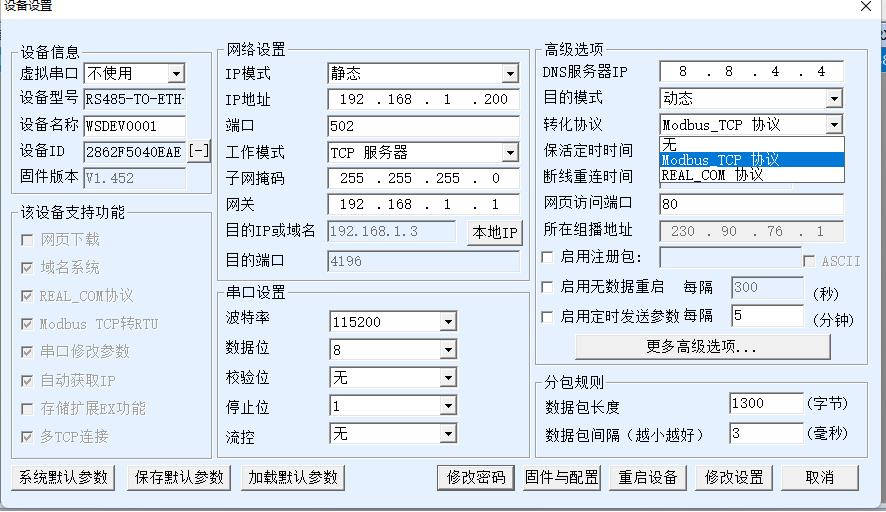
If the user's Modbus TCP software is used as a slave station (Slave), it is necessary to select the conversion protocol, then change the working mode to the client, the destination IP to the IP of the computer where the Modbus TCP software is located, and the destination port to 502, as shown in the figure below.
WEB Configuration
Using Vircom, you can search for and configure device parameters in different network segments. For Web configuration, you must first ensure that the computer and the serial server are in the same IP segment, and you need to know the IP address of the serial server in advance. But Web configuration can be done on any computer without Vircom. (Different products have different web interfaces)
1. Enter the IP address of the serial server in the browser, such as http://192.168.1.200 to open the following web page:
2. Enter password in "Password": There is no login password set by default in the factory, you can enter a password at will, and click the Login button to log in. After setting the password to log in, the settings at "Modify Web Login Key" will take effect: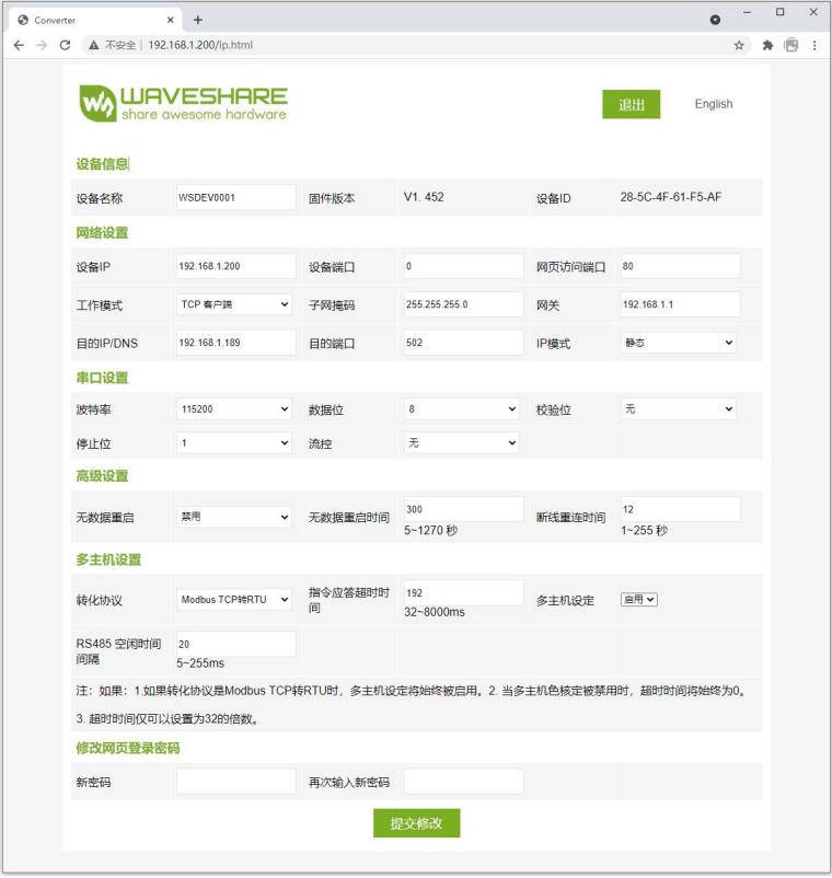
3. The serial server parameters can be modified on the web page that appears. For the relevant parameters, please refer to Table 4 for the meaning of the parameters.
4. After modifying the parameters, click the "Submit" button.
5. If the configuration web page files are overwritten during the configuration and downloading of MQTT and Jetson Modbus firmware, causing the configuration web page to be inaccessible, please follow these steps to re-download the web page files:
- Configuration interface Web file to RS485 TO ETH (C):

Resources
Document
Software
Related Application Case
RS485 TO ETH Connect Alibaba Cloud and EMQX via MQTT
FAQ
Software Issues
Question: RS485 TO ETH (C) LINK is yellow, what should I do if I cannot access the network?
- Set static IP, for example:
RS485 TO ETH (C) is set to 192.168.1.200, port number is 1111;
The computer is set to 192.168.1.199, port number is 1111;
- Test with the TCP server shared by the Internet community: 45.79.112.203, port number is 4242
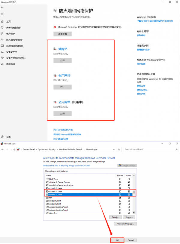
- Please add SSCOM to the firewall, otherwise the firewall will block TCP connections; Or turn off all firewall tests on the computer:
- If necessary, restore the module to factory settings.
- The gateway such as the switch or router is abnormal, and there is a network environment issue. Please replace the network environment for testing
The detailed data is as follows:
1) Short the NC pin for 5 seconds: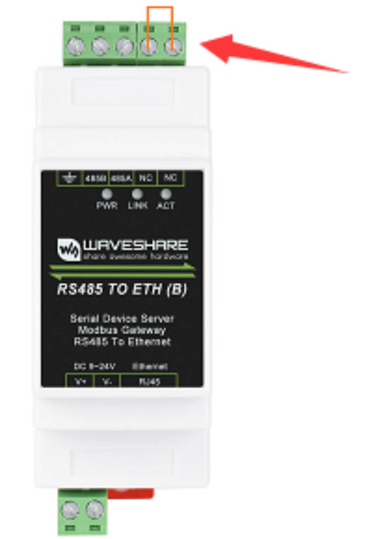
2) Get the default parameters and modify the settings: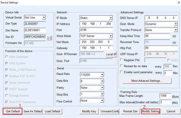
Question: What is the default access IP of the webpage?
- The default is 192.168.1.200~192.168.1.207;
- If the factory settings have been restored, the default IP is 192.168.1.254.
- If it doesn't work, please use VirCom configuration software to search for the device first to get the corresponding IP:
- If it still doesn't work, please restore the module to factory settings, and then flash the corresponding webpage.
Question: What should I do if the web configuration interface cannot be opened?
Other firmware, such as MQTT and Jetson Modbus, which are downloaded for configuration, overwrite the configuration page file, you need to re-download Configuration interface Web file to RS485 TO ETH (C):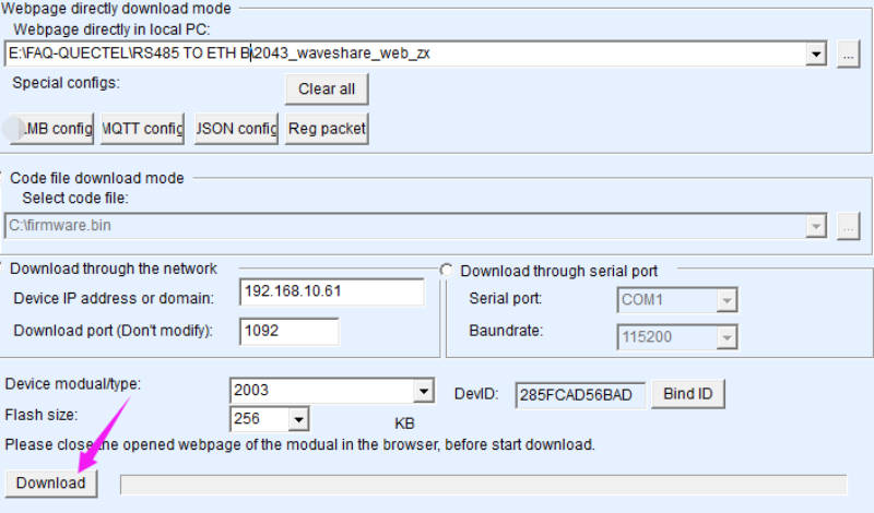
Question: Can the RS485 interface connect to multiple RS485 devices externally?
1. Multiple RS485 devices can be cascaded, and external RS485 devices need to be connected by handshake cascade as shown in the following figure: 
2. Up to 32 RS485 devices can be connected, and the RS485 to Ethernet gateway itself does not directly process the ID of the Modbus RTU, but instead maps the ID of the Modbus RTU device to the Modbus TCP protocol for communication through configuration, requiring the ID to be configured on the Modbus end device
3. If it is a Modbus rtu/645 application, it supports up to 25 registers.
Question: How to establish communication between RS485 TO ETH (C) and Modbus device?
1) Connect RS485 TO ETH (C) and Modbus device.
2) Configure the IP address and port number of RS485 TO ETH (C) to ensure it is connected to the local network.
3) Combined with the Specification of the Modbus sensor device, the key parameters such as baud rate and command (address code, function code) can be read: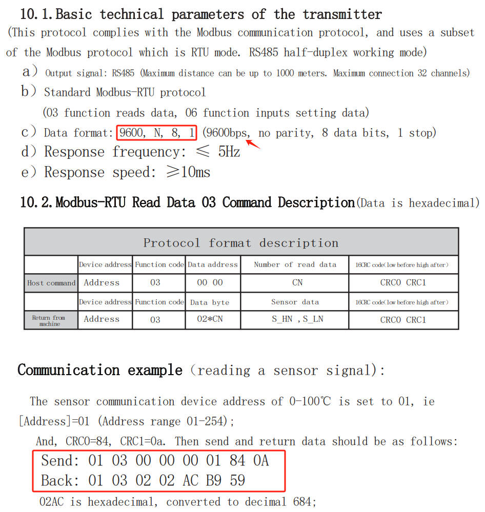
4) Configure the corresponding parameters in the VirCom or Web management interface, for example, set the baud rate to 9600, no check by default, 8 data bits, 1 stop bit: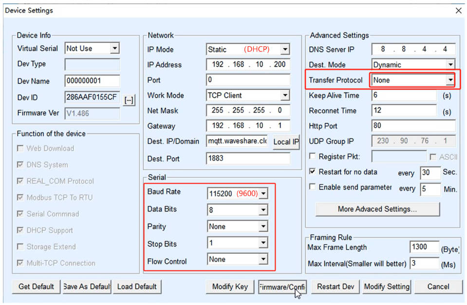
5) Use the None data transparent transmission mode to send the corresponding "hex" request data frame to the Modbus device, and select hex data transmission and hex display in the serial port assistant
UART sends 01 03 00 00 00 01 84 0A
ETH receives 01 03 02 02 AC B9 59
6) It can also be set to Modbus RTU to Modbus TCP mode; Converts Modbus TCP packets to Modbus RTU, receives the Modbus RTU response from the device, and converts it back to the Modbus TCP format.
UART sends 01 05 00 00 00 00 CD CA
ETH receives 00 00 00 00 00 06 01 05 00 00 00 00
Question: What should I do if I can't receive data and the communication is abnormal?
- Check the network (ETH)
1) Check the status of the indicator light. If the link light is constantly blue, it indicates that the TCP channel has been established; The Vircom software automatically searches and checks, and the TCP is established, indicating that the channel is established;
2) If the link light is not blue always on, but yellow-green/not on, then first log in to the VirCom software/Web page to see if you can log in, ping the device IP of the device to check if it is accessible? If it can be searched and pinged, it indicates that the device has not crashed. The host computer software will connect the IP and port of the device to see if it can be connected normally;
3) When a TCP connection channel is established, there is no data coming up. Based on the above judgment in 1), it is found that the TCP channel has been established but no data has come up, which needs to be investigated; 4) RS485 TO ETH (C) is set to 192.168.1.200 port number 1111; the computer is set to 192.168.1.199 port number 1111;
5) The host computer on the network is not sending data normally? You can configure network heartbeat packet verification, and if it is normal, it will deliver data regularly;
6) SSCOM needs to be added to the firewall, otherwise, the firewall will block the TCP connection, or close all firewall tests on the computer.
- Check the device (RS485)
1) Confirm hardware connections such as serial devices and check that your gateway and energy meter are properly connected. Ensure that the power and data cables are connected correctly and that there are no loose connections.
2) The serial terminal device received data and did not answer properly? Then it is necessary to monitor the data of the serial port device for judgment. Find a 485 to USB serial port cable and connect it to the interface of the 485 device to the computer USB. The computer maps a COM port, opens the serial port debugging assistant software, sets the serial port parameters to be consistent, inputs the corresponding COM port, and monitors the data of the 485 device to have a look. 485 wiring: T+ --A T- --B;Check whether the commands received on the 485 side are correct. If the correct commands are issued, check whether the 485 device responds normally.
3) Confirm the baud rate, data bits, stop bits, and other serial parameters configuration: the baud rate should be configured according to the access RS485 device being connected, and commonly used ones are 9600 and 115200; You can refer to the device manual or contact RS485 device technical support for confirmation; If set to Modbus mode, please confirm if the function code matches.
Question: How can I change the login password of the webpage?
- By default, there is no password, log in directly to the main page, and modify the login password at the bottom of the webpage, input new password in "New Key" (123456) and confirm it in "Input Key Again";
- After the change, you can't log in with an empty password or other passwords; you can log in with 123456 and the change is successful.

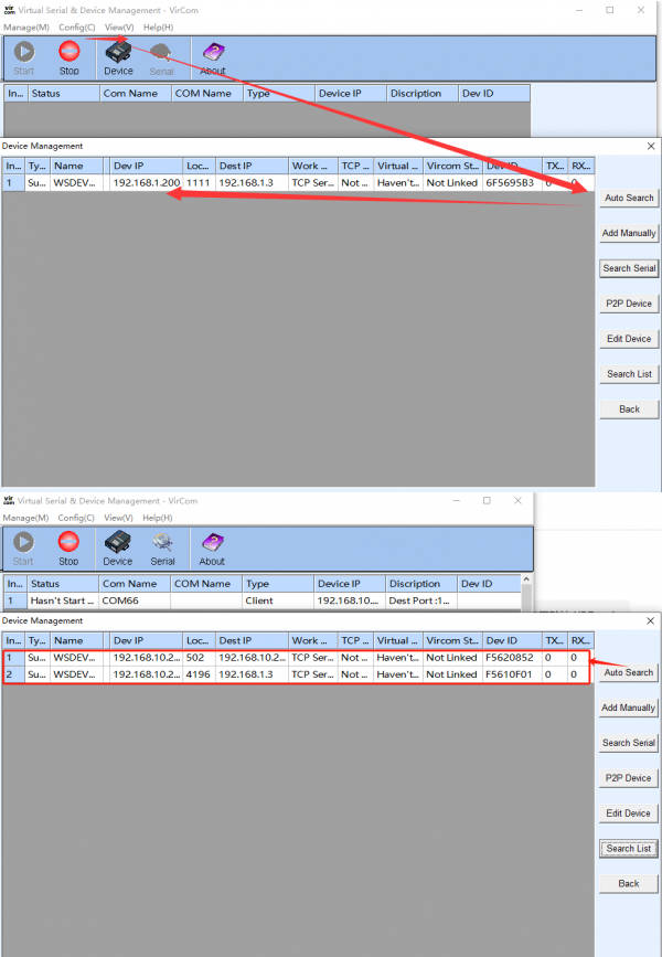
Question: How do you use two modules, one as a server and the other as a client?
- Connect both modules and the computer to the same gateway such as switch or router, so that they are in the same LAN, and set all devices to the same subnet IP (e.g. 192.168.200.XXX).
- Set one module as the client and the other module as a server, the destination IP and port number of the client is the local IP and port number of the server:
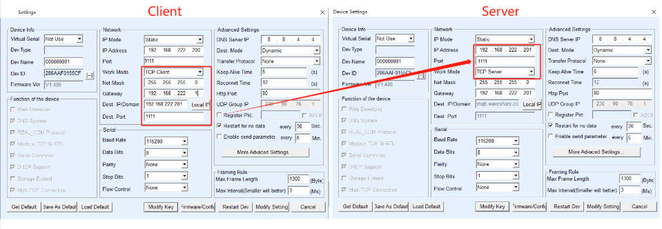
- After the configuration is OK, the data received from the serial port of the client will be transmitted to the serial port of the server, and vice versa
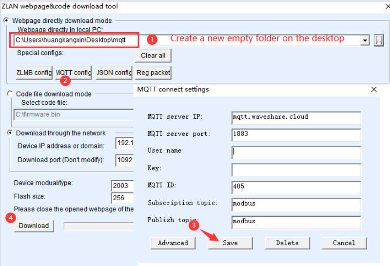
Question: Why my MQTT communication is abnormal?
- Please test by replacing a different MQTT server.
- Maybe your MQTT firmware configuration is wrong, please refer to the following steps to configure:
Question: How to deal with packet loss?
- On the network side, you can use Wireshark software to capture network packets exchanged between the host computer and the gateway. This is usually done when the host computer software is directly connected to the gateway, or through a mirroring switch (HUB connector) to capture packets and observe the data transmission and reception.
- On the serial port side, you can monitor by finding a 485 to USB serial cable and connect it to the interface of the 485 device to the computer USB. The computer maps a COM port, opens the serial port debugging assistant software, sets the serial port parameters to be consistent, inputs the corresponding COM port, and monitors the data of the 485 device. 485 wiring: T+ --A T- --B; Check whether the commands received on the 485 side are correct. If the correct commands are issued, check whether the 485 device responds normally.
Question: For a storage-type Modbus gateway and a non-storage-type Modbus gateway, where the device is a slave for the client, a simple Modbus TCP conversion, configurable Modbus gateway, what is the difference between these?
- Storage-type Modbus gateway: It can store the contents of the read registers inside the gateway, greatly improving the speed of Modbus TCP queries and providing superior performance when supporting multi host access.
- Non-storage-type Modbus gateway: Although storage-type Modbus has a fast response speed, some users do not want RTU devices to receive a large number of query instructions, which affects the internal processing speed of the instrument. In such cases, the storage-type function can be disabled.
- Simple Modbus RTU to TCP: There is no longer a multi-host mechanism.
- Device as a slave for the client: It is typically used in applications where a serial port host reads from a Modbus TCP slave.
- Configurable Modbus gateway function: According to the standard instructions you configure, periodically send commands via the serial port for data collection. Your network host then reads the collected data via Modbus TCP (programmable, supporting writing to registers with a recommended address quantity not exceeding 30).
Question: Which rails does S485 TO ETH (C) apply to?
It is suitable for 35mm standard (1mm thick) rails
Question: How does it automatically restart when encountering network failure?
You can set it as "Restart for no data". 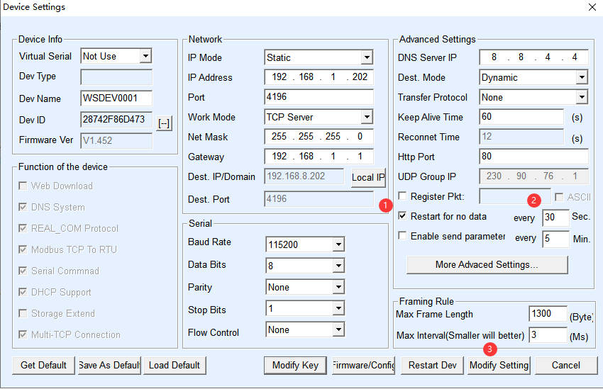
Question: Is there a description of the LED? Why is LINK sometimes green and sometimes blue?
- PWR Power indicator
- LINK
(1) The Link light is green when the network cable is connected.
(2) When a TCP connection is established (or in UDP mode), the Link is blue (actually with a faint green light). It can be used to determine whether the serial port server has established a communication link with the host computer software.
- ACT
(1) When the network port sends data to the serial port, the indicator light is green. The flashing time is 1 second longer than the actual communication time, which is more convenient to detect short data communication.
(2) When the serial port sends data to the network port, the indicator light is blue and green at the same time. Since the blue is brighter, if you see the blue light, it indicates that the serial port is returning data to the network port. This can be used to determine if the device is responding to commands from the host computer; if there is no response, it suggests that the serial port baud rate is incorrect or the serial port is not properly connected.
Question: Can I use the x03 or x10 command to write to the Modbus register?
Yes, the 03 function code is for reading, and the 10 function code is for writing. If it is a simple application that converts Modbus RTU to Modbus TCP, our device is a bidirectional transmission channel, as long as the terminal device supports 10 writing; If based on programmable functional applications, it supports writing 10 function codes. The specific operation is as follows: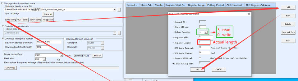
Question: Why is there packet loss? What is the packetization mechanism?
- The packetization mechanism is as follows:

- Under the same conditions, the larger the time interval, the less likely it is to lose packets.
- Increased processing time: Larger time intervals provide devices with more time to process received data, thereby reducing the possibility of packet loss due to insufficient processing speed.
- Reduced buffer overflow: Shorter intervals can cause buffers to fill up too quickly, while longer intervals give buffers a chance to empty data and avoid overflows.
- Improved data integrity: The larger the time interval, the more likely it is that data will be received and packetized in its entirety, reducing the risk of data fragment loss.
Hardware Issues
You need to use a router or switch that complies with the 802.3af/at network standard.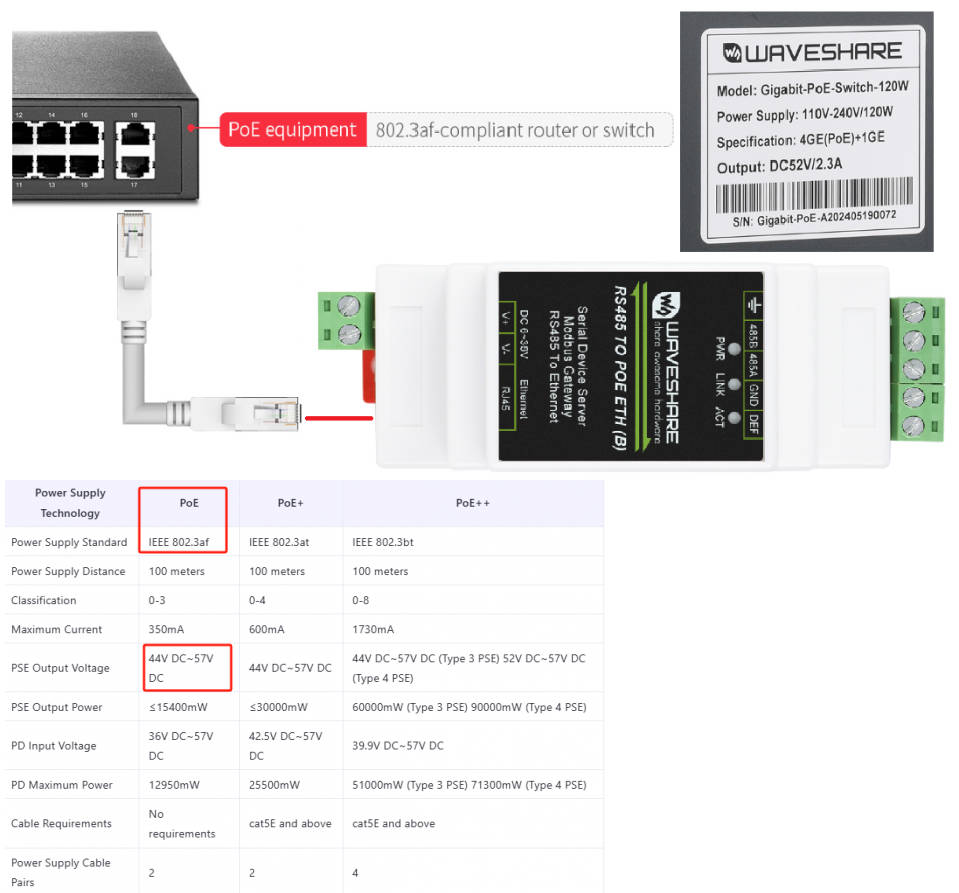
Question: The table says 10/100M adaptive RJ45 interface, does it support 100M network speed?
- No, it means it supports connecting to 10M or 100M switches; some Gigabit switches do not support it because the switches are not compatible.
- This means that the device has a 10Mbit Ethernet interface, and the upper limit speed of the device is determined by the serial port. In fact, the serial port speed cannot exceed 10Mbit/s.
Support
Monday-Friday (9:30-6:30) Saturday (9:30-5:30)
Email: services01@spotpear.com

[Tutorial Navigation]
- Overview
- Introduction
- Parameters Comparision
- Hardware Description
- Software Features
- Advanced Software Functions
- Applications
- Quick Test
- Resources
- FAQ
- Software Issues
- Question: RS485 TO ETH (C) LINK is yellow, what should I do if I cannot access the network?
- Question: What is the power of RS485 TO ETH (C)?
- Question: How to reset RS485 TO ETH (C) to factory settings?
- Question: What is the default access IP of the webpage?
- Question: What should I do if the web configuration interface cannot be opened?
- Question: Can the RS485 interface connect to multiple RS485 devices externally?
- Question: How to establish communication between RS485 TO ETH (C) and Modbus device?
- Question: What should I do if I can't receive data and the communication is abnormal?
- Question: How can I change the login password of the webpage?
- Question: How do you use two modules, one as a server and the other as a client?
- Question: Why my MQTT communication is abnormal?
- Question: How to deal with packet loss?
- Question: For a storage-type Modbus gateway and a non-storage-type Modbus gateway, where the device is a slave for the client, a simple Modbus TCP conversion, configurable Modbus gateway, what is the difference between these?
- Question: Which rails does S485 TO ETH (C) apply to?
- Question: How does it automatically restart when encountering network failure?
- Question: Is there a description of the LED? Why is LINK sometimes green and sometimes blue?
- Question: Can I use the x03 or x10 command to write to the Modbus register?
- Question: Why is there packet loss? What is the packetization mechanism?
- Hardware Issues
- Support