


- sales/support
Google Chat:---
- sales
+86-0755-88291180
- sales01
sales@spotpear.com
- sales02
dragon_manager@163.com
- support
tech-support@spotpear.com
- CEO-Complaints
zhoujie@spotpear.com
- Only Tech-Support
WhatsApp:13246739196
- Purchase/Shipping/Refund
WhatsApp:13424403025
- HOME
- >
- ARTICLES
- >
- Jetson Series
- >
- Jetson Acc
Jetson Orin Nano JETSON-ORIN-CASE-A User Guide
How to Assemble
- Before assembling, you can first confirm that all the accessories are complete.
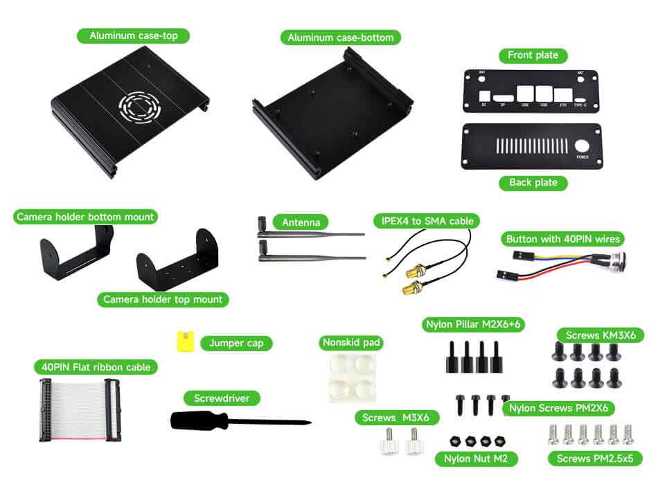
Among them, the list of ⑬ screw packages includes:- Jumper cap
- M3 screws
- M2 nylon pillar
- M2 nylon screws
- M2 nylon nut
- M3 black flat-head screws
- M2.5 silver screws
- Remove the base of the Jetson Orin Nano/NX and also remove the PCB antenna of the wireless card. Please keep the removed parts for future after-sales and service purposes to restore the board when needed.
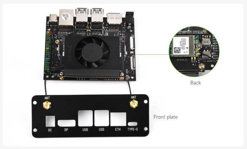
- Install the IPEX4 to SMA cable to the front plate. To fix the SMA connector, you need to unscrew the fixed nut of the cable and lock it on the outside of the front plate. The other end of the IPEX4 to SMA cable cable is connected to the wireless card on the back.
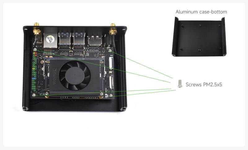
- Fix the Jetson Orin Nano/NX module to the aluminum bottom case with M2.5 silver screws, and simultaneously fix the front plate to the aluminum bottom plate with M3 black flat-head screws.
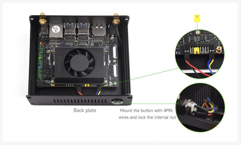
- Insert a jumper cap into the AUTO ON and DIS pins on the module. Unscrew the nut with the LED button and secure it to the back plate. Connect the button wires to the PWR BTN/GND and LED pins on the module.
- Note that the red wire should be connected to LED+, the black wire to LED-, and the yellow and blue wires are for the button, with no specific order required.
- After connecting the button, use M3 black flat-head screws to secure the lower part of the back plate to the aluminum bottom case.
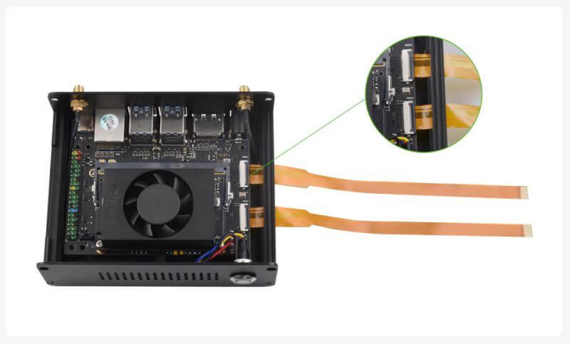
- If you need to connect a camera, thread the camera ribbon cable through the hole on the right side, securing it to the camera interface. Ensure that the metal contacts of the ribbon cable are facing downward.
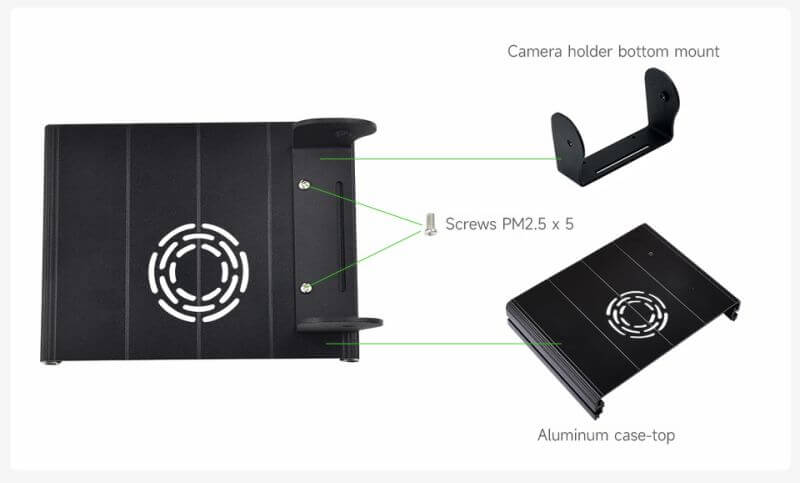
- If you need to connect a camera, secure the camera holder bottom mount to the aluminum top case using M2.5 silver screws.
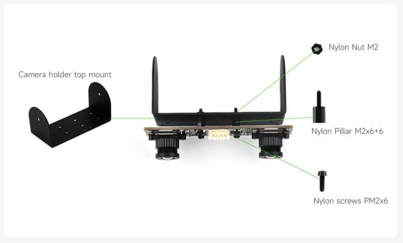
- If you need to connect a camera, use the provided nylon screw set to secure the camera to the camera holder top mount. Make sure to insert nylon pillars between the camera and the bracket to prevent the camera from short-circuiting.
- Please note that you should not use metal screws in this step. Using metal screws could lead to a short circuit with the camera, potentially damaging the equipment.
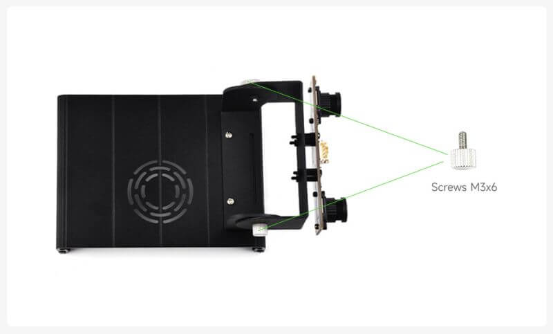
- Fix the camera holder top mount onto the camera holder bottom mount and tighten them together using M3 screws. During use, users can loosen the screws to adjust the bracket's angle as needed.
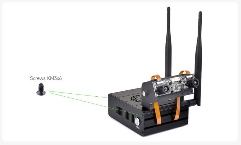
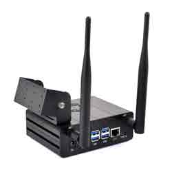
- Install the aluminum top case onto the bottom case, ensuring the correct orientation. Then, use M3 black flat-head screws to securely fasten the upper side of the side panels. Connect the other end of the camera ribbon cable to the camera, and attach the antenna.
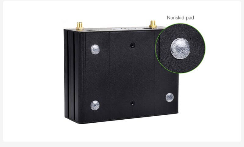
- Finally, users in need can apply non-slip rubber pads to the bottom.
TAG:
Xiaozhi-AI-video-tutorial-2
LuckFox Pico
LuckFox Pico Mini
Raspberry Pi 0.85inch LCD
Sensor
RV1103
Raspberry Pi 1.3inch LCD
ESP32-S3 1.69inch LCD Display With QST Attitude Gyro Sensor QMI8658C For Arduino Python
5inch Raspberry Pi Touch Display 2 5-inch Official Original 720x1280 LCD DSI/MIPI Screen
ESP32 Development Board WiFi+Bluetooth Ultra Low Power Dual Core ESP 32S ESP 32 Similar ESP8266
ESP32 desktop trinket
USB To CAN
WiFi6
ESP32 1.54 inch E-Paper Smart Watch display Screen 200x200 Ultra-low power For Arduino/Micropython/RTOS For Watchy
Raspberry Pi Pico 2 RP2350A USB-C Mini Development Board
Raspberry Pi 2inch LCD
Jetson Nano 4G module
Install Espressif IDF Plugin Tutorial User Guide
Raspberry Pi RP2040 Camera
MPS2.5G Raspberry Pi 5 PCIe to NVME SSD And 2.5G Ethernet RJ45 HAT RTL8125 2280 2242 2230
.jpg)
TAG:
Milk V Duo UART
EVAL-ADXL354CZ
USB to SPI
Jetson Orin 5G/4G/3G expansion board GNSS GPS SIM8260G-M2 SIM8262E-M2
1.69inch LCD TouchScreen Display 240×280 ST7789 Arduino Raspberry Pi ESP32S3 Pico STM32
Spotpear
Horizon Robotics RDK Ultra D-Robotics Sunrise
spotpear
Raspberry Pi Official Original POE Plus HAT Injector 30W Power Over Ethernet 802.3af/at For Pi5 Onboard RGB LED For RJ-45 EIA 568A/568B Port
3.5 inch LCD
Black
Spotpear
Raspberry Pi 5
ESP32-S3 USB Dongle
CV1800B
Raspberry Pi 5 inch DSI LCD Display MIPI 800x480 Capacitive TouchScreen
CAM-GC2083
Raspberry Pi 5 inch DSI IPS LCD Display MIPI 800x480 Optional Touchscreen
Raspberry Pi 5 POE
T-Deck ESP32-S3 SX1262 LoRa LoRaWAN 2.8 inch LCD TouchScreen Display Blackberry KeyBoard LILYGO Arduino