


- sales/support
Google Chat:---
- sales
+86-0755-88291180
- sales01
sales@spotpear.com
- sales02
dragon_manager@163.com
- support
tech-support@spotpear.com
- CEO-Complaints
zhoujie@spotpear.com
- Only Tech-Support
WhatsApp:13246739196
- Purchase/Shipping/Refund
WhatsApp:13424403025
- HOME
- >
- ARTICLES
- >
- Common Moudle
- >
- ESP
T-Camera-S3-0.96inch User Guide
【Examples】
examples examples
├─AllFunction                       # Full function test
├─MinimalCameraExample              # Minimal camera example
├─MinimalPowersExample              # Minimal PMU operation example
├─MinimalScreenExample              # Minimal screen example
├─MinimalSoundDetectionExample      # Minimal ambient sound detection example
└─MinimalVoiceWakeupExample         # Minimal voice wakeup example
【Software】
- Installation VisualStudioCode and Python
- Search for PlatformIO plug-in in
VisualStudioCodeextension and install it. VisualStudioCodeneeds to be restarted after installation.- VisualStudioCode, select File in the upper left corner of VisualStudioCode-> Open Folder-> Select LilyGo-Cam-ESP32S3 directory.
- Click the platformio.ini file and cancel the sample lines to be used in the platformio column. Please ensure that only one line is valid.
- Click the (√) symbol in the lower left corner to compile.
- Connect the board to the computer USB.
- Click (→) to upload the firmware.
- Click (plug symbol) to monitor serial output.
- Use
AllFunctionandMinimalSoundDetectionExampleExample, need to upload additional model files, according to the following steps.- Click PlatformIO(bee icon) to the left of VisualStudioCode.
- Select
t-cameras3 - Select
Platform - After ensuring that the board is connected to USB, click
Upload Filesystem image
【Note】
- Can I use
Arduino IDE?AllFunctionandMinimalSoundDetectionExampleexample is not acceptable, because you need to upload model files and custom partition tables. At present, Arduino IDE does not support custom partition tables and uploading model files (the time for writing README is 20220930).- The remaining example is that Arduino IDE can be used.
- The board is integrated with PMU(Power management chip), which has short-circuit and overload protection. By default, PWRKEYneeds to press for 6 seconds to turn off the power supply of the board, and press PWRKEY for 128 milliseconds to turn on the power supply. If you need to modify the power-off pressing time, please refer to MinimalPowersExample.
- If the charging function is needed, the
PMUTS Pindetection function needs to be turned off. By default, there is no NTC sensor on board, so it is necessary to disable TS Pin detection in order to use the charging function normally. If the TS Pin detection function is not turned off, the PMU charging indicator light will blink after inserting the battery, and charging will be disabled at this time. - The external 5 Pin expansion socket of the board, 5V is shared with
PMUSYS, please do not externally connect an external power supply load larger than 600mA, and the 3.3V is powered by PMUDCDC3, and the voltage can be adjusted, and the maximum output current should not exceed 1A - All peripherals on board except OLED can turn off the power supply.
- When the sketch cannot be uploaded, please press and hold the BOOT button on the board, and then insert USB. At this time, you should be able to see the port in the device manager of the computer, and then click Upload Sketch again.
- When the power channel of ESP32S3 is turned off by mistake, please insert USB, then press and hold the BOOT button of the board, and then press and hold the PWRKEY button. At this time, the board enters the download mode, and the sketch can be uploaded normally.
- Please understand the risks before changing the peripheral voltage, otherwise, please do not try to change the voltage of the camera and other onboard equipment, which may cause permanent damage.
- When you think there is something wrong with the board, you can try to burn our factory firmware for testing, and you can rule out whether it is a hardware problem first. FactoryFirmware
【Pins】
Camera
| PWDN | Reset | XCLK | SDA | SCL | VSYNC | HREF | PCLK |
|---|---|---|---|---|---|---|---|
| N/A | 39 | 38 | 5 | 4 | 8 | 18 | 12 |
| D9 | D8 | D7 | D6 | D5 | D4 | D3 | D2 |
| 9 | 10 | 11 | 13 | 21 | 48 | 47 | 14 |
| OLED/PMU/PIR | SDA | SCL | PMU IRQ | PIR |
|---|---|---|---|---|
| 7 | 6 | 2 | 17 | |
| Microphone | WS | DATA | CLK | |
| 42 | 41 | 40 |
Power Channel:
| PMU Channel | Microphone | OLED | Camera | Pir |
|---|---|---|---|---|
| BLDO1 | DCDC1 | ALDO1/ALDO2/ALDO4 | ALDO3 |
TAG:
5inch
EchoEar 1.85 inch Round TouchScreen 1.85inch QSPI LCD 360*360 CST816T ST77916
Raspberry Pi Pico DVI
Pi5
800×480
X1005 Raspberry Pi 5 PCIe to M.2 NVMe Dual SSD Adapter Board HAT Pi5 Double 2230/2242/2260/2280
Raspberry Pi DSI
SpotPear
ESP32-C5 2.8inch LCD Display Capacitive AI Development Board 240×320 2.8 inch TouchScreen
Raspberry Pi UGV Rover ROS2 PT AI OpenCV Robot Car MediaPipe
ESP32 S3 Development Board 1.75 inch AMOLED Display TouchScreen SD slot 6-axis sensor Xiaozhi AI Deepseek
Arducam 64MP Camera
Raspberry Pi ZERO Camera
Raspberry Pi Mipi display
Spotpear
ESP32-S3 SIM7670G 4G Development Board With Camera LTE Cat-1/4G/GNSS/GPS Global Band Portable WIFI
NVIDIA
GC2083
ESP32-S3 ST7789
Raspberry Pi ST7789
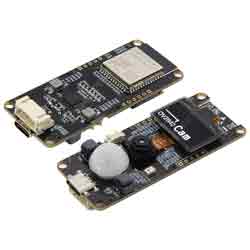
ESP32 S3 Development board T Camera S3 With 0.96inch OLED display screen OV2640Camera WiFi Bluetooth
TAG:
Raspberry Pi 10.1 inch LCD Display Capacitive TouchScreen 1920x1200 Jetson Nano mini Computer PC
USB Monitor
Raspberry Pi 5 PCIe 2CH M.2 NVMe SSD HAT (B) Pi5-PCIe-2280-2242-2230
Speaker Buzzer Luckfox-Pico-Ultra
ESP32 S3 Development Board 7 inch LCD Capacitive Touch Screen 7inch Display 800×480 N16R8
DeepSeek AI Voice Chat ESP32 Development Board 3.5 inch TouchScreen Display 320x480
RS422 to CAN
SpotPear
Aluminum Heatsink
25mm Telephoto CS Lens Raspberry Pi High Quality Camera Global Shutter Camera
JETSON NANO IO BASE Board
Seeed Studio XIAO ESP32C3 Wi-Fi Arduino
Raspberry Pi RTC WatchDog
Raspberry Pi 5 Silver-Shadow Case
Raspberry Pi 7.5 inch e-Paper link (H) RYBW 800x480 For Arduino / Jetson Nano / STM32
Raspberry Pi 5 Case
Raspberry Pi Transparent Screen
Raspberry Pi Power Relay Board
JLINK OB
Raspberry Pi Compute Module 5 CM5 PoE BASE A IO Board