


- sales/support
Google Chat:---
- sales
+86-0755-88291180
- sales01
sales@spotpear.com
- sales02
dragon_manager@163.com
- support
tech-support@spotpear.com
- CEO-Complaints
zhoujie@spotpear.com
- Only Tech-Support
WhatsApp:13246739196
- Purchase/Shipping/Refund
WhatsApp:13424403025
PICO-Cam-A Guide
Resource
Demo
Schematic
Official Resources
Raspberry Pi Official Datasheet
- Raspberry Pi Pico Get Started MicroPython
- Related Raspberry Pi Books Download
- Get Started With Pico Manual
- Pico C SDK User Manual
- Pico Python SDK User Manual
- RP2040 Datasheet
- Raspberry Pi Pico Schematic
- Pico Pinout
- Pico Datasheet
- Rp2040 Datasheet
- Hardware Design Manual
Raspberry Pi Open-source Demo
Development Software
Overview
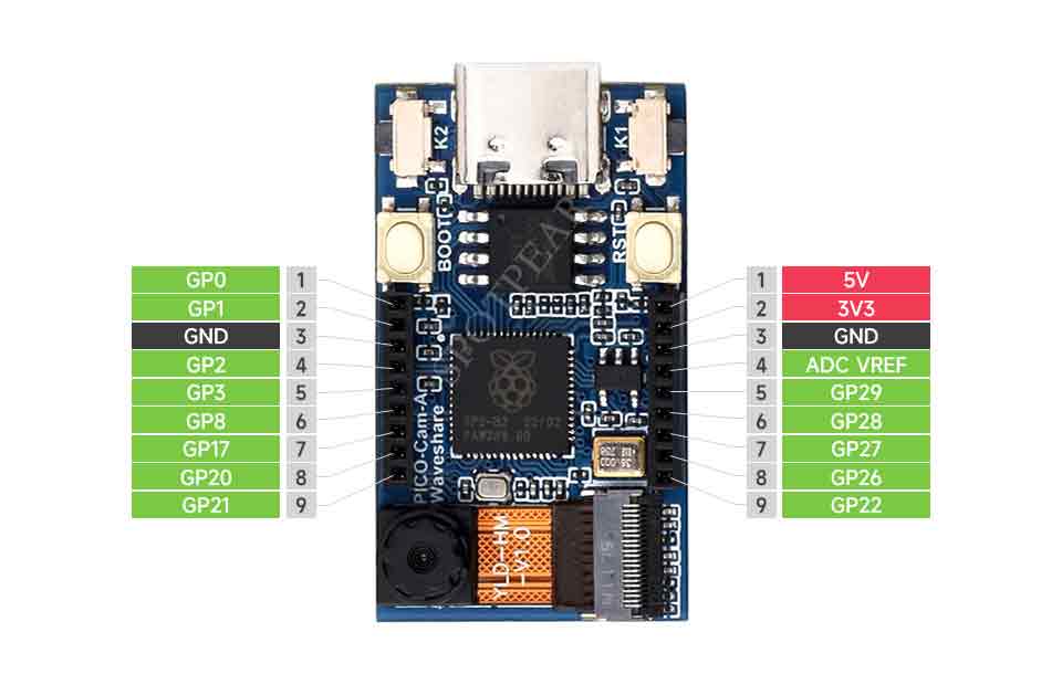
PICO-CAM-A is a high-performance microcontroller camera development board designed by Waveshare. With an HM01B0 grayscale camera and a 1.14-inch IPS display screen, it also has onboard 13 GPIO pin headers and a Debug interface, making it easy for users to develop with better integration into applications.
Features
- RP2040 microcontroller chip designed by Raspberry Pi in the United Kingdom.
- Dual-core Arm Cortex M0+ processor, flexible clock running up to 133 MHz.
- 264KB of SRAM, and 16MB of onboard Flash memory.
- Type-C connector, keeps it up to date, easier to use.
- On-board HM01B0 grayscale camera.
- Onboard 1.14inch 240×135 pixels 65K colorful IPS LCD for clear color pictures.
- USB 1.1 with device and host support.
- Low-power sleep and dormant modes.
- Drag-and-drop programming using mass storage over USB.
- 13 × multi-function GPIO pins.
- Accurate clock and timer on-chip.
- Temperature sensor.
- Accelerated floating-point libraries on-chip.
- 8 × Programmable I/O (PIO) state machines for custom peripheral support.
Parameters
| LCD Specifications | |||
| Controller | ST7789V | Resolution | 135(H)RGB x 240(V) |
| Communication Interface | SPI | Display Dimensions | 14.864(H)x 24.912(V)mm |
| Display Panel | IPS | Pixel Size | 0.1101(H)x 0.1035(V)mm |
Pinout
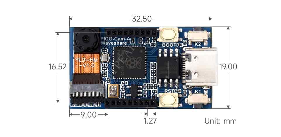
Dimensions
Get Started with Pico
Introduction
C/C++ Series
Open-source Demo
Sample Demo
C Demo
Demo Explanation
Demo Explanation
This example primarily involves capturing images through the camera and displaying them on a 1.14-inch LCD. The demo utilizes multi-core processing, with Core 1 responsible for acquiring image data and image processing, while Core 0 handles the image display.
Core 1 Demo Explanation
- Data Pushing
multicore_fifo_push_blocking() is a function provided by Pico SDK for pushing data to the FIFO (First In, First Out) queue of the multi-core system. Here, Core 1 will push the data to FIFO, and Core 0 will block to wait for the FLAG_VALUE data from Core 1.
multicore_fifo_push_blocking(FLAG_VALUE);
- Wait for Data
Core 1 blocks and waits for the data from Core 0.
uint32_t ack = multicore_fifo_pop_blocking();
- LCD Initialization
Call DEV_Module_Init() to initialize the pins and buttons related to the LCD, and call LCD_1IN14_V2_Init() to initialize the LCD.
DEV_Module_Init();
LCD_1IN14_V2_Init(HORIZONTAL);
LCD_1IN14_V2_Clear(BLACK);
UDOUBLE Imagesize = LCD_1IN14_V2_HEIGHT * LCD_1IN14_V2_WIDTH * 2;
UWORD *BlackImage;
if ((BlackImage = (UWORD *)malloc(Imagesize)) == NULL)
{
    printf("Failed to apply for black memory...\r\n");
    exit(0);
}
- Display Image
Call Paint_DrawImage() to draw imahes, and call LCD_1IN14_V2_Display() to display the images on the LCD.
Paint_NewImage((UBYTE *)BlackImage, LCD_1IN14_V2.WIDTH, LCD_1IN14_V2.HEIGHT, 0, WHITE);
Paint_SetScale(65);
Paint_SetRotate(ROTATE_0);
Paint_DrawImage(gImage_waveshare, 0, 0, 240, 135);
LCD_1IN14_V2_Display(BlackImage);
DEV_Delay_ms(500);
- Camera Initialization
This code segment calls cam_config_struct() to initialize the camera configuration structure "config" and then proceeds to initialize the camera by calling cam_init().
struct cam_config config;
cam_config_struct(&config);
cam_init(&config);
- Image Processing
This code segment is a loop where the camera captures a frame in each iteration, processes the image, and ultimately stores the processed image data in "displayBuf". The "imageReady" flag is then set to 1, indicating that the image is ready for display.
while (true) {
    cam_capture_frame(&config);

    uint16_t index = 0;
    for (int y = 134; y > 0; y--) {
        for (int x = 0; x < 240; x++) {
            uint16_t c = image_buf[(y)*324+(x)];
            uint16_t imageRGB = (((c & 0xF8) << 8) | ((c & 0xFC) << 3) | ((c & 0xF8) >> 3));
            displayBuf[index++] = (uint16_t)(imageRGB >> 8) & 0xFF;
            displayBuf[index++] = (uint16_t)(imageRGB) & 0xFF;
        }
    }

    imageReady = 1;
}
Core 0 Demo Explanation
- Boots Core1
multicore_launch_core1 is the function provided by Pico SDK for booting Core 1 on the Raspberry Pi Pico. This code boots the function specified by Core 1 through calling multicore_launch_core1().
multicore_launch_core1(core1_entry);
- Wait for data
Core 0 blocks and waits for data from Core 1, if successfully received data FLAG_VALUE then send data to Core 1.
uint32_t ack = multicore_fifo_pop_blocking();
if (ack != FLAG_VALUE)
    printf("Error: Core 0 failed to receive acknowledgment from core 1!\n");
else {
    multicore_fifo_push_blocking(FLAG_VALUE);
    printf("Success: Core 0 Received acknowledgment from core 1!\n");
}
- Main Loop
Continuously checks the "imageReady" flag in the main loop. Once the flag is detected as 1, indicating that the image is ready for display, it calls LCD_1IN14_V2_Display() to show the image. After the display, it resets the "imageReady" flag to 0.
while (1) {
    if (imageReady == 1) {
        LCD_1IN14_V2_Display((uint16_t*)displayBuf);
        // Reset the imageReady flag after displaying the image
        imageReady = 0;
    }
    DEV_Delay_ms(1);
}
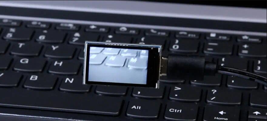
Run the Demo
- After programming the firmware and powering up, the PICO-Cam-A displays the boot-up screen and then shows the camera's captured images in real-time.
