




- sales/support
Google Chat:---
- sales
+86-0755-88291180
- sales01
sales@spotpear.com
- sales02
dragon_manager@163.com
- support
tech-support@spotpear.com
- CEO-Complaints
zhoujie@spotpear.com
- Only Tech-Support
WhatsApp:13246739196
- Purchase/Shipping/Refund
WhatsApp:13424403025
- HOME
- >
- ARTICLES
- >
- Common Moudle
- >
- UART Module
USB-TO-RS485 User Guide
Introduction
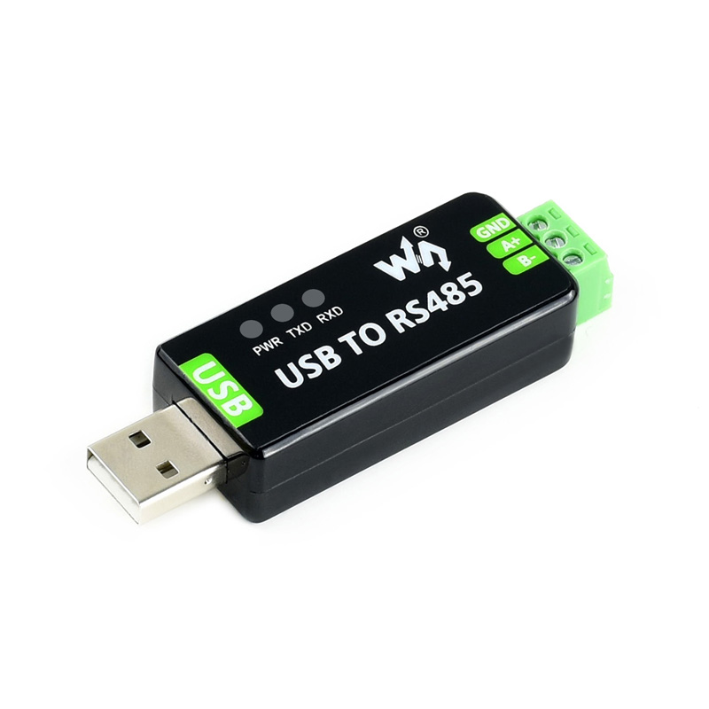
This is an industrial USB to RS485 converter with original FT232RL inside. It features embedded protection circuits such as lightning-proof, resettable fuse, ESD protection, and TVS diode, etc. It's pretty small in size.
Features
- USB to RS485 communication.
- Adopt original FT232RL, fast communicating, stable and reliable, better compatibility.
- Onboard TVS (Transient Voltage Suppressor), effectively suppresses surge voltage and transient spike voltage in the circuit, lightning-proof & anti-electrostatic.
- Onboard self-recovery fuse and protection diodes, ensure the current/voltage stable outputs, provides over-current/over-voltage proof, and improve shock resistance.
- 3x LEDs for indicating the power and transceiver status.
Specification
- Product type: industrial converter
- Baudrate: 300-921600bps
- Host port: USB
- Device port: RS485
- USB:
- Operating voltage: 5V
- Connector: USB-A
- Protection: 200mA self-recovery fuse, ESD protection
- Transmission distance: about 5m
- RS485:
- Connector: screw terminal
- Pins: A+, B-, GND
- Direction control: hardware automatic control
- Protection: 600W lightning-proof and surge-suppress, 15KV ESD protection (onboard 120R balancing resistor).
- Transmission distance: about 1200m (low rate)
- Transmission mode: point-to-multipoint (up to 32 nodes, it is recommended to use repeaters for 16 nodes or more).
- LED indicators:
- PWR: red power indicator, lights up when there is a USB connection and voltage is detected.
- TXD: red TX indicator, lights up when the USB port sends data.
- RXD: red RX indicator, lights up when the device ports send data back.
- Operating environment:
- Temperature: -15℃ ~ 70℃
- Humidity: 5%RH ~ 95%RH
- Operating system: Mac, Linux, Android, WinCE, Windows 10/8.1/8/7/XP
User guide
Driver installation
- Connect the module to host PC, check Device Manager, if the device is listed with the yellow exclamation mark, it means that the driver was not installed.

- Download the driver form #Resources, unzip, and install it.
- After installing, you can find that the mark disappeared and a COM device is listed

- You can download the software installation package on the official website WIKI, (here need to have the path) double click :
- Click "Extract":
- Click "Next":
- Check the box I accept this agreement (A) and click Next:
- Click Finish, at this point, check your computer's device manager and you can see that the port number is working properly.
Testing
- RS485
- You should prepare two RS485 devices.
- Connect A+ to A+, B- to B-, and connect them to host PC.
- Run SSCOM software to test.

- Expected result:

Resources
FAQ
Question:Can't be used on the non-windows system, how to solve it?
Question:Does it support Linux systems?
Question:What should I do if the RS485 short-range communication is abnormal?
Question:Does it support USB to RS232, RS485 and TTL at the same time?
Question:Does it support RS232, RS485 and TTL interchange?
Question:Does the module have an onboard 120-ohm balancing resistor?

Question:Why does it disconnect automatically after working for a period of time?
1. Power supply problems: The power supply for the FT232 must be stable; an insufficient or unstable power supply may cause automatic disconnection. Make sure the power supply you use can provide enough current and the voltage is stable. Please replace the USB port, USB 3.0 port is recommended, or try a different computer.
2. USB cable problem: Using a poor-quality USB cable or USB plug may cause distortion or interference with the electrical signal, which may lead to automatic disconnection. Use good quality USB cables or USB plugs whenever possible.
3. Driver problem: Make sure the driver you are using is the latest version and has been installed correctly, driver errors may cause automatic disconnection, uninstall the driver and reinstall the driver, or you can install the following driver to try; click to download.
4. Circuit interference: consider the device interference caused by the GND is also connected, check the ground current loop, while the USB shell is also grounded, if the circuit involves experience, you can use optical coupling in the middle of the device and USB TO RS485 to isolate it to avoid interference.
Question:Does it support Modbus?
- USB to RS485 supports Modbus and is a common Modbus communication method.

- Modbus is a communication protocol mainly used for communication between devices in the field of industrial automation. RS485 is one of the common physical layer transmission methods for Modbus. Therefore, converters/components that support the RS485 interface (including, of course, USB TO RS485) can usually also support the Modbus protocol.
- However, USB to RS485 only provides the physical layer conversion, i.e., converting the USB interface to the RS485 interface, while Modbus communication needs to be implemented at the protocol layer.
- When understanding Modbus protocol, you need to understand Modbus function codes and data format. Modbus has various function codes, and each function code corresponds to an operation, such as read coil status, read input status, read holding register, etc.
Question:Should RS485 communication connect to GND?
No, but it is more stable with a connection to the GND signal. For better performance, reliability, and anti-interference, it is recommended to connecting to GND in long-distance communication.
Support
Monday-Friday (9:30-6:30) Saturday (9:30-5:30)
Email: services01@spotpear.com

[Tutorial Navigation]
- Introduction
- User guide
- Resources
- FAQ
- Question:Can't be used on the non-windows system, how to solve it?
- Question:Does it support Linux systems?
- Question:What should I do if the RS485 short-range communication is abnormal?
- Question:Does it support USB to RS232, RS485 and TTL at the same time?
- Question:Does it support RS232, RS485 and TTL interchange?
- Question:Does the module have an onboard 120-ohm balancing resistor?
- Question:Why does it disconnect automatically after working for a period of time?
- Question:Does it support Modbus?
- Question:Should RS485 communication connect to GND?
- Support