


- sales/support
Google Chat:---
- sales
+86-0755-88291180
- sales01
sales@spotpear.com
- sales02
dragon_manager@163.com
- support
tech-support@spotpear.com
- CEO-Complaints
zhoujie@spotpear.com
- Only Tech-Support
WhatsApp:13246739196
- Purchase/Shipping/Refund
WhatsApp:13424403025
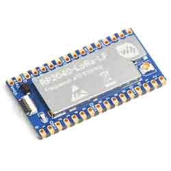
RP2040-LoRa Guide
Overview
Introduction
RP2040-LoRa is a LoRa development board using the new generation of SX1262 RF chip, which provides better performance than the SX127X series in power consumption, communication distance, and power efficiency. Adopts LoRa modulation technology to solve the problem in the traditional design solutions which can not balance distance, anti-interference, and power consumption at the same time. Combines with LoRa gateway for connecting Cloud Server such as TTN and ChirpStack for quick verification. Optional for LF/HF frequency band.
Features
- RP2040 microcontroller chip designed by Raspberry Pi in the United Kingdom.
- Dual-core Arm Cortex M0+ processor, flexible clock running up to 133 MHz.
- 264KB of SRAM, and 2MB of onboard Flash memory.
- Onboard FPC 8PIN connector, adapting USB Type-C port via adapter board.
- Castellated module allows soldering directly to carrier boards.
- USB 1.1 with device and host support.
- Low-power sleep and dormant modes.
- Drag-and-drop programming using mass storage over USB, up to 20 × multi-function GPIO pins.
- Supports FSK, GFSK, and LoRa modulation, featuring better anti-blocking and ultra-long distance communication.
- With -148dBm high reception sensitivity and programmable emit power up to 22dBm.
- Supports preamble detection, with CRC, up to 256-byte data packet engine.
- Comes with online resources and manual (example in C).
Specification
| Version | RP2040-LoRa-LF | RP2040-LoRa-HF |
| RF Chip | SX1262 | |
| Frequency Band | LF: 410 ~ 450MHz | HF: 850 ~ 930MHz |
| Emit Power | MAX@22dBm (adjustable) | |
| Emit Current | 107mA@22dBm | 118mA@22dBm |
| Receive Current | 5.3mA@125KHz | |
| Signal Modulation | LoRa/(G)FSK | |
| Operation Temperature | 0 ~ 60℃ | |
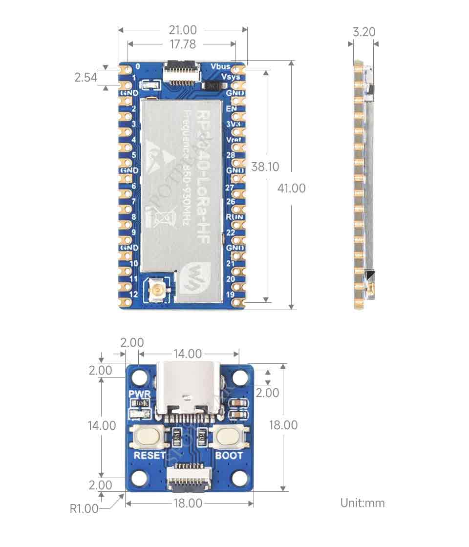
| Dimensions | 21.00 × 41.00mm | |
Hardware Description
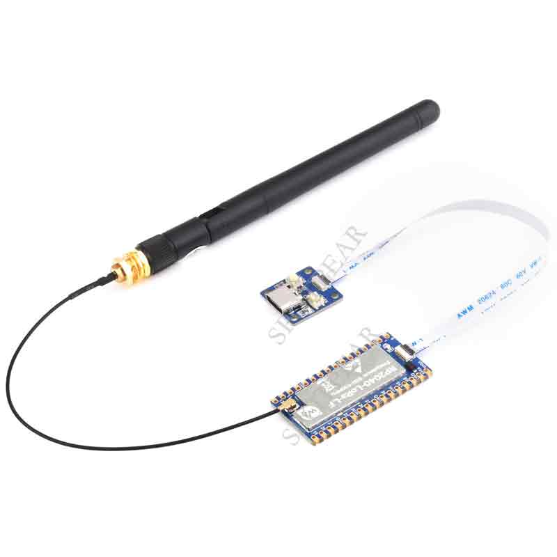
Hardware Connection
- RP2040-LoRa x 1 (included)
- Type-C USB cable x 1 (not included)
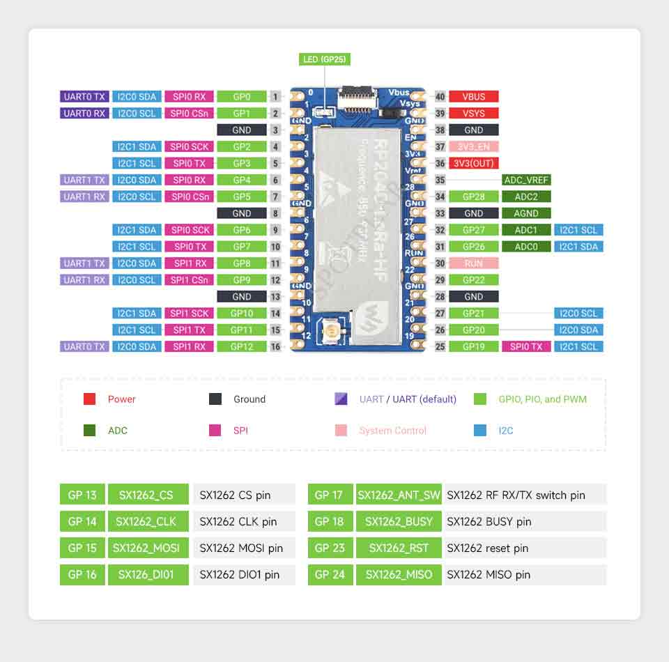
| SX1262 | Pico | Function |
| SX1262_DIO1 | GP16 | SX1262 interrupt output pin or special function pin |
| SX1262_RST | GP23 | Reset pin, low active |
| SX1262_MISO | GP24 | SPI MISO pin, slave device data output |
| SX1262_MOSI | GP15 | SPI MOSI pin, slave device data input |
| SX1262_CLK | GP14 | SPI SCK pin, slave device clock input |
| SX1262_CS | GP13 | SPI chip selection pin (low active) |
| SX1262_BUSY | GP18 | SX1262 BUSY Pin |
| SX1262_ANT_SW | GP17 | Switching between transmit and receive pins, open the transmission switch with a low level |
Pinout Definition
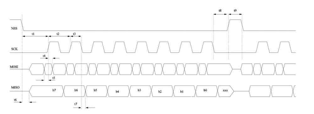
- The Raspberry Pi RP2040 uses the SPI bus to read and write the 36 registers of the SX1262 to complete LoRa wireless data transmission. The SPI bus frequency should be less than 18MHz. For specific SPI Timing Requires, see Chapter 8 Digital Interface and Control of the datasheet.
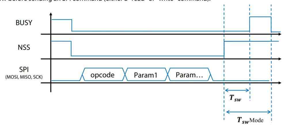
- The SPI bus writing a command to the LoRa chip will trigger the switching of the internal state machine mode. It should be noted that the low level of the BUSY pin indicates that the internal idle is allowed to receive commands, and the high level indicates that the internal occupied cannot receive the SPI command. The SPI bus needs to wait for the BUSY pin pull low again to continue reading and writing operations, TswMode is up to 3.5ms.
- SX1262 is a half-duplex LoRa RF chip, SX1262_ANT_SW is a transceiver switching pin, connected to pin GPIO17 of RP2040, when SX1262 is in transmitting state, pin GPIO17 should be kept low, and in other states it should be kept high.
Dimensions
LoRa & LoRaWAN
What is LoRa ?
Semtech's LoRa is a long-distance, low-power wireless platform for the Internet of Things (IoT), which generally refers to radio frequency chips using LoRa technology. The main features are as follows:
- The spread spectrum modulation technology adopted by LoRa (abbreviation of long-range) is derived from Chirp Spread Spectrum (CSS) technology, which is one of the long-distance wireless transmission technology and LPWAN communication technology. Spread spectrum technology uses bandwidth for sensitivity technology, Wi-Fi, ZigBee, etc. all use spread spectrum technology, but the characteristic of LoRa modulation is that it is close to the limit of Shannon's theorem, and the sensitivity can be improved with maximum efficiency. Compared with traditional FSK technology, at the same communication rate, LoRa is more sensitive than FSK by 8 ~12dBm. At present, LoRa mainly operates in the ISM frequency band of Sub-GHz.
- LoRa technology integrates technologies such as digital spread spectrum, digital signal processing, and forward error correction coding, which greatly improves the performance of long-distance communication. LoRa's link budget is better than any other standardized communication technology. Link budget refers to the main factor that determine the distance in a given environment.
- LoRa RF chips mainly include SX127X series, SX126X series, SX130X series, of which SX127X, SX126X series are used for LoRa nodes, and SX130X is used for LoRa gateways. For details, please refer to Semtech's product list.
What is LoRaWAN ?
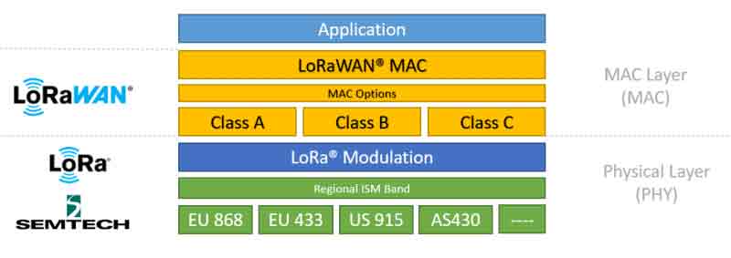
- LoRaWAN is an open protocol for low-power wide-area networks built on LoRa radio modulation technology. Designed to wirelessly connect battery-powered "things" to the Internet in regional, national, or global networks, and target critical Internet of Things (IoT) requirements such as two-way directional communication, end-to-end security, mobility, and localized services. The node wirelessly connects to the Internet with network access authentication, which is equivalent to establishing an encrypted communication channel between the node and the server. The LoRaWAN protocol level is shown in the figure below.
- The Class A/B/C node devices in the MAC layer cover all the application scenarios of the Internet of Things. The difference among them is that the time slots for nodes to send and receive are different.
- EU868 and AS430 in the Modulation layer show that frequency band parameters are different in different countries. Please click the reference link for regional parameters.
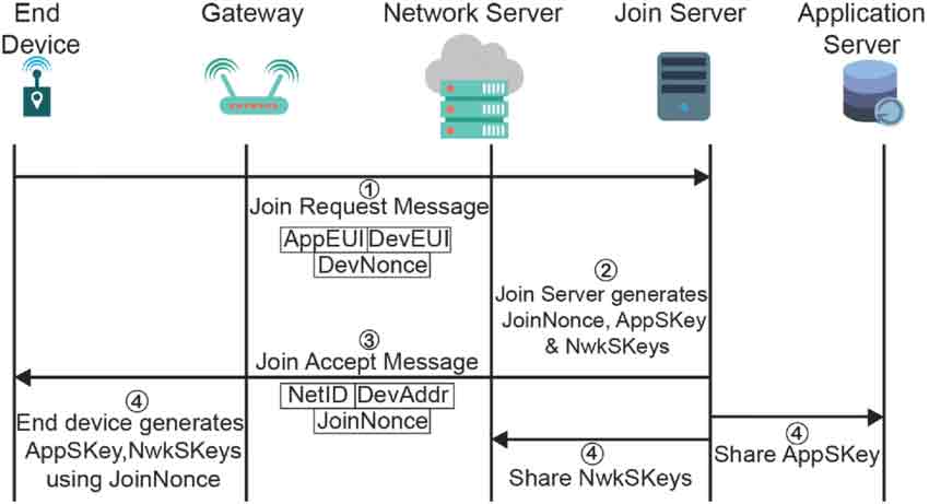
- To achieve LoRaWAN network coverage in cities or other areas, it needs to be composed of four parts: node (LoRa node radio frequency chip), gateway (or base station, LoRa gateway radio frequency chip), server, and cloud, as shown in the following figure.
- The DEVICE (node device) needs to initiate a network access request packet to the GATEWAY (gateway) and then to the server. After the authentication is passed, it can send and receive application data with the server normally.
- GATEWAY (gateway) can communicate with the server through a wired network, 3/4/5G wireless network
- The main operators on the server side are TTN, etc. For building cloud services by yourself, please refer to lorawan-stack, chirpstack

- There are two methods for Raspberry Pico and Pico-LoRa-SX1262 to connect to the network via LoRaWAN: OTAA (Over-The-Air-Activation) and ABP (Activation By Personalization). Here we use OTAA, as shown below. Also, you can refer to link 1, link 2 and source code.
- Step 1: Please send the "Join-Request" message to the network to join, and note that the join process is always initiated by the end device. The join-Request message can be transmitted at any rate and in one of the region-specific join channels. For example: in Europe, the end device can send the join-Request message at 868.10 MHz, 868.30MHz, or 838.50MHz. Also, the message can be sent to the network server by one or more gateway. In addition, you need to pay attention to choosing the applicable frequency band according to the local radio management regulations. You can refer to link and LoRa Alliance for the frequency distribution table. The Join-Request message is combined by the following fields. AppEUI and DevEUI are generated by registration on the server.
- AppEUI: A 64-bit globally unique application identifier in the IEEE EUI64 address space that uniquely identifies an entity capable of processing Join-Request frames.
- DevEUI: A 64-bit globally unique device identifier that uniquely identifies an end device in the IEEE EUI64 address space.
- DevNonce: A unique random 2-byte value generated by the end device. The web server uses each end device's DevNonce to keep track of their join requests. If the end device sends a join request with the previously used DevNonce (this case is called a replay attack), the network server will reject the join request and will not allow the end device to register with the network.
- Step 2: The web server handles the Join-Request-Message. If the end device is allowed to join the network, the web server will generate two session keys (NwkSKey and AppSKey) and the Join-accept message. The Join-accept message itself is then encrypted using AppKey. The web server uses AES decryption operation in ECB mode to encrypt Join-accept messages.
- Step 3: The network server sends the encrypted Join-accept message back to the end device as a normal downlink.
- Step 4: The end device uses AES to decrypt Join-Accept. And uses AppKey and AppNonce to generate two session keys (NwkSKey and AppSKey) for subsequent communication with the Networking server. The Network Server also saves kSKey, Join server distributes AppSKey to the Application Server.
- Step 1: Please send the "Join-Request" message to the network to join, and note that the join process is always initiated by the end device. The join-Request message can be transmitted at any rate and in one of the region-specific join channels. For example: in Europe, the end device can send the join-Request message at 868.10 MHz, 868.30MHz, or 838.50MHz. Also, the message can be sent to the network server by one or more gateway. In addition, you need to pay attention to choosing the applicable frequency band according to the local radio management regulations. You can refer to link and LoRa Alliance for the frequency distribution table. The Join-Request message is combined by the following fields. AppEUI and DevEUI are generated by registration on the server.
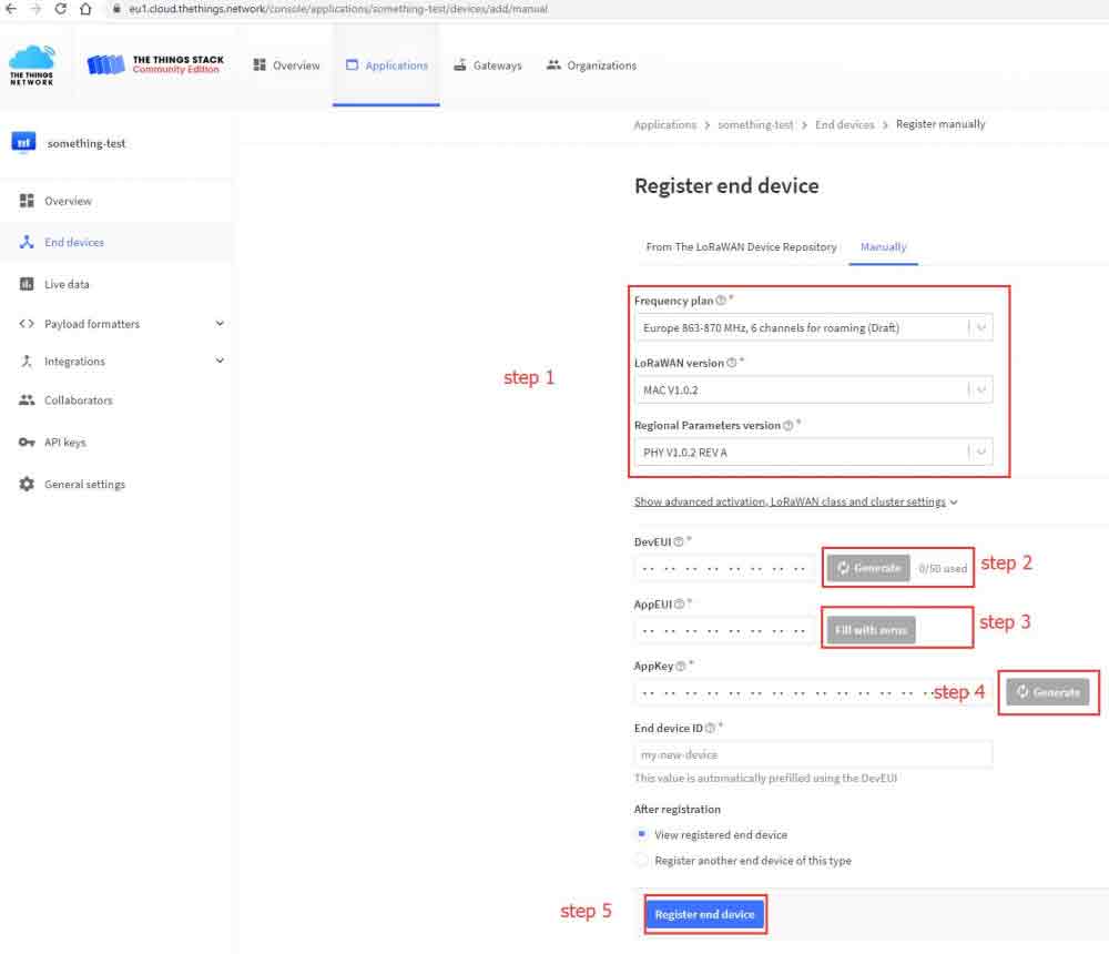
- The DevEUI and AppEUI parameters used as terminal devices to access the Internet need to be registered and generated by the server. The specific process is as follows.
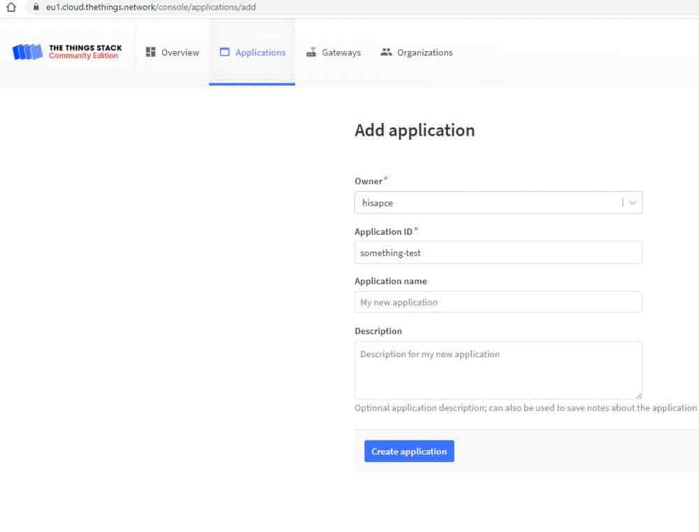
- Register an account in TTS and log in. Create an Application.
- Add an End Device

- Configure the End Device as in the picture. Please save the DevEUI and the AppKey for further use.
Application
LoRa devices and networks such as LoRaWAN enable smart IoT applications to help solve the planet's formidable challenges in energy management, natural resource reduction, pollution control, infrastructure efficiency, disaster prevention, and more. Semtech's LoRa devices have achieved hundreds of successful use cases in smart cities, homes and buildings, communities, metrology, supply chain, and logistics, agriculture, and more. LoRa networks have covered hundreds of millions of devices in more than 100 countries and are committed to a smarter planet.
Environment Building
- We use VScode(Cmake) to compile the environment on Windows 10 in this tutorial, and you can click to download the related IDE, install, and then open.
- Please refer to Pico Documentation and one-click installer for VScode(Cmake) compilation environment and its installation.

- After installing the RP2040 development environment with one click, open the terminal in the Windows Start menu directory, enter "code" to launch the VSCode compilation environment, and use VSCode to open the sample demo folder.
- Click the gear-shaped "Build" button in the toolbar below, pop up the compilation tool options tab, and select the GCC 10.3.1 arm-none-eabi compilation toolchain to compile the code.
Demo Analysis
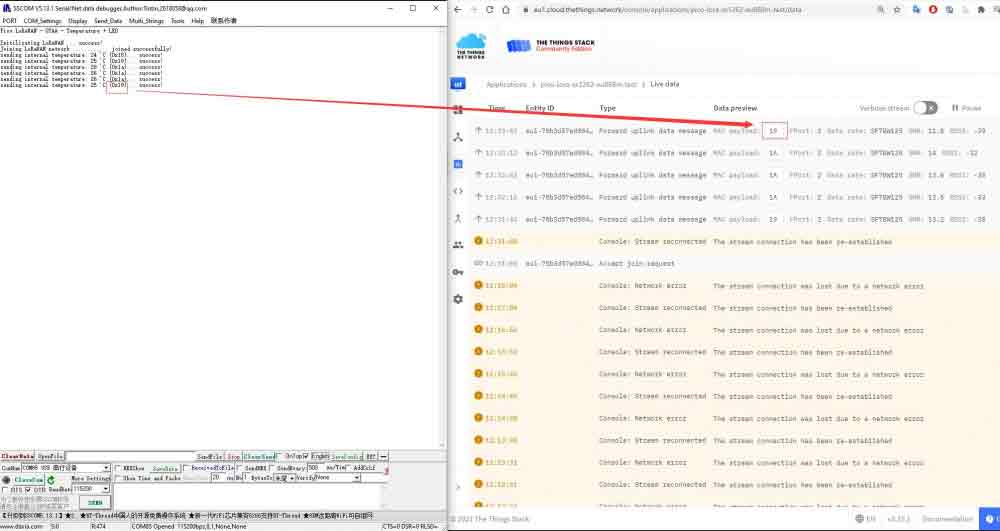
- In demo "RP2040-LoRa-code", "otaa_temperature_led" is for connecting the TTN cloud platform and transmitting the message, which requires a LoRaWAN gateway. Before compiling, you need to input the DevEUI and AppKey values that users apply in the cloud platform in the "config.h" text.
- If the environment settings are correct, click the Build button of VScode to wait for the compilation to end, download the compiled file to the RP2040-LoRa that enters the Boot mode (Press and hold the BOOT button to connect Type-C USB.), and open the serial port to view the log information.
- The ping-pong example requires two sets of RP2040-LoRa-HF-Kit for testing communication. After downloading the example, both modules will continuously send the "Ping" string message. Upon receiving the "Ping" message, one of them will reply with the "Pong" string.
- Radio.SetTxConfig() function is used to set the LoRa mode, including but not limited to bandwidth, spreading factor, coding rate, the length of the leading code, and other information, Radio.SetRxConfig() is used to set the information of the receiving mode, the built-in LoRa chip transmitting and receiving is a half-duplex state, at the same time can only be in send or receive mode.
    Radio.SetTxConfig( MODEM_LORA, TX_OUTPUT_POWER, 0, LORA_BANDWIDTH,
                                   LORA_SPREADING_FACTOR, LORA_CODINGRATE,
                                   LORA_PREAMBLE_LENGTH, LORA_FIX_LENGTH_PAYLOAD_ON,
                                   true, 0, 0, LORA_IQ_INVERSION_ON, 3000 );

    Radio.SetRxConfig( MODEM_LORA, LORA_BANDWIDTH, LORA_SPREADING_FACTOR,
                                   LORA_CODINGRATE, 0, LORA_PREAMBLE_LENGTH,
                                   LORA_SYMBOL_TIMEOUT, LORA_FIX_LENGTH_PAYLOAD_ON,
                                   0, true, 0, 0, LORA_IQ_INVERSION_ON, true );

    Radio.SetMaxPayloadLength( MODEM_LORA, BUFFER_SIZE );
- main() function uses the variable to label LoRa as Master by default, send "Ping", it enters the RX mode, waiting for "Pong" response. If the RX mode is timeout, you can send "Ping" again. If it receives a "Ping", it can be labeled as "Pong". Then, these two modules continuously transmit and receive like "Pingpong", and the onboard LED blinks when receiving the message.
while( 1 )
{
    switch( State )
    {
        case RX:
        case TX:
        case RX_TIMEOUT:
        case RX_ERROR:
        case TX_TIMEOUT:
        case LOWPOWER:
        default:
    }
    BoardLowPowerHandler( );
    // Process Radio IRQ
    if( Radio.IrqProcess != NULL )
    {
        Radio.IrqProcess( );
    }

}
Other Messages
- With the pico-lorawan foundation, this demo also includes support for the RP2040-LoRa module based on the Semtech SX1262.
- For LoRaWAN protocol, you can refer to this link.
- If you want to establish a cloud server by yourself, you can refer to lorawan-stack and chrpstack.
Pico Getting Started
Introduction
MicroPython Series
Install Thonny IDE
In order to facilitate the development of Pico/Pico2 boards using MicroPython on a computer, it is recommended to download the Thonny IDE
- Download Thonny IDE and follow the steps to install, the installation packages are all Windows versions, please refer to Thonny's official website for other versions
- After installation, the language and motherboard environment need to be configured for the first use. Since we are using Pico/Pico2, pay attention to selecting the Raspberry Pi option for the motherboard environment
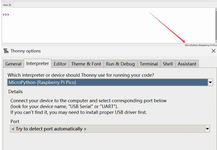
- Configure MicroPython environment and choose Pico/Pico2 port
- Connect Pico/Pico2 to your computer first, and in the lower right corner of Thonny left-click on the configuration environment option --> select Configture interpreter
- In the pop-up window, select MicroPython (Raspberry Pi Pico), and choose the corresponding port
Flash Firmware
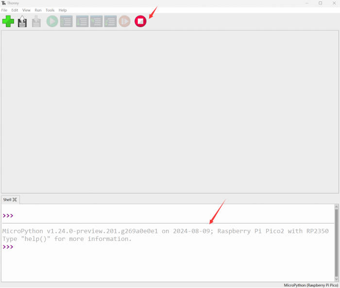
- Click OK to return to the Thonny main interface, download the corresponding firmware library and burn it to the device, and then click the Stop button to display the current environment in the Shell window
- Note: Flashing the Pico2 firmware provided by Micropython may cause the device to be unrecognized, please use the firmware below or in the package
- How to download the firmware library for Pico/Pico2 in windows: After holding down the BOOT button and connecting to the computer, release the BOOT button, a removable disk will appear on the computer, copy the firmware library into it
- How to download the firmware library for RP2040/RP2350 in windows: After connecting to the computer, press the BOOT key and the RESET key at the same time, release the RESET key first and then release the BOOT key, a removable disk will appear on the computer, copy the firmware library into it (you can also use the Pico/Pico2 method)
MicroPython Series
【MicroPython】 machine.Pin class function details
【MicroPython】machine.PWM class function details
【MicroPython】machine.ADC class function details
【MicroPython】machine.UART class function details
【MicroPython】machine.I2C class function details
【MicroPython】machine.SPI class function details
【MicroPython】rp2.StateMachine class function details
C/C++ Series
For C/C++, it is recommended to use Pico VS Code for development. This is a Microsoft Visual Studio Code extension designed to make it easier for you to create, develop, and debug projects for the Raspberry Pi Pico series development boards. No matter if you are a beginner or an experienced professional, this tool can assist you in developing Pico with confidence and ease. Here's how to install and use the extension.
- Official website tutorial: https://www.raspberrypi.com/news/pico-vscode-extension/
- This tutorial is suitable for Raspberry Pi Pico, Pico2 and the RP2040 and RP2350 series development boards developed by Waveshare
- The development environment defaults to Windows11. For other environments, please refer to the official tutorial for installation
Install VSCode
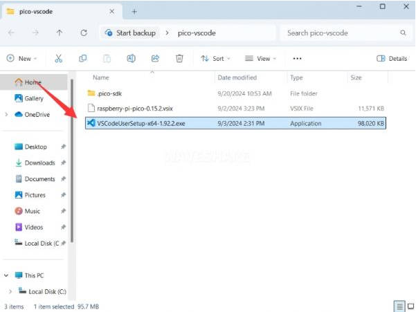
- First, click to download pico-vscode package, unzip and open the package, double-click to install VSCode
Note: If vscode is installed, check if the version is v1.87.0 or later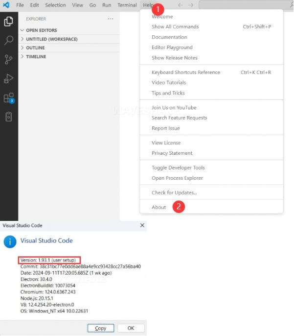
Install Extension
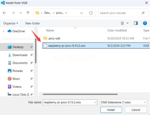
- Click Extensions and select Install from VSIX
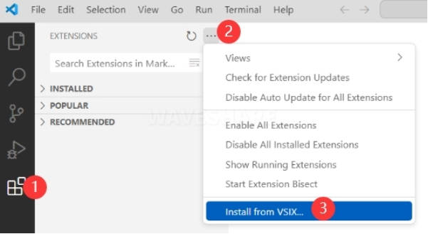
- Select the package with the vsix suffix and click Install
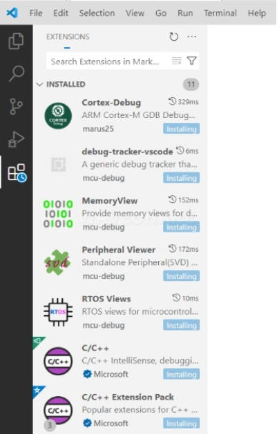
- Then vscode will automatically install raspberry-pi-pico and its dependency extensions, you can click Refresh to check the installation progress
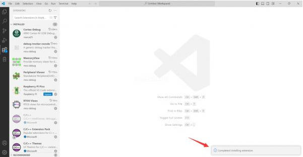
- The text in the right lower corner shows that the installation is complete. Close VSCode
Configure Extension
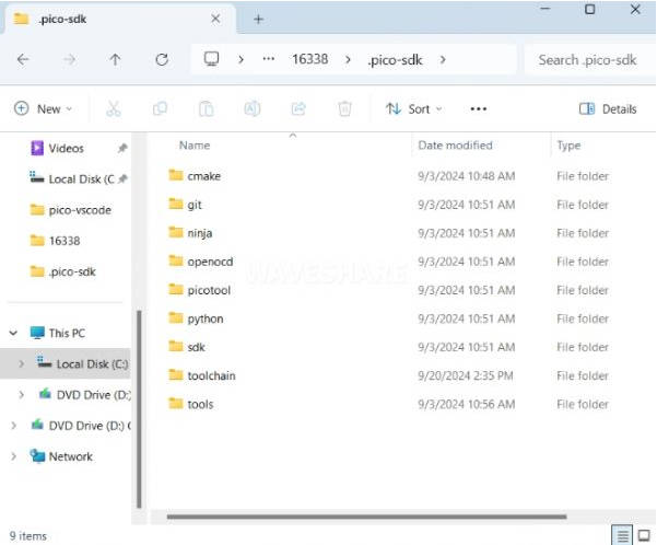
- Open directory C:\Users\username and copy the entire .pico-sdk to that directory
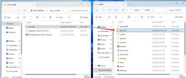
- The Copy is completed
- Open vscode and configure the paths for the Raspberry Pi Pico extensions
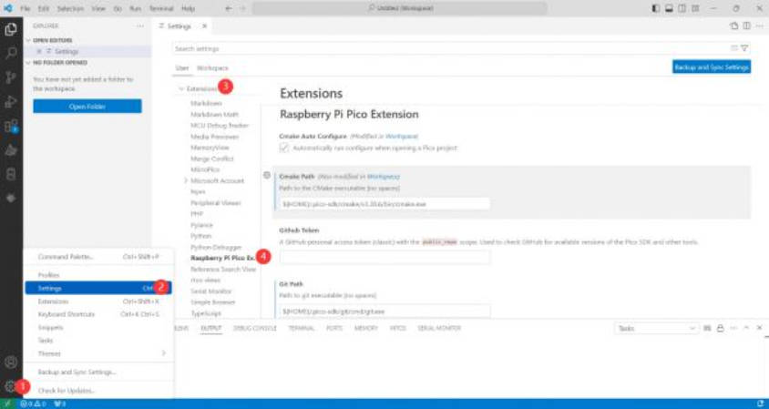
The configuration is as follows:Cmake Path: ${HOME}/.pico-sdk/cmake/v3.28.6/bin/cmake.exe Git Path: ${HOME}/.pico-sdk/git/cmd/git.exe Ninja Path: ${HOME}/.pico-sdk/ninja/v1.12.1/ninja.exe Python3 Path: ${HOME}/.pico-sdk/python/3.12.1/python.exe
New Project
- The configuration is complete, create a new project, enter the project name, select the path, and click Create to create the project
To test the official example, you can click on the Example next to the project name to select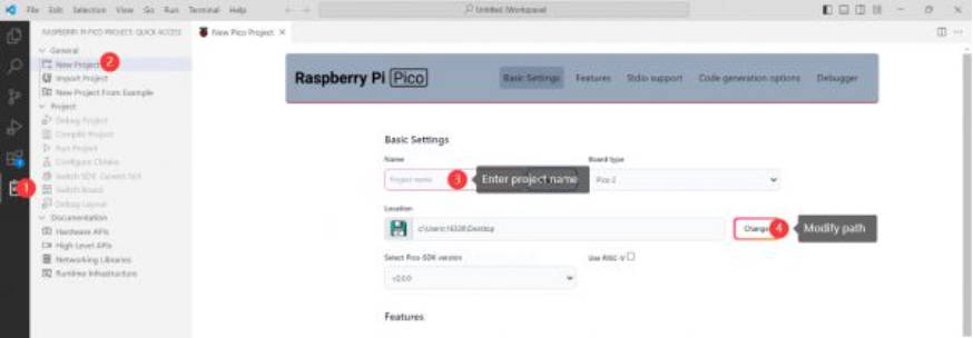
- The project is created successfully
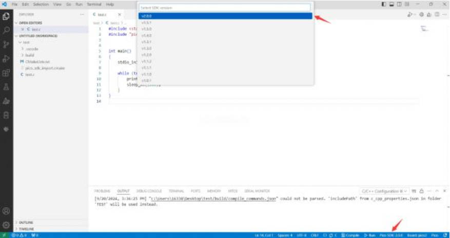
- Select the SDK version
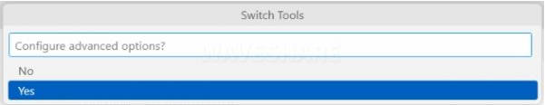
- Select Yes for advanced configuration
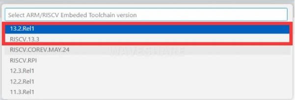
- Choose the cross-compilation chain, 13.2.Rel1 is applicable for ARM cores, RISCV.13.3 is applicable for RISCV cores. You can select either based on your requirements
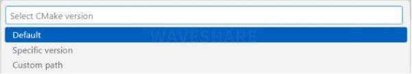
- Select default for CMake version (the path configured earlier)
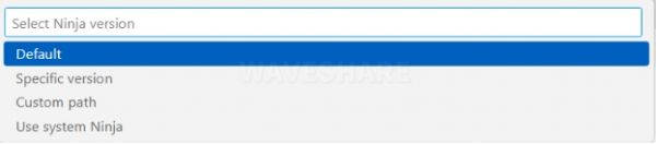
- Select default for Ninjaversion
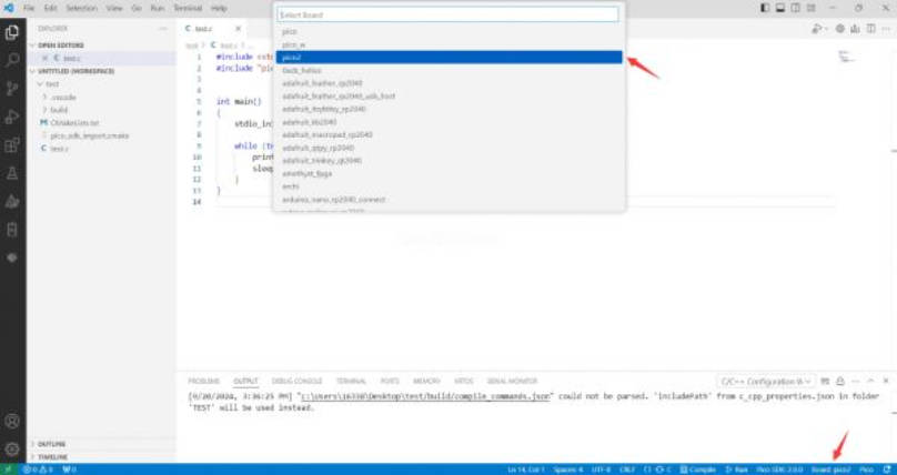
- Select the development board
- Click Complie to compile
- The uf2 format file is successfully compiled
Import Project
- The Cmake file of the imported project cannot have Chinese (including comments), otherwise the import may fail
- To import your own project, you need to add a line of code to the Cmake file to switch between pico and pico2 normally, otherwise even if pico2 is selected, the compiled firmware will still be suitable for pico
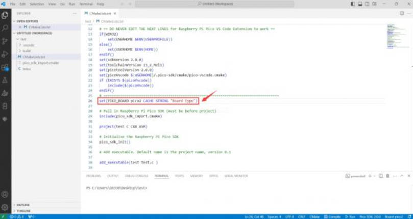
set(PICO_BOARD pico CACHE STRING "Board type")
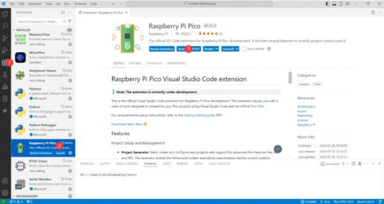
Update Extension
- The extension version in the offline package is 0.15.2, and you can also choose to update to the latest version after the installation is complete
Arduino IDE Series
Install Arduino IDE
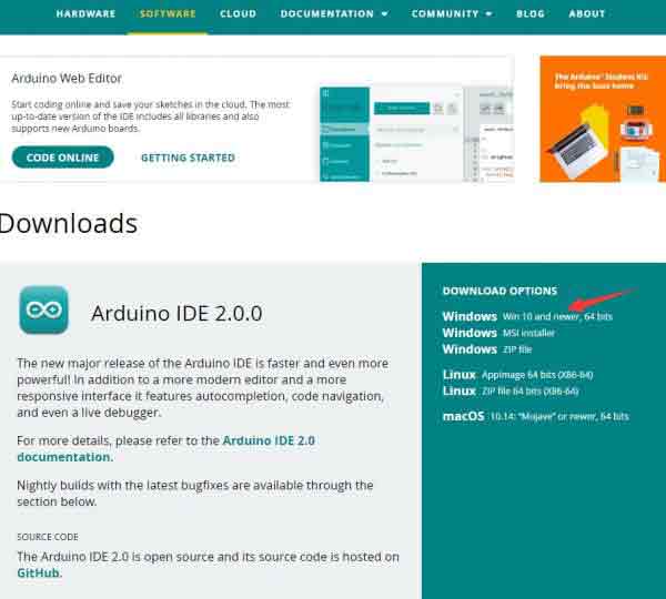
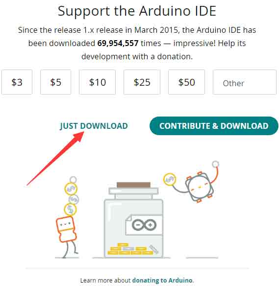
- First, go to Arduino official website to download the installation package of the Arduino IDE.
- Here, you can select Just Download.
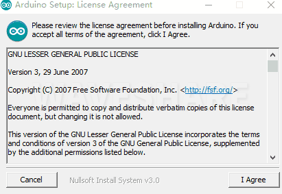
- Once the download is complete, click Install.
Notice: During the installation process, it will prompt you to install the driver, just click Install
600px
Arduino IDE Interface
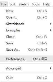
- After the first installation, when you open the Arduino IDE, it will be in English. You can switch to other languages in File --> Preferences, or continue using the English interface.
- In the Language field, select the language you want to switch to, and click OK.
Install Arduino-Pico Core in the Arduino IDE
- Open the Arduino IDE, click on the file in the top left corner, and select Preferences
- Add the following link to the attached board manager URL, and then click OK
https://github.com/earlephilhower/arduino-pico/releases/download/4.0.2/package_rp2040_index.json

Note: If you already have an ESP32 board URL, you can use a comma to separate the URLs as follows:https://dl.espressif.com/dl/package_esp32_index.json,https://github.com/earlephilhower/arduino-pico/releases/download/4.0.2/package_rp2040_index.json
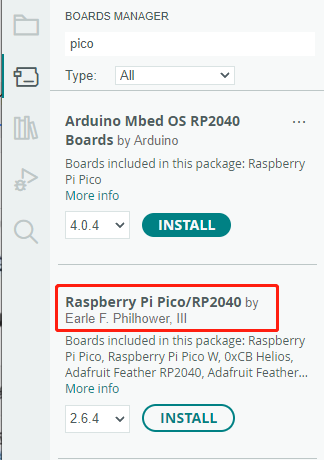
- Click Tools > Development Board > Board Manager > Search pico, as my computer has already been installed, it shows that it is installed

Upload Demo at the First Time
- Press and hold the BOOTSET button on the Pico board, connect the pico to the USB port of the computer via the Micro USB cable, and release the button after the computer recognizes a removable hard disk (RPI-RP2).
- Download the program and open D1-LED.ino under the arduino\PWM\D1-LED path
- Click Tools --> Port, remember the existing COM, do not click this COM (the COM displayed is different on different computers, remember the COM on your own computer)

- Connect the driver board to the computer using a USB cable. Then, go to Tools > Port. For the first connection, select uf2 Board. After uploading, when you connect again, an additional COM port will appear

- Click Tools > Development Board > Raspberry Pi Pico > Raspberry Pi Pico or Raspberry Pi Pico 2

- After setting it up, click the right arrow to upload the program
- If issues arise during this period, and if you need to reinstall or update the Arduino IDE version, it is necessary to uninstall the Arduino IDE completely. After uninstalling the software, you need to manually delete all contents within the C:\Users\[name]\AppData\Local\Arduino15 folder (you need to show hidden files to see this folder). Then, proceed with a fresh installation.
Open Source Demos
MircoPython video demo (github)
MicroPython firmware/Blink demos (C)
Raspberry Pi official C/C++ demo (github)
Raspberry Pi official micropython demo (github)
Arduino official C/C++ demo (github)
Resource
Document
Demo
Datasheet
Development Software
- Zimo221.7z
- Image2Lcd.7z
- Font Library Tutorial
- Image Extraction Tutorial
- Thonny Python IDE (Windows V3.3.3)
Support
Monday-Friday (9:30-6:30) Saturday (9:30-5:30)
Email: services01@spotpear.com
[Tutorial Navigation]
- Overview
- Introduction
- Features
- Specification
- Hardware Description
- LoRa & LoRaWAN
- Environment Building
- Demo Analysis
- Other Messages
- Pico Getting Started
- Resource
- Support