


- sales/support
Google Chat:---
- sales
+86-0755-88291180
- sales01
sales@spotpear.com
- sales02
dragon_manager@163.com
- support
tech-support@spotpear.com
- CEO-Complaints
zhoujie@spotpear.com
- Only Tech-Support
WhatsApp:13246739196
- Purchase/Shipping/Refund
WhatsApp:13424403025
- HOME
- >
- ARTICLES
- >
- Common Moudle
- >
- ESP
Thermal-45 Camera ESP32 Module User Guide
Introduction
This product is a wireless IR thermal imaging camera based on the ESP32-S3-WROOM-1 chip, adopts the hybrid technology of microbolometer and thermopile pixel, features 80x62 array pixels. It will detect the IR radiation energy distribution of objects in the field of view of the lens in real time, and generate temperature distribution maps and thermal imaging images of the surface of the objects through quantization processing. In addition, it integrates a recharge and discharge circuit, with onboard Lithium battery header for flexible power supply.
Features
- Equipped with ESP32-S3-WROOM-1 module and Xtensa 32-bit LX7 dual-core processor, up to 240MHz main frequency, offering powerful data processing capabilities
- Onboard antenna, supporting 2.4 GHz WIFI (802.11 b/g/n) and Bluetooth 5 (LE) dual-mode communication
- Built in 512KB SRAM and 384KB ROM, with onboard 8MB PSRAM and an external 16MB Flash
- Type-C connector, enhancing device compatibility and user convenience
- Onboard RGB LED indicator, real-time display of module operation status, convenient for equipment monitoring and maintenance
- Onboard 3.7V MX1.25 Lithium battery recharge / discharge header for flexible power supply solution, extending device operation time
- Onboard 2 × 10 solder pads, including 14 × GPIO, 1 × I2C, and 1 × UART, for external device expansion
- Compact size design, more space-saving, making it ideal for embedded applications
Specifications
- Operating voltage: 5V
- Operating voltage: 127mA@5V
- Wavelength range: 8~14μm
- Field of View (FOV):
- 56°(D) × 45°(H) × 34°(V) (Baisc version)
- 122°(D) × 90°(H) × 67°(V) (Wide angle version)
- Operating temperature: -40℃~85℃
- Target Temperature: -40℃~400℃
- Detection accuracy: ±2℃
- Refresh Rate: 25 FPS(Max)
- Due to the influence of WiFi signals, there may be errors in the actual frame rate, subject to the usage environment.
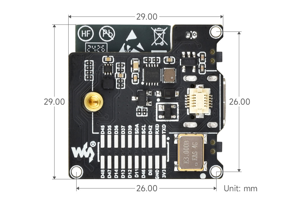
- Dimensions: 29.0 × 29.0(mm)
- Noise Equivalent Temperature Difference (NETD): 125mK
Pinout Definition
Reserved GPIO
The module leads out the idle pins of ESP32 S3, making it convenient for users to solder the pins themselves. If additional welding is needed, please make sure to remove the lens module first. You can use the 2x10 patch pin header with pitch of 1.27mm.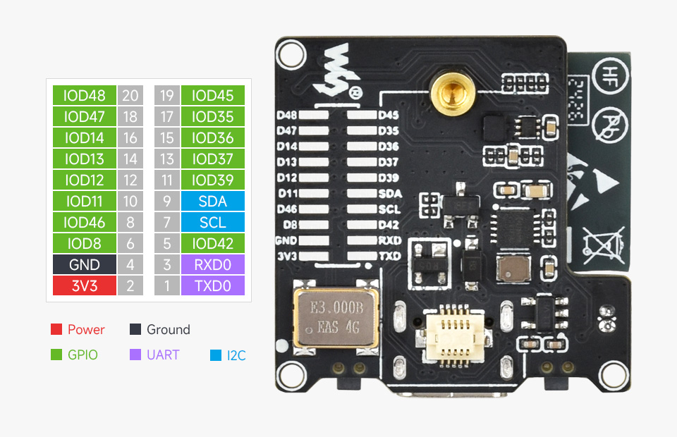
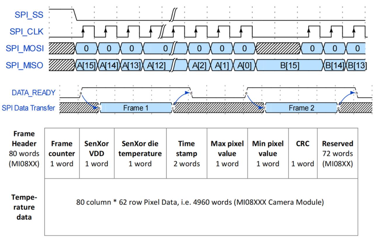
SPI Bus
The ESP32 S3 module controls the thermal imaging module via SPI
- The SPI read timing diagram of the module is shown in the figure below. For more details, please refer to the datasheet
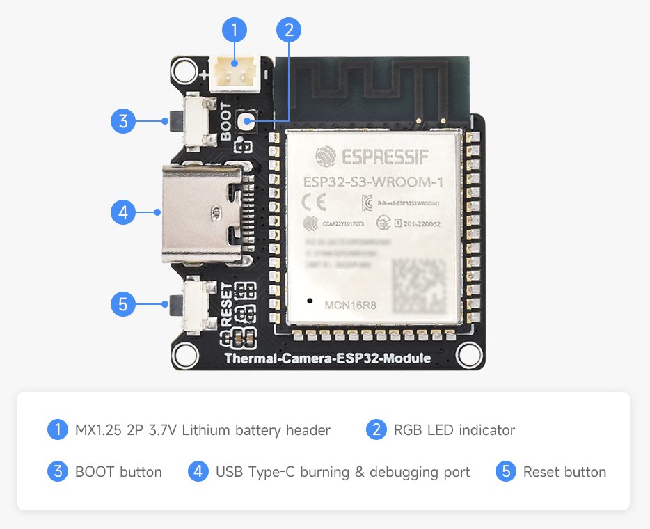
Hardware Interfaces
Dimensions
Temperature Measurement Principle
What is infrared temperature measurement? (Refer to OPTRIS)
In the field of measurement, "temperature" is one of the most commonly used physical parameters after "time". Based on the principles of Planck's and Boltzmann's radiation laws, an infrared thermometer measures the temperature of an object by absorbing the infrared radiation emitted by the object. So, how does non-contact temperature measurement work?
Any object with a temperature above absolute zero (0 K or -273.15 °C) emits electromagnetic radiation from the surface, and the radiation is proportional to the object's inherent temperature. This radiation includes infrared radiation used to achieve temperature measurement. When this radiation penetrates the atmosphere, it can be concentrated on the detector with the help of a special lens. The detector then generates an electrical signal proportional to this radiation. This signal is amplified and converted into an output signal proportional to the temperature of the object by undergoing continuous digital signal processing. In this way, the measured value of the temperature will be displayed on the display, or output as a signal.
In the application of radiation for temperature measurement, the emissivity ε (Epsilon) plays a crucial role. It shows the relationship between the radiation values of actual objects and those of a black body. The emissivity of a black body is 1 (maximum value). However, there are not many objects that can meet the ideal condition of a black body. When calibrating the sensor, the contact surface of the radiator (including the recommended wavelength: 0.99) is generally used.
In terms of their wavelength, many objects usually have a constant emissivity, but their radiation capacity is much inferior to that of a black body, they are called gray bodies. If the emissivity of an object depends on its temperature and wavelength (e.g., metal), it is called a selective radiator. In both cases, the missing radiation part is explicitly supplemented by the radiation rate. When using selective radiators, it is important to keep in mind the wavelength being measured (for metals, short wavelengths are chosen).
In addition to the radiation emitted from the surface of the object, the infrared sensor can also receive reflected radiation from the surrounding environment and perhaps penetrating infrared radiation from the object being measured.
Measurement Distance
- Based on the 175cm mannequin and the test distance is about 12m, the contours of the human body will not be distinguished
Measurement Accuracy
- When the target object exceeds the FOV of the module by 25% or more, the relative humidity should be below 95%, and there should be no condensation vapor or moisture on the lens
| Operating temperature °C | Target temperature °C | Maximum deviation °C | |
| Full frame accuracy | 30.0 | 32.0-40.0 | ±1.0 (center 32x24),±1.2 (entire) |
| 30.0 | 10-32.0,40.0-70.0 | ±1.5 (entire) | |
| 30.0 | <10.0,>70.0 | ±2.0 (entire FPA), or 5% | |
| Single pixel | 30.0 | 32.0-40.0 | ±0.5 (center 32x24),±0.7 (entire) |
| 30.0 | 10-32.0,40.0-70.0 | ±1.0 (entire) | |
| 30.0 | 32.0-40.0 | ±2.5 (entire), or 5% | |
| Temperature stability | 30.0 | 32.0-40.0 | -0.21℃/℃ |
| Power stability | 30.0 | - | ±1.0 ℃ / 100 mA |
Usage Instructions
We provide source code and factory firmware. The module is tested and pre-programmed with the factory firmware before shipment. Users can configure WiFi parameters and perform tests using a Bluetooth App.
Bluetooth APP Configuration Intructions
The program supports setting WiFi parameters through Bluetooth, making it convenient for users to switch WiFi environments in actual use without the need for additional program compilation and download. The app can only support Android phones.
- Download Bluetooth APP, unzip the apk file, and copy the file to your Android phone to install it
- After installation, it will prompt for app permission authorization. Please set up the modules according to the prompts
- Click Refresh to scan for nearby Bluetooth devices The default device name is "ESP32S3 BlueFi", click the device to enter the configuration
- Users can modify the WIFI to be connected to the device according to the page information, and then click Apply Changes to configure the module
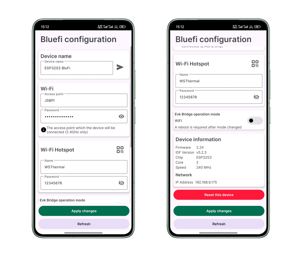
Host Computer Preview
After the module is successfully configured, users can debug the output through the serial port, or directly check the IP of the device on the Bluetooth APP page. In AP mode, the module's IP defaults to 192. 168.4.1 with port number 3333
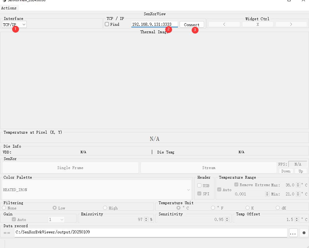
- STA Mode Test
- The computer needs to be connected to the same WiFi network as the module.
- Download the software and open the host computer for preview test.
- Select TCP/IP mode for interface
- Enter the module IP in the IP input box for preview, for example, 192.168.9.131:3333
- Click the Connect button to connect the module and preview it
- AP Mode Test
- The module supports hotspot mode. The default hotspot name is WSThermal and the password is 12345678
- The computer scans and connects to the WSThermal hotspot. As the hotspot does not support networking, some computers may automatically disconnect after being connected and need to be reconnected
- After successful connection, use the upper computer software to connect the 192.168.4.1:3333 module for preview
Note: After obtaining thermal imaging images using AP mode, you need to press the Reset button to restart the module before switching back to STA mode.
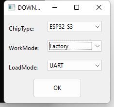
Factory Firmware Flashing Instructions
In order to facilitate users in resetting modules and testing, we provide factory firmware and flashing tools to facilitate users to re-flash factory firmware for testing.
- Download sample programs and firmware flashing programs.
- Connect the module to the PC via a USB cable.
- Open the flashing software. Select the bin file as shown in the diagram and click Start to flash
- Actually, the address is set to 0
- You can view the device manager of the computer to obtain the COM port
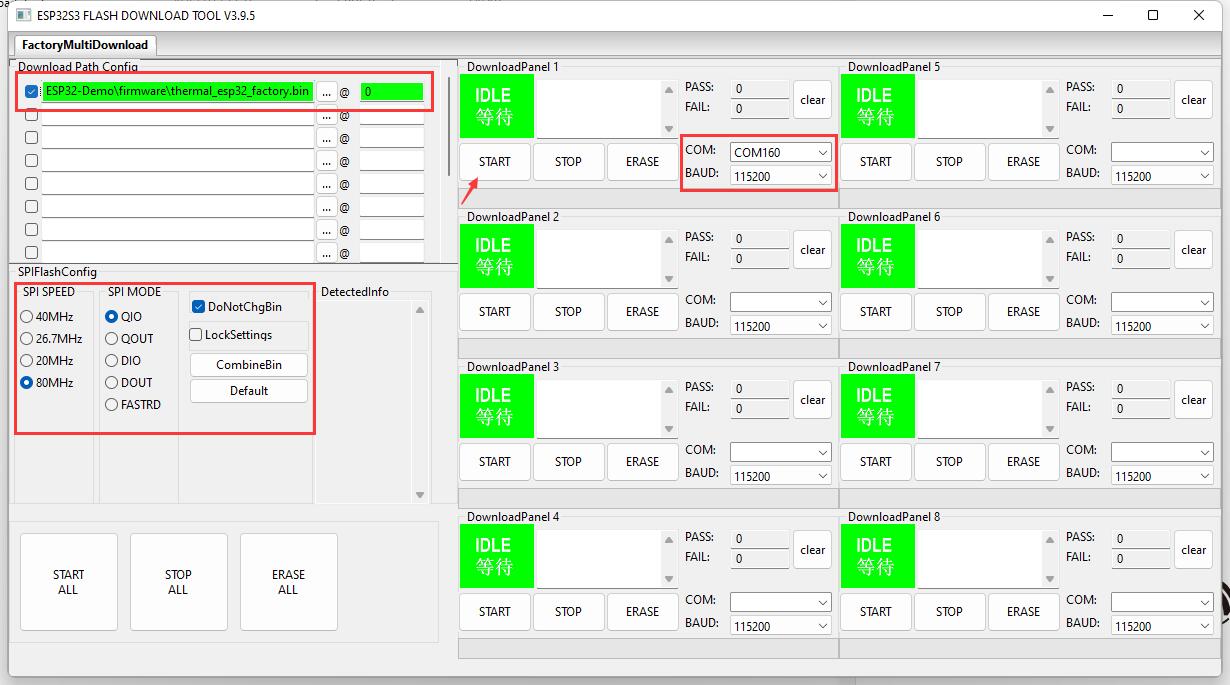
- After successful flashing, you can press the Reset button to power on the module again and test it
VS Code Demo Usage
The demos we provide are based on VS Code and ESP-IDF. If the user has other development environment requirements, they need to refer to the demo and configure it themselves.
Environment Setup
ESP-IDF environment setup, including the installation of Visual Studio and Espressif IDF plugins, as well as providing simple program compilation, download, and demo testing tutorials for first-time users to help them smoothly set up the environment and use it

- Install VS Code
- Open the download page of VScode official website, choose the corresponding system and system bit to download

- After running the installation package, the rest can be installed by default, but here for the subsequent experience, it is recommended to check boxes 1, 2, and 3
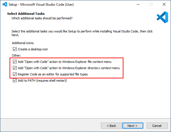
- After the first two items are enabled, you can open VSCode directly by right-clicking files or directories, which can improve the subsequent user experience.
- After the third item is enabled, you can select VSCode directly when you choose how to open it
- Install Espressif IDF Plugin
- It is generally recommended to use Install Online. If online installation fails due to network factor, use Install Offline
- The tutorial environment is 5.1.4, we need to download 5.3.2
- To install ESP IDF 5.3.2 development environment tutorial, see Install Espressif IDF Plugin
Program Compilation Download
The firmware source code is provided in the Resources section. Users who need it can download it and perform secondary development
- Choose File -> Open Folder, find the SENXORESP32S3 directory in the program and select to open
- After opening the folder, the software will automatically detect the program environment configuration
- After environmental adaptation, select to ESP-IDF v5.2.3 version SDK, and choose the corresponding COM port based on the interface of the Device Manager
- Select ESP32S3 board model
- Successfully configured, select Build Project to compile the program, and then click Flash Device to download the program to the development board
Resources
Demo
Software
Datasheets
FAQ
Support
Monday-Friday (9:30-6:30) Saturday (9:30-5:30)
Mobile: +86 13434470212
Email: services01@spotpear.com
