


- sales/support
Google Chat:---
- sales
+86-0755-88291180
- sales01
sales@spotpear.com
- sales02
dragon_manager@163.com
- support
tech-support@spotpear.com
- CEO-Complaints
zhoujie@spotpear.com
- Only Tech-Support
WhatsApp:13246739196
- Purchase/Shipping/Refund
WhatsApp:13424403025
Modbus-RTU-Relay-D Guide
Resource
Demo
Software
Overview
Electrical Safety Precautions
- This product should be operated and used by professional electricians or technical personnel. Please ensure electrical safety measures are in place, including protection against leakage and insulation.
- Before installing, maintaining, or replacing relay equipment, always turn off the power and unplug the plug.
- Do not attempt to dismantle relay equipment to avoid damaging the device or risking electric shock.
- Please properly install and place relay equipment. Avoid use in damp, overheated, or flammable environments to prevent accidents caused by improper installation or use.
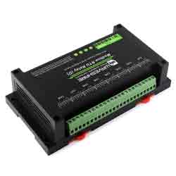
This is an industrial 8-ch relay module controlled via RS485 bus, with 8-ch digital input, utilizing Modbus RTU protocol. It features embedded protection circuits such as power isolation, magnetical isolation, TVS diode, etc. It also comes with an ABS enclosure. The Modbus RTU Relay (D) is very easy to use. Due to its fast communication, stability, reliability, and safety, it is an ideal choice for industrial control equipment and/or applications with high communication requirements.
Parameters
| Power Supply | 7~36V |
|---|---|
| Communication Interface | RS485 |
| Baudrate | 4800, 9600, 19200, 38400, 57600, 115200, 128000, 256000 |
| Default Communication Format | 9600, N, 8, 1 |
| Relay Channels | 8 Channels |
| Contact Form | 1NO, 1NC |
| Contact Load | ≤10A 250V AC or ≤10A 30V DC |
| Digital Input | 8DI, 5~36V, passive / active input (NPN or PNP), built-in bi-directional optocoupler isolation |
| Modbus Protocol | Standard Modbus RTU protocol |
| RS485 Address Setting | 1~255 |
| Indicator | STA: MCU indicator, keep flashing when MCU normally working TXD: TX indicator, lights up when sending data RXD: RX indicator, lights up when receiving data |
Primary Functions
Supports reading digital input by sending Modbus RTU protocol commands via RS485 for digital output control.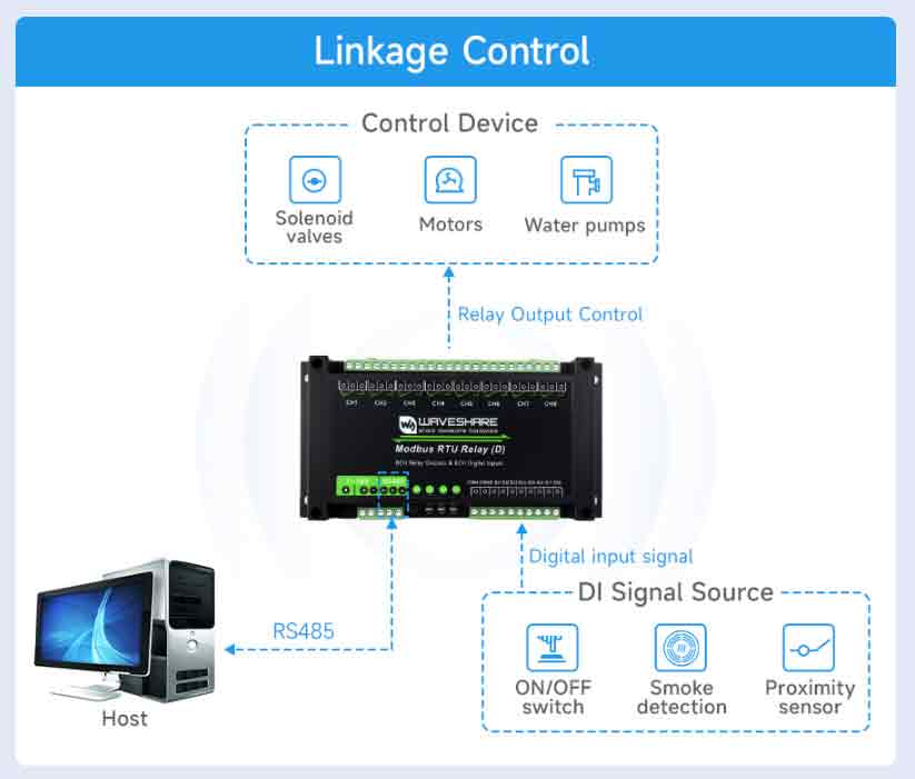
Wiring Description

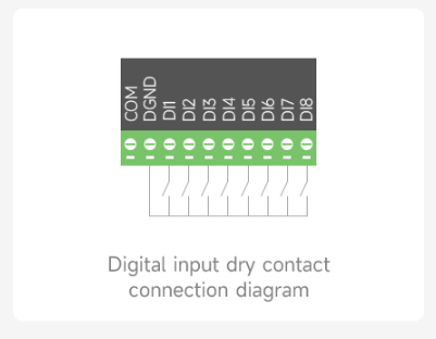
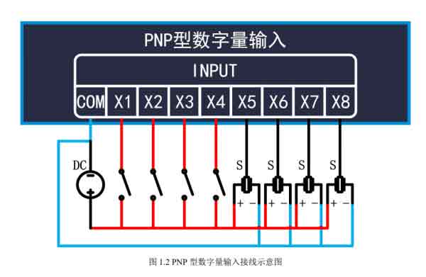
- DI1-DI8 is the 8-ch signal input terminal, and DGND is the ground signal. COM is the common terminal for the input signal, NC, or power supply positive or negative, can be directly from the power supply, and can also be connected to an independent power supply power supply.
- NC: dry contact passive input.
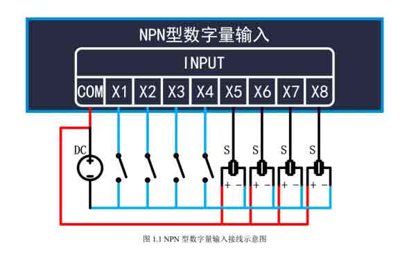
- Connect to the power supply positive: low active, NPN wet contact active input, voltage: 5V-30V DC.
- Connect to the power supply negative: high active, PNP wet contact active input.
Digital Input Wiring
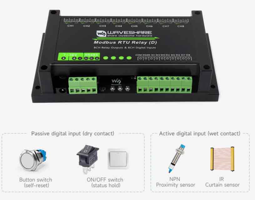
Passive Dry Contact Wiring
- Passive dry contact input:
Active Wet Contact Wiring
- Active wet contact NPN input
- Active wet contact PNP input
Relay Output Wiring
The device comes with a relay with a contact capacity of 10A 250V AC or 10A 30V DC, which allows direct control of household 220V AC equipment or DC equipment up to 30V.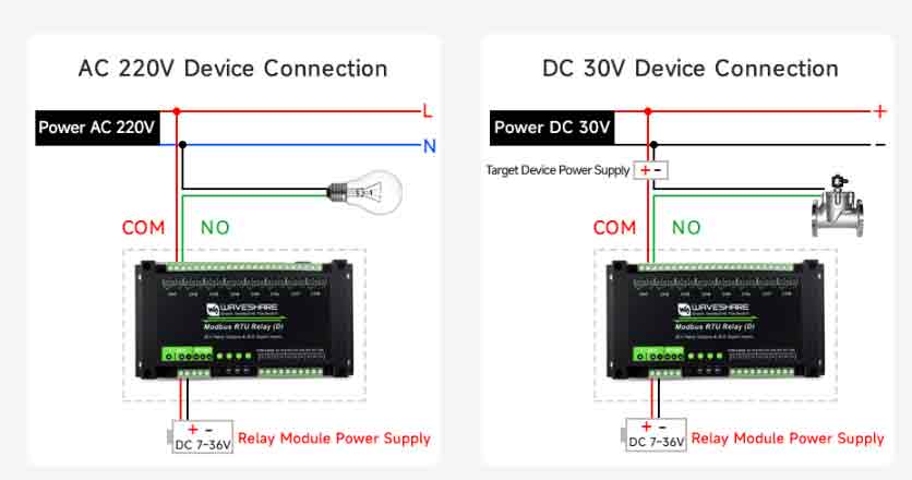
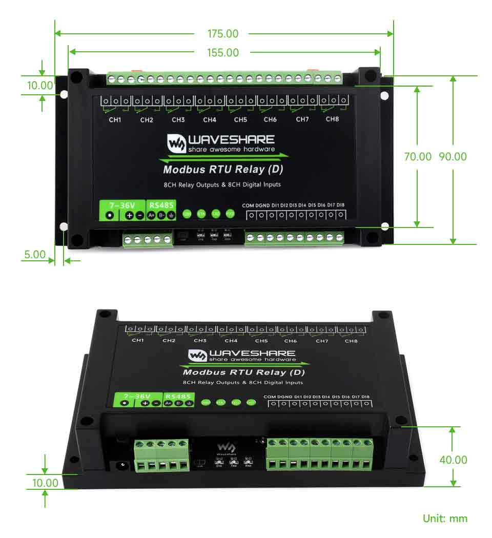
Dimensions
Hardware Test
RS485 Test
- Connect the USB TO 485 to the target board through wires, A-A and B-B as shown below:
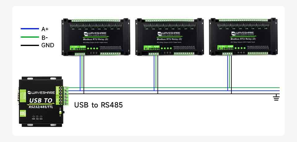
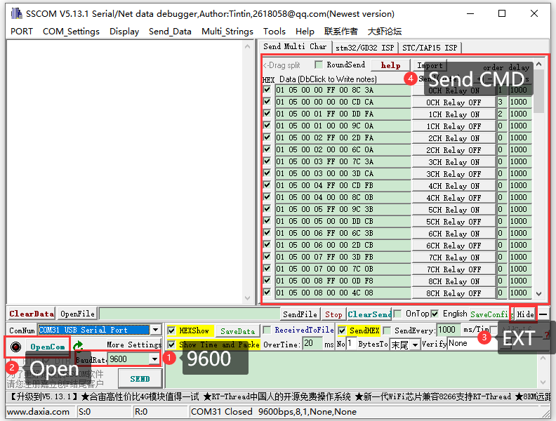
- Download SSCOM and open it on the computer, open the corresponding port number, and set the baud rate as 9600. Clicking on multiple strings will open multiple string-sending windows. Clicking on the corresponding function will send the corresponding command.
- If you need to send other commands then select HEX to send, plus check select ModbusCRC16 checksum, enter the first six bytes of the command, and click send then the CRC checksum will be added automatically.
- For detailed control commands, please see the development protocol.
Demo Test
Note: RS485 can not be directly connected to the serial port of the Raspberry Pi, otherwise it may burn the device, you need to add 485 level conversion, the Raspberry Pi is recommended to use with the RS485 CAN HAT module, NUCLEO-F103RB, and Arduino is recommended to use with the RS485 CAN Shield module!
Raspberry Pi
Open the Raspberry Pi terminal and input the following commands to enter the configuration interface.
sudo raspi-config
Select Interfacing Options -> Serial Port, select Yes to open the hardware serial port
And then reboot the Raspberry Pi:
sudo reboot
Insert the RS485 CAN HAT into the Raspberry Pi, and connect the Modbus RTU Relay module to the RS485 CAN HAT through A and B.
If you are using other 485 devices, you need to make sure A-A, B-B.
Run the following commands:
sudo apt-get install unzip
wget https://files.waveshare.com/wiki/Modbus-RTU-Relay-(D)/Modbus_RTU_Relay_D_Code.zip
unzip Modbus_RTU_Relay_D_Code.zip
cd Modbus_RTU_IO_Code/Python3
sudo python3 main.py
After the demo normally runs, each channel can be opened and closed in order, and the current input status is displayed.
STM32
The STM32 demo is based on the NUCLEO-F103RB and RS485 CAN Shield module.
Find the STM32 demo file directory and open the STM32 project. Please note that the keil5 software is installed before use, and download the demos to the development board.
After running normally, each channel can opened and closed in order. The serial port will output the commands to be sent and finally display the current input status.
Arduino
The Arduino demo is based on the UNO PLUS and RS485 CAN Shield module.
Use the Arduino IDE to open the demo, select the corresponding development board, and download the demos.
After running normally, each channel will open and close in order. The serial port will output the commands to be sent and finally display the current input status.
Development Protocol
Function Code Introduction
| Function Code | Description |
|---|---|
| 01 | Read output status |
| 02 | Read input status |
| 03 | Read save register |
| 05 | Write single relay |
| 06 | Set single register |
| 0F | Write multiple relays |
| 10 | Set multiple registers |
Register Address Introduction
| Address(HEX) | Address storage content | Register value | Permission | Modbus Function Code |
|---|---|---|---|---|
| 0x0000 …… 0x0007 | Channel 1~8 relay address | 0xFF00: relay on 0x0000: relay off 0x5500: relay toggle | Read/Write | 0x01, 0x05, 0x0F |
| 0x00FF | Control All Registers | 0xFF00: all relays on 0x0000: all relays off 0x5500: all relays toggles | Write | 0x05 |
| 0x0200 …… 0x0207 | Channel 1~8 relay flash on | Interval time: data*100ms Value: 0x0007, Interval time: 7*100MS = 700MS | Write | 0x05 |
| 0x0400 …… 0x0407 | Channel 1~8 relay flash off | Interval time: data*100ms Value: 0x0007, Interval time: 7*100MS = 700MS | Write | 0x05 |
| 1x0000 …… 1x0007 | Channel 1~8 input address | Indicates channel 0~8 input channel status | Read | 0x02 |
| 4x1000 …… 4x1007 | Channel 1~8 relay control mode | 0x0000~0x0002 control mode | Read/Write | 0x03, 0x06, 0x10 |
| 4x2000 | UART Parameters | The high eight bits indicate the parity mode: 0x00~0x02 The low eight bits indicate the baud rate mode: 0x00~0x07 | Write | 0x06 |
| 4x4000 | Device Address | Directly store Modbus address Device address: 0x0001-0x00FF | Read/Write | 0x03, 0x06 |
| 4x8000 | Software Version | Converting to decimal and then shifting the decimal point two places to the left will represent the software version 0x0064 = 100 = V1.00 | Read | 0x03 |
Single Relay Control
Send code: 01 05 00 00 FF 00 8C 3A
| Field | Description | Note |
|---|---|---|
| 01 | Device Address | 0x00 indicates the broadcast address, 0x01-0xFF indicates the device address |
| 05 | 05 Command | Relay control |
| 00 00 | Address | The register address of relays to be controlled, 0x0000 - 0x0008 |
| FF 00 | Command | 0xFF00: Relay on 0x0000: Relay off 0x5500: Relay toggle |
| 8C 3A | CRC16 | The CRC16 checksum of the first 6 bytes of data |
Receive code: 01 05 00 00 FF 00 8C 3A
| Field | Description | Note |
|---|---|---|
| 01 | Device Address | 0x00 indicates the broadcast address, 0x01-0xFF indicates the device address |
| 05 | 05 Command | Relay control |
| 00 00 | Address | The register address of relays to be controlled, 0x0000-0x0008 |
| FF 00 | Command | 0xFF00: Relay on 0x0000: Relay off 0x5500: Relay toggle |
| 8C 3A | CRC16 | The CRC16 checksum of the first 6 bytes of data |
For example:
[Address 1 device]:
Relay 0 on: 01 05 00 00 FF 00 8C 3A
Relay 0 off: 01 05 00 00 00 00 CD CA
Relay 1 on: 01 05 00 01 FF 00 DD FA
Relay 1 off: 01 05 00 01 00 00 9C 0A
Relay 2 on: 01 05 00 02 FF 00 2D FA
Relay 2 off: 01 05 00 02 00 00 6C 0A
Relay 3 on: 01 05 00 03 FF 00 7C 3A
Relay 3 off: 01 05 00 03 00 00 3D CA
Relay 0 toggle: 01 05 00 00 55 00 F2 9A
Relay 1 toggle: 01 05 00 01 55 00 A3 5A
Relay 2 toggle: 01 05 00 02 55 00 53 5A
Relay 3 toggle: 01 05 00 03 55 00 02 9A
Control All Relays
Send code: 01 05 00 FF FF 00 BC 0A
| Field | Description | Note |
|---|---|---|
| 01 | Device Address | 0x00 indicates the broadcast address, 0x01-0xFF indicates the device address |
| 05 | 05 Command | Relay control |
| 00 FF | Address | Fixed 0x00FF |
| FF 00 | Command | 0xFF00: Relay on 0x0000: Relay off 0x5500: Relay toggle |
| BC 0A | CRC16 | The CRC16 checksum of the first 6 bytes of data |
Receive code: 01 05 00 FF FF 00 BC 0A
| Field | Description | Note |
|---|---|---|
| 01 | Device Address | 0x00 indicates the broadcast address, 0x01-0xFF indicates the device address |
| 05 | 05 Command | Relay control |
| 00 FF | Address | Fixed 0x00FF |
| FF 00 | Command | 0xFF00: Relay on 0x0000: Relay off 0x5500: Relay toggle |
| BC 0A | CRC16 | The CRC16 checksum of the first 6 bytes of data |
For example:
[Address 1 device]:
All relays on: 01 05 00 FF FF 00 BC 0A
All relays off: 01 05 00 FF 00 00 FD FA
All relays toggle: 01 05 00 FF 55 00 C2 AA
Read Relay Status
Send code: 01 01 00 00 00 08 3D CC
| Field | Description | Note |
|---|---|---|
| 01 | Device Address | 0x00 indicates the broadcast address, 0x01-0xFF indicates the device address |
| 01 | 01 Command | Query relay status |
| 00 00 | Relay Start Address | Fixed 0x0000 |
| 00 08 | Relay Numbers | Fixed 0x0008 |
| 3D CC | CRC16 | The CRC16 checksum of the first 6 bytes of data |
Receive code: 01 01 01 00 51 88
| Field | Description | Note |
|---|---|---|
| 01 | Device Address | 0x00 indicates the broadcast address, 0x01-0xFF indicates the device address |
| 01 | 01 Command | Query relay status |
| 01 | Byte Numbers | Returns all bytes of the status message |
| 00 | Query Status | Received relay status Bit0: the first relay status; Bit1: the second relay status; Bit2: the third relay status; …… Bit7: the eighth relay status |
| 51 88 | CRC16 | The CRC16 checksum of the first 6 bytes of data |
For example:
[Address 1 device]:
Send: 01 01 00 00 00 08 3D CC
Receive: 01 01 01 00 51 88 //all relays off
Send: 01 01 00 00 00 08 3D CC
Receive: 01 01 01 01 90 48 //Relay 0 is on, the rest of the relays are off
Send: 01 01 00 00 00 08 3D CC
Receive: 01 01 01 41 91 B8 //Relay 0 and 6 are on, the rest of the relays are off
Write Relay Status
Send code: 01 0F 00 00 00 08 01 FF BE D5
| Field | Description | Note |
|---|---|---|
| 01 | Device Address | 0x00 indicates the broadcast address, 0x01-0xFF indicates the device address |
| 0F | 0F Command | Write relay status |
| 00 00 | Relay Start Address | Fixed 0x0000 |
| 00 08 | Relay Numbers | Fixed 0x0008 |
| 01 | Byte Numbers | Fixed 0x01 |
| FF | Relay Status | Bit0: Control the first relay; Bit1: Control the second relay; Bit2: Control the third relay; …… Bit7: Control the eighth relay |
| BE D5 | CRC16 | The CRC16 checksum of the first 6 bytes of data |
Receive code: 01 0F 00 00 00 01 94 0B
| Field | Description | Note |
|---|---|---|
| 01 | Device Address | 0x00 indicates the broadcast address, 0x01-0xFF indicates the device address |
| 0F | 0F Command | Control all register |
| 00 00 | Address | Fixed 0x0000 |
| 00 08 | Relay Numbers | Fixed 0x0008 |
| 54 0D | CRC16 | The CRC16 checksum of the first 6 bytes of data |
For example:
[Address 1 device]:
All relays on: 01 0F 00 00 00 08 01 FF BE D5
All relays off: 01 0F 00 00 00 08 01 00 FE 95
0-1 on; 3-7 off: 01 0F 00 00 00 08 01 03 BE 94
Relay Flash ON/OFF
Send code: 01 05 02 00 00 07 8D B0
| Field | Description | Note |
|---|---|---|
| 01 | Device Address | 0x00 indicates the broadcast address, 0x01-0xFF indicates the device address |
| 05 | 05 Command | Single control command |
| 02 | Command | 02: flash on, 04: flash off |
| 00 | Relay Address | The relay address to be controlled, 0x00~0x08 |
| 00 07 | Interval Time | The interval time: data*100ms Value: 0x0007, Interval time: 7*100MS = 700MS |
| 8D B0 | CRC16 | The CRC16 checksum of the first 6 bytes of data |
Receive code: 01 05 02 00 00 07 8D B0
| Field | Description | Note |
|---|---|---|
| 01 | Device Address | 0x00 indicates the broadcast address, 0x01-0xFF indicates the device address |
| 05 | 05 Command | Single control command |
| 02 | Command | 02: flash on; 04: flash off |
| 00 | Relay Address | The relay address to be controlled, 0x00~0x08 |
| 00 07 | Interval time | the interval time: data*100ms Value: 0x0007, Interval time: 7*100MS = 700MS |
| 8D B0 | CRC16 | The CRC16 checksum of the first 6 bytes of data |
Note:
The maximum setting for the flash-on flash-off time is 0x7FFF
For example:
[Address 1 device]:
Relay 0 flash on: 01 05 02 00 00 07 8D B0 //700MS = 7*100MS = 700MS
Relay 1 flash on: 01 05 02 01 00 08 9C 74 //800MS
Relay 0 flash off: 01 05 04 00 00 05 0C F9 //500MS
Relay 0 flash off: 01 05 04 01 00 06 1D 38 //600MS
Read Input Status
Send code: 01 02 00 00 00 08 79 CC
| Field | Description | Note |
|---|---|---|
| 01 | Device Address | 0x00 indicates the broadcast address, 0x01-0xFF indicates the device address |
| 02 | 02 Command | Read input status |
| 00 00 | Relay Start Address | Fixed 0x0000 |
| 00 08 | Register Numbers | Fixed 0x0008 |
| 79 CC | CRC16 | The CRC16 checksum of the first 6 bytes of data |
Receive code: 01 02 01 00 A1 88
| Field | Description | Note |
|---|---|---|
| 01 | Device Address | 0x00 indicates the broadcast address, 0x01-0xFF indicates the device address |
| 02 | 02 Command | Read input status command |
| 01 | Relay Numbers | Returns all bytes of the status message |
| 00 | Query status | Return relay status Bit0: channel 1 input status; Bit1: channel 2 input status Bit2: channel 3 input status …… Bit7: channel 8 input status |
| A1 88 | CRC16 | The CRC16 checksum of the first 6 bytes of data |
For example:
[Address 1 device]:
Send: 01 02 00 00 00 08 79 CC
Receive: 01 01 01 00 51 88 //Inputs are all untriggered
Send: 01 02 00 00 00 08 79 CC
Receive: 01 02 01 01 60 48 //Channel 1 input is triggered, and the rest of channels are not triggered
Send: 01 02 00 00 00 08 79 CC
Receive: 01 02 01 41 61 B8 //Channel 1 and 7 input are triggered, and the rest of channels are not triggered
Read Relay Control Mode
Send code: 01 03 10 00 00 08 40 CC
| Field | Description | Note |
|---|---|---|
| 01 | Device Address | 0x00 indicates the broadcast address, 0x01-0xFF indicates the device address |
| 03 | 03 Commad | Read Holding Register |
| 10 00 | Register Start Address | 0x1000 - 0x1007 corresponds to 1~8 input channels |
| 00 08 | Register Numbers | Read register numbers, up to 8 channels |
| 40 CC | CRC16 | The CRC16 checksum of the first 6 bytes of data |
Receive code: 01 03 10 00 00 00 00 00 00 00 00 00 00 00 00 00 00 00 00 E4 59
| Field | Description | Note |
|---|---|---|
| 01 | Device Address | 0x00 indicates the broadcast address, 0x01-0xFF indicates the device address |
| 03 | 03 Commad | Read Holding Register |
| 10 | Byte Numbers | Returns all bytes of the status message |
| 00 00 …… 00 00 | Control Mode | Indicates relay 1 - 8 control mode, 0x0000~0x0002 indicate three control modes 0x0000: Normal mode, the relay is directly controlled by commands 0x0001: linkage mode, relay status is the same as the corresponding input channel status 0x0002: toggle mode, input channel input a pulse corresponding to the relay state toggles once |
| E4 59 | CRC16 | The CRC16 checksum of the first 6 bytes of data |
For example:
[Address 1 device]:
Read relay 1-8 control mode: 01 03 10 00 00 08 40 CC
Read relay 1 control mode: 01 03 10 00 00 01 80 CA
Read relay 2 control mode: 01 03 10 01 00 01 D1 0A
Read relay 3-5 control mode: 01 03 10 02 00 03 A0 CB
Single Relay Relay Control Mode
Send code: 01 06 10 00 00 01 4C CA
| Field | Description | Note |
|---|---|---|
| 01 | Device Address | 0x00 indicates the broadcast address, 0x01-0xFF indicates the device address |
| 06 | 06 Command | Write single register |
| 10 00 | Register Start Address | 0x1000 - 0x1007 corresponds to 1~8 input channels |
| 00 01 | Control Mode | Indicates relay 1 - 8 control mode, 0x0000~0x0002 indicate three control modes 0x0000: Normal mode, the relay is directly controlled by commands 0x0001: linkage mode, relay status is the same as the corresponding input channel status 0x0002: toggle mode, input channel input a pulse corresponding to the relay state toggles once |
| 4C CA | CRC16 | The CRC16 checksum of the first 6 bytes of data |
Receive code: 01 06 10 00 00 01 4C CA
| Field | Description | Note |
|---|---|---|
| 01 | Device Address | 0x00 indicates the broadcast address, 0x01-0xFF indicates the device address |
| 06 | 06 Command | Write single register |
| 10 00 | Register Start Address | 0x1000 - 0x1007 corresponds to 1~8 input channels |
| 00 01 | Control Mode | Indicates relay control mode, 0x0000~0x0002 indicate three control modes |
| 4C CA | CRC16 | The CRC16 checksum of the first 6 bytes of data |
For example:
[Address 1 device]:
Set relay 1 as linkage mode: 01 06 10 00 00 01 4C CA
Set relay 2 as toggle mode: 01 06 10 01 00 02 5D 0B
Set Multiple Relay Control Mode
Send code: 01 10 10 00 00 08 10 00 01 00 01 00 01 00 01 00 01 00 01 00 01 00 01 7C B1
| Field | Description | Note |
|---|---|---|
| 01 | Device Address | 0x00 indicates the broadcast address, 0x01-0xFF indicates the device address |
| 10 | 10 Command | Write Multiple Register |
| 10 00 | Register Start Address | 0x1000 - 0x1007 corresponds to 1~8 input channels |
| 00 08 | Register Numbers | Set register numbers, up to 8 channels |
| 10 | Byte Numbers | Set output bytes |
| 00 01 …… 00 01 | Control Mode | Indicates relay 1 - 8 control mode, 0x0000~0x0002 indicate three control modes 0x0000: Normal mode, the relay is directly controlled by commands 0x0001: linkage mode, relay status is the same as the corresponding input channel status 0x0002: toggle mode, input channel input a pulse corresponding to the relay state toggles once |
| 7C B1 | CRC16 | The CRC16 checksum of the first 6 bytes of data |
Receive code: 01 10 10 00 00 08 C5 0F
| Field | Description | Note |
|---|---|---|
| 01 | Device Address | 0x00 indicates the broadcast address, 0x01-0xFF indicates the device address |
| 10 | 10 Command | Write Multiple Registers |
| 10 00 | Register Start Address | 0x1000 - 0x1007 Corresponds to channel 1~8 relay control mode |
| 00 08 | Register Numbers | Set register numbers, up to 8 channels |
| C5 0F | CRC16 | The CRC16 checksum of the first 6 bytes of data |
For example:
[Address 1 device]:
Set channel 1-8 relay as linkage mode: 01 10 10 00 00 08 10 00 01 00 01 00 01 00 01 00 01 00 01 00 01 00 01 7C B1
Set channel 3-5 relay as toggle mode: 01 10 10 02 00 03 06 00 02 00 02 00 02 4A 4B
Baudrate Setting Command
Send code: 00 06 20 00 00 05 43 D8
| Field | Description | Note |
|---|---|---|
| 01 | Device Address | 0x00 indicates the broadcast address, 0x01-0xFF indicates the device address |
| 06 | 06 Command | Set the baudrate and device address |
| 20 00 | Command Register | 0x2000: set the baud rate; 0x4000: set the device address, 0x8000: read software version |
| 00 | Parity Method | 0x00: no parity, 0x01: even parity; 0x02: odd parity |
| 05 | Baud Rate Value | 0x00: 4800 0x01: 9600 0x02: 19200 0x03: 38400 0x04: 57600 0x05: 115200 0x06: 128000 0x07: 256000 |
| 43 D8 | CRC16 | The CRC16 checksum of the first 6 bytes of data |
Receive code: 00 06 20 00 00 05 43 D8
| Field | Description | Note |
|---|---|---|
| 01 | Device Address | 0x00 indicates the broadcast address, 0x01-0xFF indicates the device address |
| 06 | 06 Command | Set the baud rate and device address |
| 20 00 | Command Register | 0x2000: set the baud rate, 0x4000: set the device address, 0x8000: read the software version |
| 00 | Parity Method | 0x00: no parity, 0x01: odd parity, 0x02: even parity |
| 05 | Baud Rate | 0x00: 4800 0x01: 9600 0x02: 19200 0x03: 38400 0x04: 57600 0x05: 115200 0x06: 128000 0x07: 256000 |
| 43 D8 | CRC16 | The CRC16 checksum of the first 6 bytes of data |
For example:
[Address 1 device]:
Set the baudrate as 4800: 00 06 20 00 00 00 83 DB
Set the baudrate as 9600: 00 06 20 00 00 01 42 1B
Set the baudrate as 115200: 00 06 20 00 00 05 43 D8
Set the Device Address
Send code: 00 06 40 00 00 01 5C 1B
| Field | Description | Note |
|---|---|---|
| 01 | Device Address | 0x00 indicates the broadcast address, 0x01-0xFF indicates the device address |
| 06 | 06 Command | Set the baud rate and device address |
| 40 00 | Command Register | 0x2000: set the baudrate, 0x4000: set the device address, 0x8000: read the software version |
| 00 01 | Device Address | Set the device address, 0x0001-0x00FF |
| 5C 1B | CRC16 | The CRC16 checksum of the first 6 bytes of data |
Receive code: 00 06 40 00 00 01 5C 1B
| Field | Description | Note |
|---|---|---|
| 01 | Device Address | 0x00 indicates the broadcast address, 0x01-0xFF indicates the device address |
| 06 | 06 Command | Set the baud rate and device address |
| 40 00 | Command Register | 0x2000: set the baud rate, 0x4000: set the device address, 0x8000: read the software version |
| 00 01 | Device Address | Set the device Address, 0x0001-0x00FF |
| 5C 1B | CRC16 | The CRC16 checksum of the first 6 bytes of data |
For example:
[Address 1 device]:
Set the device address as 0x01: 00 06 40 00 00 01 5C 1b
Set the device address as 0x02: 00 06 40 00 00 02 1C 1A
Set the device address as 0x03: 00 06 40 00 00 03 DD DA
Read Device Address Command
Send code: 00 03 40 00 00 01 90 1B
| Field | Description | Note |
|---|---|---|
| 01 | Device Address | 0x00 indicates the broadcast address, 0x01-0xFF indicates the device address |
| 03 | 03 Command | Read the device address |
| 40 00 | Command Register | 0x2000: set the baud rate, 0x4000: set the device address, 0x8000: read the software version |
| 00 01 | Byte Numbers | Fixed 0x0001 |
| 90 1B | CRC16 | The CRC16 checksum of the first 6 bytes of data |
Receive code: 01 03 02 00 01 79 84
| Field | Description | Note |
|---|---|---|
| 01 | Device Address | 0x00 indicates the broadcast address, 0x01-0xFF indicates the device address |
| 03 | 03 Command | Read the software version and device address |
| 02 | Byte Numbers | Return bytes |
| 00 01 | Device Address | The device address to be set, 0x0001-0x00FF |
| 79 84 | CRC16 | The CRC16 checksum of the first 6 bytes of data |
For example:
[Address 1 device]:
Send: 00 03 40 00 00 01 90 1B
Receive: 01 03 02 00 01 79 84 //Address: 0x01
[Address 2 device]:
Send: 00 03 40 00 00 01 90 1B
Receive: 02 03 02 00 02 7D 85 //Address: 0x02
[Address 3 device]:
Send: 00 03 40 00 00 01 90 1B
Receive: 03 03 02 00 03 81 85 //Address: 0x03
Read Software Version
Send code: 00 03 80 00 00 01 AC 1B
| Field | Description | Note |
|---|---|---|
| 01 | Device Address | 0x00 indicates the broadcast address, 0x01-0xFF indicates the device address |
| 03 | 03 Command | Read the software version and device address |
| 80 00 | Command Register | 0x2000: set the baud rate, 0x4000: set the device address, 0x8000: read the software version |
| 00 01 | Byte Numbers | Fixed 0x0001 |
| 8F CA | CRC16 | The CRC16 checksum of the first 6 bytes of data |
Receive code: 01 03 02 00 64 B9 AF
| Field | Description | Note |
|---|---|---|
| 01 | Device Address | 0x00 indicates the broadcast address, 0x01-0xFF indicates the device address |
| 03 | 03 Command | Read the software version and device address |
| 02 | Byte Numbers | Received Byte Numbers |
| 00 64 | Software version | Converting to decimal and shifting the decimal point two places to the left indicates the software version. 0x0064 = 100 = V1.00 |
| F0 B8 | CRC16 | The CRC16 checksum of the first 6 bytes of data |
For example:
Send: 00 03 80 00 00 01 AC 1B
Receive: 03 03 02 00 C8 F1 00 //0x00C8 = 200 =V2.00
_Primary-01.png)
_Primary01.jpg)
_Primary02.png)
_Dry01.png)
Relay.png)
-Dim.jpg)
1.jpg)