- sales/support
Google Chat:---
- sales
+86-0755-88291180
- sales01
sales@spotpear.com
- sales02
dragon_manager@163.com
- support
tech-support@spotpear.com
- CEO-Complaints
zhoujie@spotpear.com
- Only Tech-Support
WhatsApp:13246739196
- Purchase/Shipping/Refund
WhatsApp:13424403025
Raspberry Pi Thermal Camera User Guide
Introduction
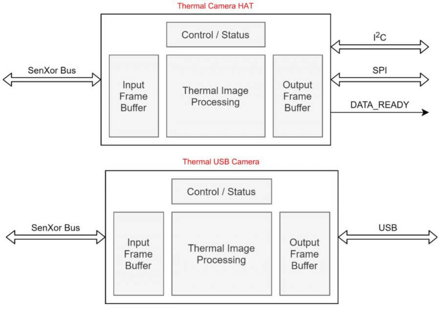
Thermal Camera HAT and Thermal USB Camera are long-wave IR thermal imaging camera modules with 40PIN GPIO header and a USB connector respectively. Support Raspberry Pi, PC, and Android phones. They adopt the hybrid technology of microbolometer and thermopile pixels and can detect the IR distribution of objects in the field of view, turn the data into the surface temperature of the objects by calculation, and then generate thermal images, for easy integration into miscellaneous industrial or intelligent control applications.
Features
- Adopts the hybrid technology of microbolometer and thermopile, 80x62 array pixels.
- Continuous operation and thermal imaging video stream due to shutterless design.
- Noise Equivalent Temperature Difference (NETD) 150mK RMS@1Hz refresh rate.
- Up to 25FPS (Max) thermal imaging video stream output.
- Comes with online resources and manuals (Python demo for Raspberry Pi, Android/Windows host computer and user manual, etc.)
Specification
- POWER SUPPLY: 5V
- OPERATING CURRENT: 61mA@5V
- WAVELENGTH RANGE: 8~14μm
- OPERATING TEMPERATURE: -20~85℃
- TARGET TEMPERATURE: -20~400℃
- REFRESH RATE: 25 FPS (Max)
- FOV: 45°(H)×45°(V)
- NOISE EQUIVALENT TEMPERATURE DIFFERENCE: 150mK
- MEASURING ACCURACY: ±2℃ (ambient temp. 10~70℃)
- DIMENSIONS:
- Thermal Camera HAT: 65.0×30.5mm
- Thermal USB Camera: 62.0×13.0mm
Hardware Description
- Thermal Camera HAT connects to Raspberry Pi series 40 GPIO headers.
- Thermal Camera HAT uses I2C to configure camera registers and SPI to send temperature data.
- Thermal Camera HAT has a RESET button on the board, which can be pressed for hardware reset in case of an exception.
- Thermal USB Camera connects to a Windows PC or Android phone and uses the USB interface to send temperature data.
- Thermal USB Camera board has a RESET button that can be pressed for hardware reset in the event of an exception.
Hardware Connection
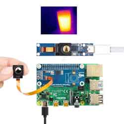
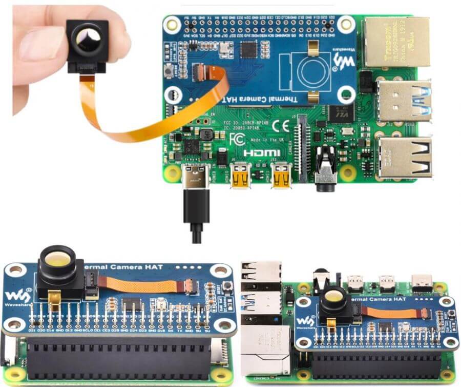
- Thermal Camera HAT Connects to Raspberry Pi:
- When you need to stack additional HAT modules on the Raspberry Pi 4B, you can use a 40-pin GPIO header to connect the Raspberry Pi and the HAT module.
- If you want to extend the camera's connection with a 100mm ribbon cable, you can use it to increase the camera's flexibility and adjust its viewing angle.
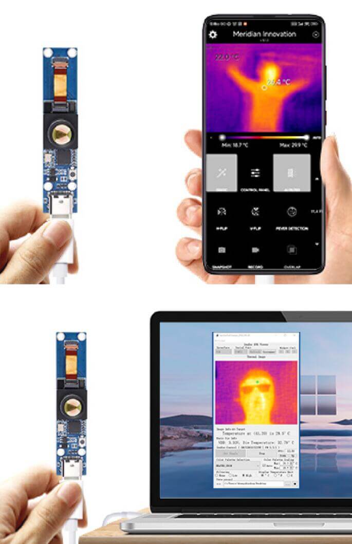
- Thermal USB Camera connects to Windows computers and Android phones.
- Thermal USB Camera accessories have Type-C dual male cables that can be connected to PC and Android phone, if you need to use Type-C to Type-A male port, please purchase separately.
Pin Definition
Configure the camera registers on the Thermal Camera HAT via the I2C and send temperature data using SPI.
| PI-4B | Thermal Camera HAT |
| 5V | 5V |
| GND | GND |
| D2(BCM) | SDA |
| D3(BCM) | SCL |
| D10(BCM) | MOSI |
| D9(BCM) | MISO |
| D11(BCM) | CLK |
| D23(BCM) | nRESET |
| D24(BCM) | D_READY |
| D7(BCM) | SS |
I2C Bus
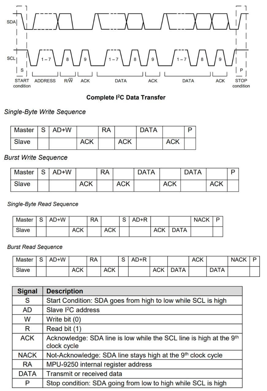
- The read/write timing diagram is shown below, please refer to the datasheet for more details.
- On the Thermal Camera HAT, you can use a 0-ohm resistor to select the I2C address. The default address is 0x40, but you can optionally use 0x41. For more details, please refer to the schematic diagram.
- When the Raspberry Pi 4B acts as the Master device, it pulls down the SDA and SCL pins in sequence to initiate the START condition on the I2C bus. It then writes the device address (7 bits) and the write command (1 bit) for a total of 8 bits of data. If the pin connections are correct, the Thermal Camera HAT, acting as the Slave device, responds with an ACK.
- The Raspberry Pi 4B continues by separately writing the register address (RA) and the register value (DATA) and waits for an ACK response. After completing the write operation, the controller pulls up the SCL and SDA pins in sequence to send the STOP condition.
- If the Raspberry Pi 4B wants to read data from the register (RA), it waits for an ACK response after writing RA and then initiates another START condition. It writes the device address (7 bits) and the read command (1 bit) for a total of 8 bits and waits for an ACK response. After receiving the ACK response, the Thermal Camera HAT returns the DATA. Once the Raspberry Pi 4B receives the DATA, it can maintain the SDA pin at a high level.
- For continuous writing of register values, please refer to the burst Read/Write Sequence in the diagram.
- For the register map, please consult the datasheet.
SPI Bus
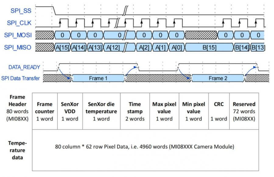
- The SPI timing diagram of Thermal Camera HAT is shown below, please refer to the datasheet for more details.