- sales/support
Google Chat:---
- sales
+86-0755-88291180
- sales01
sales@spotpear.com
- sales02
dragon_manager@163.com
- support
tech-support@spotpear.com
- CEO-Complaints
zhoujie@spotpear.com
- Only Tech-Support
WhatsApp:13246739196
- Purchase/Shipping/Refund
WhatsApp:13424403025
- HOME
- >
- ARTICLES
- >
- Common Moudle
- >
- LCD
2.4inch LCD Module User Guide
Overview
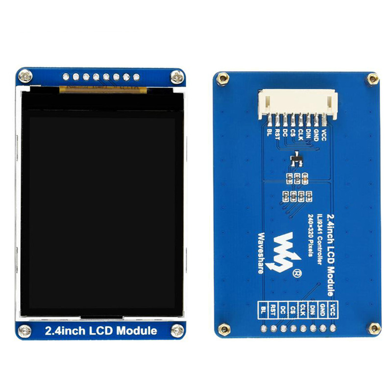
This is a 2.4inch LCD display module, supports 65K RGB colors. The display has 240×320 resolution, SPI Interface.
Specification
- Operating voltage: 3.3V
- Interface: SPI
- LCD Type: TFT
- Controller: IL9341
- Resolution: 240(V) x 320(H)RGB
- Display Size: 36.72(H)x 48.96(V)mm
- Pixel Size: 0.153(H)x 0.153(V)mm
- Dimenstion: 70.5 x 43.3(mm)
Pinout
| PIN | Description |
| VCC | 3.3V |
| GND | GND |
| DIN | SPI data input (MOSI) |
| CLK | SPI clock input (SCLK) |
| CS | Chip selection (low active) |
| DC | Data/Command control |
| RST | Reset |
| BL | Backlight |
Hardware Description
LCD & Controller
The controller of this display supports 12bits, 16bits and 18 bits color format, that are RGB44, RGN565 and RGB66. We use the RGB565 for color displying.
For faster communication and reduce the pins, this display use SPI interface.
Communication protocol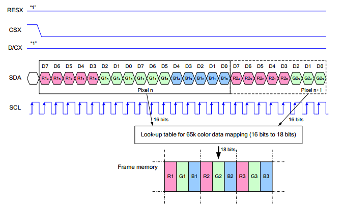
Note: It is not like the traditional SPI protocol, it only uses MOSI to send data from master to slave for the LCD display. For details please refer to Datasheet Page 105.
RESX: Reset, should be pull-down when power on, set to 1 other time.
CSX: Slave chip select. The chip is enabled only CS is set Low
D/CX: Data/Command selection; DC=0, write command; DC=1, write data
SDA: Data transmitted. (RGB data)
SCL: SPI clock
The SPI communication protocol of the data transmission uses control bits: clock phase (CPHA) and clock polarity (CPOL):
CPOL defines the level while the synchronization clock is idle. If CPOL=0, then it is LOW.
CPHA defines at whish clock’s tick the data transmission starts. CPHL=0 – at the first one, otherwise at the second one
This combination of two bits provides 4 modes of SPI data transmission. The commonly used is SPI0 mode, i.e. GPHL=0 and CPOL=0.
According to the figure above, data transmitting begins at the first falling edge, 8bit data are transmitted at one clock cycle. It is SPI0. MSB.