- sales/support
Google Chat:---
- sales
+86-0755-88291180
- sales01
sales@spotpear.com
- sales02
dragon_manager@163.com
- support
tech-support@spotpear.com
- CEO-Complaints
zhoujie@spotpear.com
- Only Tech-Support
WhatsApp:13246739196
- Purchase/Shipping/Refund
WhatsApp:13424403025
- HOME
- >
- ARTICLES
- >
- Common Moudle
- >
- LCD
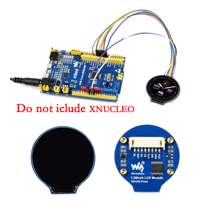
1.28inch LCD Module User Guide
Introduction
1.28inch LCD Display Module, IPS Screen, 65K RGB Colors, 240×240 Resolution, SPI Interface
| More |
Specification
- Operating voltage: 3.3V/5V
- Interface: SPI
- LCD type: IPS
- Controller: GC9A01
- Resolution: 240(H)RGB x 240(V)
- Display size: Φ32.4mm
- Pixel size: 0.135(H)x0.135(V)mm
- Dimension: 40.4×37.5(mm) Φ37.5(mm)
Pinout
| PIN | Description |
| VCC | 3.3V/5V Power input |
| GND | Ground |
| DIN | SPI data input |
| CLK | SPI clock input |
| CS | Chip selection, low active |
| DC | Data/Command control |
| RST | Reset |
| BL | Backlight |
LCD and the controller
- The driver used in this LCD is GC9A01, with a resolution of 240RGB×240 dots and 129600 bytes of GRAM inside. This LCD supports 12-bits/16-bits/18-bits data bus by MCU interface, which are RGB444, RGB565, RGB666.
- For most LCD controllers, the communication method of the controller can be configured, they are usually using 8080 parallel interface, 3-line SPI, 4-line SPI, and other communication methods. This LCD uses a 4-line SPI interface for reducing GPIO and fast speed.LCD
- If you are wondering which point is the first pixel of the screen (because the screen is round), you can understand it as a square screen with an inscribed circle drawn in it, and it only displays the content in this inscribed circle. The pixels in other locations are simply discarded (just like most round smartwatches on the market)
Working Protocol
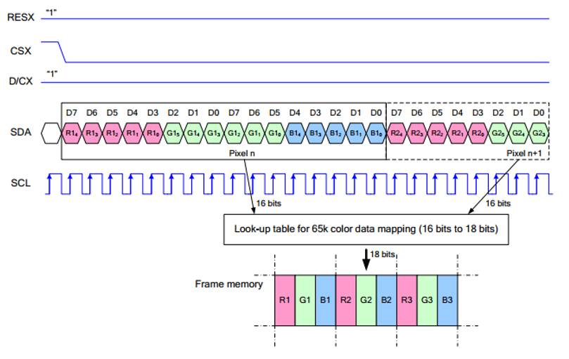
Note: Different from the traditional SPI protocol, the data line from the slave to the master is hidden since the device only has display requirement.
RESX Is the reset pin, it should be low when powering the module and be higher at other times;;
CSX is slave chip select, when CS is low, the chip is enabled.
D/CX is data/command control pin, when DC = 0, write command, when DC = 1, write data
SDA is the data pin for transmitting RGB data, it works as the MOSI pin of SPI interface;
SCL worka s the SCLK pins of SPI interface.
SPI communication has data transfer timing, which is combined by CPHA and CPOL.
CPOL determines the level of the serial synchronous clock at idle state. When CPOL = 0, the level is Low. However, CPOL has little effect to the transmission.
CPHA determines whether data is collected at the first clock edge or at the second clock edge of serial synchronous clock; when CPHL = 0, data is collected at the first clock edge.
There are 4 SPI communication modes. SPI0 is commonly used, in which CPHL = 0, CPOL = 0.