- sales/support
Google Chat:---
- sales
+86-0755-88291180
- sales01
sales@spotpear.com
- sales02
dragon_manager@163.com
- support
tech-support@spotpear.com
- CEO-Complaints
zhoujie@spotpear.com
- Only Tech-Support
WhatsApp:13246739196
- Purchase/Shipping/Refund
WhatsApp:13424403025
- HOME
- >
- ARTICLES
- >
- Common Moudle
- >
- Sensors
TF-Luna LiDAR Range Sensor User Guide
Resource
Demo
Note:
The mode must be determined before power on, to determine if pin 5 is connected.
There are 4 files in the "TF-Luna-LiDAR-Range-Sensor-Demo" folder, corresponding to the 4 hardware platforms, and 2 files in each of the 4 folders, corresponding to the following functions:
File Folder
Description
UART Device is in UART mode for data acquisition IIC Device is in I2C mode for data acquisition
Software
Related File
Introduction
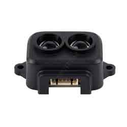
TF-Luna is a single-point ranging Lidar based on the TOF principle. With its unique optical and electrical design, it adopts an 850nm infrared light source to achieve stable, accurate, and highly sensitive distance measurements.
TF-Luna LiDAR Range Sensor has built-in adaptation algorithms for a variety of application environments and targets and is open to a variety of adjustable configurations and parameters. It can ensure excellent range performance in complex environments and meet the needs of customers in complex application scenarios.
Feature
- Compact structure
- Lightweight
- Low-power consumption
- Cost-effective
Application Scenarios
- Assisted Focusing
- Elevator projection
- Intrusion detection
- Level measurement
Specification
Product TF-Luna LiDAR Range Sensor PERFORMANCE Ranging distance 0.2m~8m@90% reflectivity (Indoor 0Klux) 0.2m~2.5m@10% reflectivity (Indoor 0Klux)
0.2m~8m@90% reflectivity (Indoor 90Klux)
0.2m~2.5m@10% reflectivity (Indoor 90Klux)Accuracy ±6cm@(0.2m-3m)
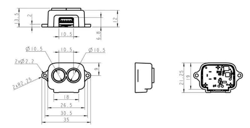
±2%@(3m-8m)Distance resolution 1cm Frame rate 1~250Hz (adjustable) Ambient light resistance 70Klux Operating temperature -10℃~60℃ OPTICAL PARAMETERS Light source VCSEL Central wavelength 850nm Eye safety Class1(IEC60825) Field of view 2° ELECTRICAL PARAMETERS Power supply 3.7V-5.2V Average current ≤70mA Power ≤0.35W Peak current 150mA Communication level LVTTL(3.3V) Communication interface UART/I2C OTHERS Dimension 35mm*21.25mm*13.5mm Case material ABS/PC Storage temperature -20℃~75℃ Weight <5g
Outline Dimensions
Working Principle
This product is based on the TOF (Time of Flight) principle. Specifically, the product periodically sends out a modulated wave of near-infrared light, which is reflected when it meets an object. The time of flight is obtained by measuring the phase difference between the modulated wave and the round trip, and then calculating the relative distance between the product and the measured target, as follows: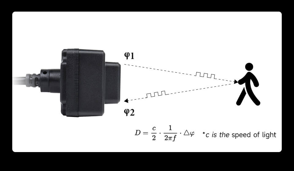
Communication Interface
- UART / I2C
|
|
- I/O mode:
- In I/O output mode, the detection information is indicated by the high and low levels of pin 6. When the output is near-zone level, the output switches to far-zone level after the measured value is greater than the far end point of the hysteresis interval; when the output is far-zone level, the output switches to near-zone level when the measured value is less than the near end point of the hysteresis interval. (High level: 3.3V, low level: 0V)
Wiring Description
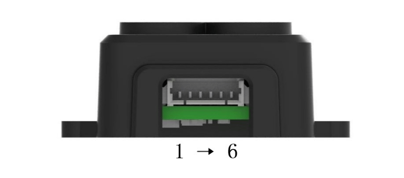
Number
Function
Description
+5V
Power input
2
RXD/SDA
Receive/Data
3
TXD/SCL
Transmit/Clock
4
GND
Ground
5
Interface Input Configuration
Ground: boot it in I2C mode.
NC or connected to 3.3V: start in serial mode6
Multiplexed Output
Switching mode function: Switching output
I2C mode and switch mode off: data ready indication
Software and Use Example
The following section describes how the module can be used under Windows PC, Raspberry Pi, Raspberry Pi Pico, Arduino, ESP32-S3, and other operating system/open-source hardware development platforms.
OS/Hardware Platform
Programming Languages / Software
Windows Host computer software Raspberry Pi Python, C(WiringPi) Raspberry Pi Pico MicroPython Arduino C(Arduino IDE) ESP32 C(Arduino IDE)
Windows Quick Test
Preparation
- TF-Luna
- USB TO TTL
- Windows (Click to download Host computer software)
Hardware Connection
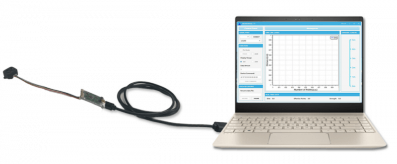
Test Step
- Refer to the hardware connection diagram, connect the TF-Luna module to the computer via the USB TO TTL UART module.
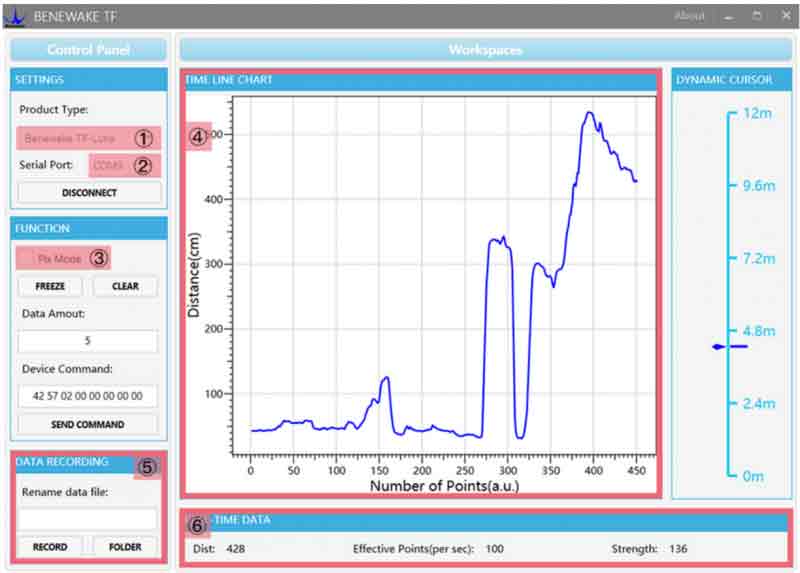
- Open the TF host computer, choose 『① TF-Luna』, and select the occupied serial port that is automatically identified (here is 『② COM9』). Then, click 『CONNECT』 to connect to the upper computer. After a successful connection, the continuous output data image will appear in the right 『④ TIME LINE CHART』 area, and the bottom 『⑥ REAL TIME DATA』 area will show the current test distance (Dist), effective data points per second (Effective Points) and signal strength (Strength) in real-time.
Note:
a) If there is no data in the "④ TIME LINE CHART" area, please check the connection and cable sequence, TF-Luna is powered on successfully, and there will be a faint red light inside the emitting lens when viewed from the front.
b) If TF-Luna is outputting in Pixhawk format, you need to check "③ Pix Mode" first, then the "④ TIME LINE CHART" area will output the data image normally. After Pix Mode is checked, the distance unit will be changed to m.
c) The distance output Dist value is different according to the output unit, the default unit is cm, if the distance unit of TF-Luna is changed to mm by the command, the upper computer can not distinguish, the unit of "④ TIME LINE CHART" is still cm. For example, if the actual distance measured by TF-Luna is 1m, the unit in mm is 1000, and the value read by the upper unit is 1000, but the unit on the upper unit does not change and still shows cm.
Raspberry Pi
Environment Configuration
UART Port Configuration
Since the Raspberry Pi serial port is used for terminal debugging by default, if you need to use the serial port, you need to modify the Raspberry Pi settings. Execute the following command to enter the Raspberry Pi configuration:
sudo raspi-config
Select Interfacing Options -> Serial -> no -> yes, and disable the serial debug function.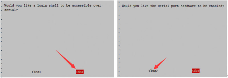
Open the /boot/config.txt file and find the following configuration statement to enable the serial port, if not, add it at the end of the file:
enable_uart=1
And then reboot the Raspberry Pi:
sudo reboot
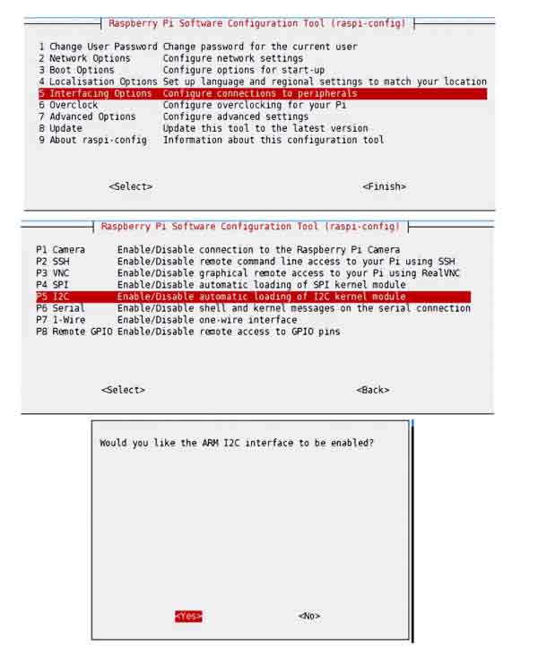
Enable I2C Interface
Open the Raspberry Pi terminal and run the following commands to enter the configuration interface.
sudo raspi-config
Select Interfacing Options -> I2C -> Yes, enable the I2C interface
And then reboot the Raspberry Pi:
sudo reboot
Install WiringPi
Make sure your computer is 32-bit or 64-bit before installation.
32-bit Raspberry Pi System
Execute the following commands separately for WiringPi installation:
wget https://project-downloads.drogon.net/wiringpi-latest.deb
sudo dpkg -i wiringpi-latest.deb
gpio -v
(Optional) If an error occurs during installation, install all missing dependencies and other necessary packages by running the following command, and then re-run the installation command:
sudo apt --fix-broken install
Run "gpio -v" and version 2.52 will appear. If it does not appear, there is an installation error: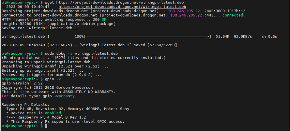
64-bit Raspberry Pi System
Copy the resource package to the Raspberry Pi using the command:
wget https://www.waveshare.com/w/upload/8/8c/WiringPi-master.zip
(optional, you can skip this step if you have used the unzip command) Install the unzip environment:
sudo apt-get install unzip
Go to the file location and execute the unzip command:
unzip WiringPi-master.zip
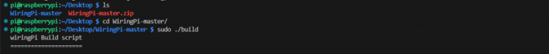
Go to the file directory (go to the "WiringPi-master" folder):
cd WiringPi-master/
Run sudo . /build:
sudo . /build
(optional, see point 4 for errors) If . /build does not work, execute "chmod +x . /build" and then "sudo . /build":
chmod +x . /build
Example: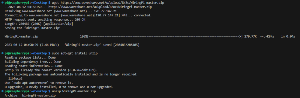
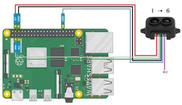
Hardware Connection
UART mode: The fifth pin is overhung or connected to 3.3V before power on, and the communication line is connected to GPIO14 and GPIO15.
IIC mode: The fifth pin is grounded before power on, and the communication line is connected to GPIO2 and GPIO3.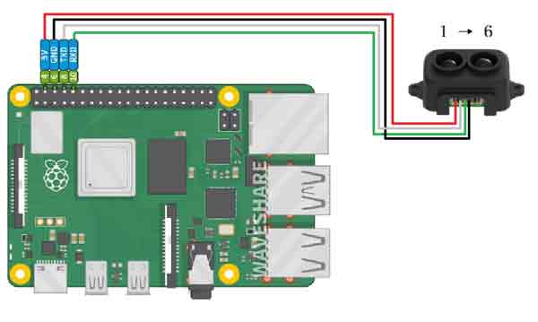
Software Example
Preparation
Download the program packet to the Raspberry Pi:
wget https://www.waveshare.com/w/upload/a/aa/TF-Luna-LiDAR-Range-Sensor-Demo.zip
Unzip the file, create a new file with the same name and unzip it into the corresponding folder:
unzip TF-Luna-LiDAR-Range-Sensor-Demo.zip -d ./TF-Luna-LiDAR-Range-Sensor-Demo
Execution example: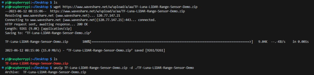
C
The default mode is UART, if you switch the mode, please remember the current mode.
The following operation is to run the "UART" demo as an example. If you are using the I2C interface, please make sure you have connected and set up the corresponding interface, the operation is similar.
Go to the package path "TF-Luna-LiDAR-Range-Sensor-Demo" in the terminal.
cd TF-Luna-LiDAR-Range-Sensor-Demo/
Enter the sample file path, the 4 files under the folder corresponding to the 4 main controls, and the files in the subordinate folder are the data acquisition demos and mode switching demos for the TF-Luna in the corresponding mode (for example: using UART mode to acquire data).
cd Raspberry\ Pi/WiringPi/UART
Use "gcc -o main main.c -lwiringPi" to compile the program.
gcc -o main main.c -lwiringPi
Execute the main program (you need to turn on the relevant functions beforehand, in the Raspberry Pi configuration section).
sudo . /main
Example: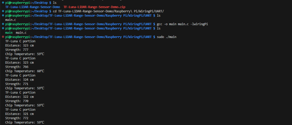
Python
The default mode is UART, if you switch the mode, please remember the current mode.
The following operation is to run the "UART" demos as an example. If you are using the I2C interface, please make sure you have connected and set up the corresponding interface, the operation is similar.
Go to the package path "TF-Luna-LiDAR-Range-Sensor-Demo" in the terminal:
cd TF-Luna-LiDAR-Range-Sensor-Demo/
Enter the sample file path, the 4 files under the folder corresponding to the 4 main controls, and the files in the subordinate folder are the data acquisition demos and mode switching demos for the TF-Luna in the corresponding mode (example: using UART mode to acquire data):
cd Raspberry\ Pi/Python/UART
Run the program:
python3 main.py
Example: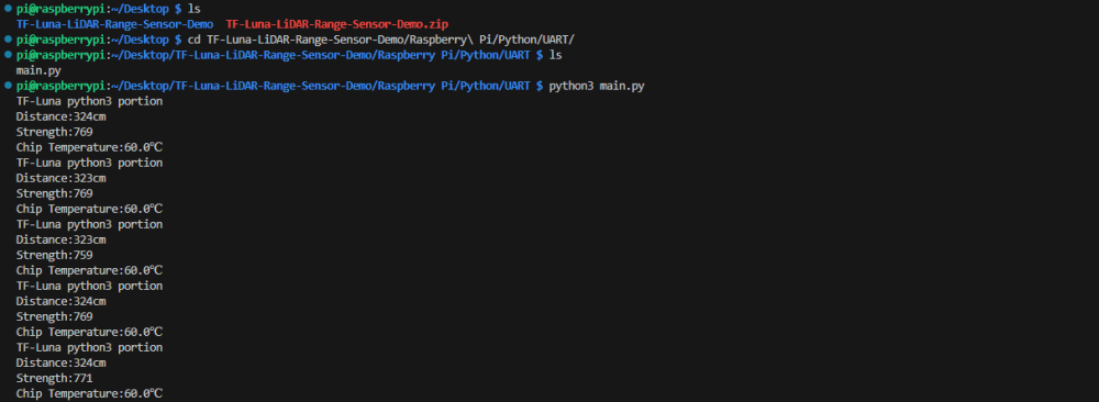
Raspberry Pi Pico
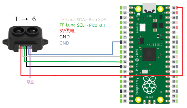
Hardware Connection
UART mode: (the fifth pin is suspended or connected to 3.3V before power on, communication line connected to GPIO8 and GPIO9).
IIC mode: (the fifth pin is grounded before power is on, and the communication line is connected to GPIO8 and GPIO9).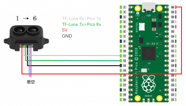
Software Debug
Preparation
- Install Thonny. (Thonny Python IDE (Windows V3.3.3))
- Press the "BOOTSEL" key on the Raspberry Pi Pico, and release it after powering on.
- A new disk will appear on your computer, extract the firmware (Raspberry Pi Pico firmware) and copy the firmware (suffix uf2) to that disk (the disk will automatically disappear if the copy is successful).
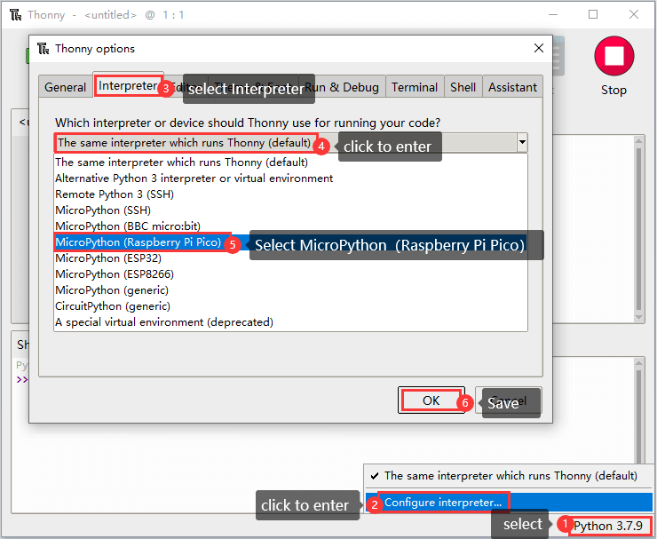
- Open Thonny, click on "Python x.x.x" at the bottom right, and select "Configure interpreter".
- Select "Interpreter" in the pop-up window -> select "MicroPython (Raspberry Pi Pico)" as the interpreter -> select "Auto-detect port" as the port.
- Click on "Stop", and the Shell window will show "MicroPython v1.20.0-50-g786013d46 on 2023-05-04; Raspberry Pi Pico with RP2040 Type "help()" for more information. " is a successful connection.
The successful connection is shown below: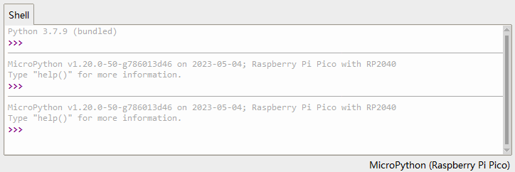
Running Example
The default mode is UART. If you switch the mode, please remember the current mode.
The following operation is to run the "UART" demo as an example. If you are using the I2C interface, please make sure you have connected and set up the corresponding interface, the operation is similar.
- Open the downloaded demo example. (demo example).
- Enter "TF-Luna-LiDAR-Range-Sensor-Demo" -> "Raspberry Pi Pico".
- Under the "Raspberry Pi Pico" folder, there are 2 files in order, each representing its own function.
- Go to the "UART" folder and use Thonny to open UART.py (an example is to get data in UART mode).
- Click Run in Thonny.
The debug effect is shown below: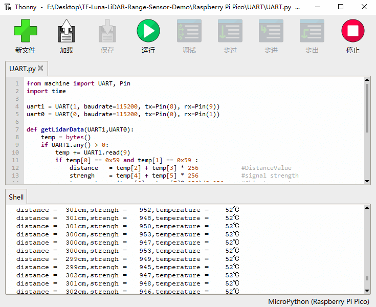
Working with Arduino
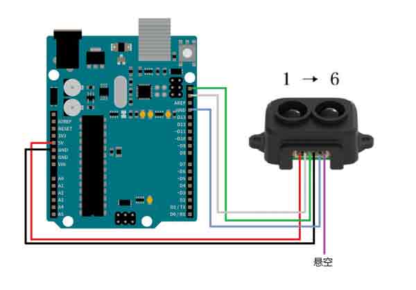
Hardware Connection
UART mode: (the fifth pin is not connected or connected to 3.3V before power on, the signal line connected to D0, D1) IIC mode: (the fifth pin is grounded before power on, the signal line connected to SDA, SCL).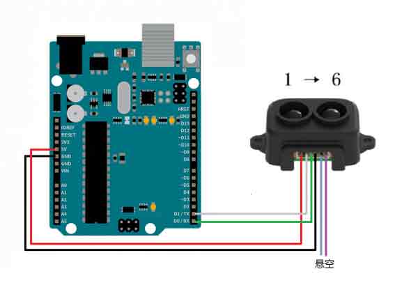
Software Debug
The default mode is UART, if you switch modes, please remember the current mode. The following operation is based on running the "UART" demo as an example. If you are using the I2C interface, please make sure that the corresponding interface is connected and set up, and the operation is similar.
- Install Arduino.
- Open the downloaded demo example. (demo example).
- Go to "TF-Luna-LiDAR-Range-Sensor-Demo" -> "Arduino".
- Under the "Arduino" folder, there are 4 files in order, each representing its own function.
- Enter the "UART" file folder, use Arduino IDE to open the UART.ino. (Example for data acquisition in UART mode).
- Connect the Arduino board, and select the corresponding development board and port on the Arduino IDE.
- Click to verify and click to upload.
- As it is in UART mode, you can wait for uploading and then connect the device to the Arduino board. (Make sure that the D0 and D1 port of the Arduino has not connected to the device when you upload.)
- Example:
- Debugging effect as shown below:
Working with ESP32
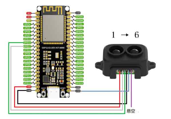
ESP32-S3-DEV-KIT-N8R8 development board is used in this example.
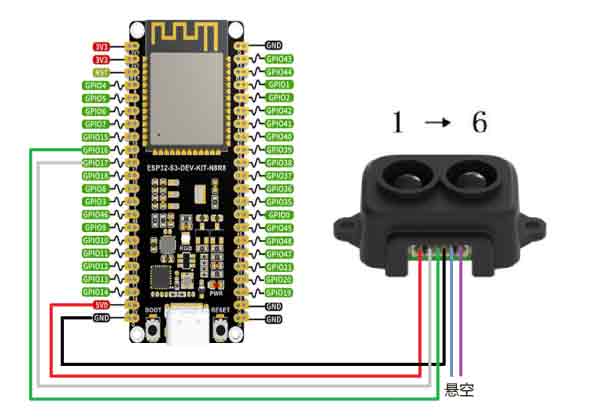
Hardware Connection
UART mode: (the fifth pin is overhung or connected to 3.3V before power on, the signal line connected to GPIO16 and GPIO17).
IIC mode: (the fifth pin is grounded before power is on, and the signal line is connected to GPIO16 and GPIO17).
Software Debugging
Preparation
- Install Arduino.
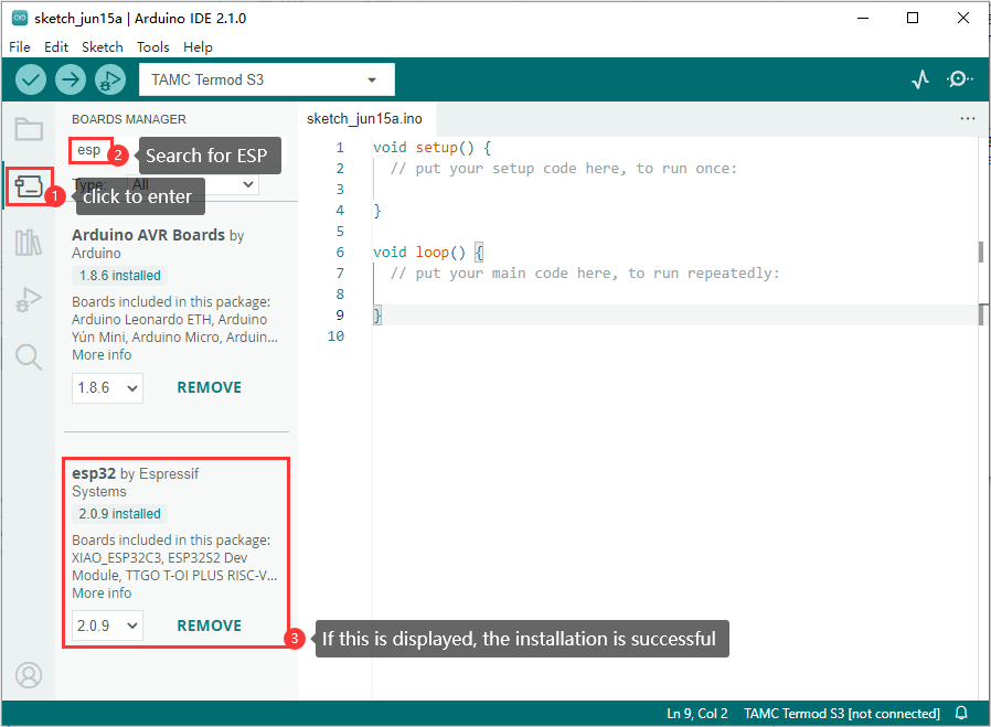
- Install the ESP32 library in the Arduino IDE. ()
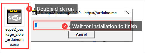
- Go to the file opened in point 2 and select the corresponding version of ESP32 to download.
- Double click the APP downloaded:
- Open the Arduino IDE to check whether the installation is successful.
Running Example
The default mode is UART, and you need to remember it before switching to other modes. The following operation is based on running the "UART" demo as an example. If you are using the I2C interface, please make sure that you have connected and set up the corresponding interface, and do the same.
- Open the downloaded sample program (demo example).
- Go to "TF-Luna-LiDAR-Range-Sensor-Demo" -> "ESP32".
- Under the folder "ESP32", there are 2 files in order, representing their respective functions.
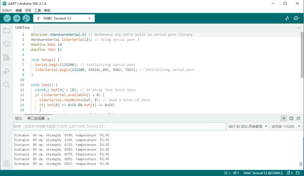
- Enter the "UART" folder, and use Arduino IDE to open UART.ino (an example is to get data in UART mode).
- Connect the ESP32 board, and select the corresponding development board, and port on the Arduino IDE.
- Click verify, then click upload.
- The following is the operation process:
- The debugging effect is shown below:
Resource
Demo
Note:
The mode must be determined before power on, to determine if pin 5 is connected.
There are 4 files in the "TF-Luna-LiDAR-Range-Sensor-Demo" folder, corresponding to the 4 hardware platforms, and 2 files in each of the 4 folders, corresponding to the following functions:
File Folder
Description
UART Device is in UART mode for data acquisition IIC Device is in I2C mode for data acquisition