- sales/support
Google Chat:---
- sales
+86-0755-88291180
- sales01
sales@spotpear.com
- sales02
dragon_manager@163.com
- support
tech-support@spotpear.com
- CEO-Complaints
zhoujie@spotpear.com
- Only Tech-Support
WhatsApp:13246739196
- Purchase/Shipping/Refund
WhatsApp:13424403025
- HOME
- >
- ARTICLES
- >
- Common Moudle
- >
- USB HUB
USB-TO-RS232-485-B User Guide
Overview
Introduction
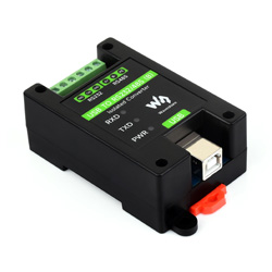
USB TO RS232/485 (B), an industrial-grade USB to RS485/422 isolated converter, adopts the original FT232RNL, an industrial rail case design, built-in protection circuits such as power isolation, ADI magnetic coupling isolation, and TVS. USB TO RS232/485 (B) is easy to operate, and can automatically transmit and receive without delay. It features fast communication speed, stability, reliability, and safety, which can be applied to various industrial control devices or applications with high communication requirements.
Features
- Onboard Original FT232RL and SP485EEN chip. Fast communication, stable and reliable, better compatibility.
- Onboard unibody power supply isolation, provides stable isolated voltage and needs no extra power supply for the isolated terminal.
- Onboard unibody digital isolation, allows signal isolation, high reliability, strong anti-interference, and low power consumption.
- Onboard TVS (Transient Voltage Suppressor), effectively suppresses surge voltage and transient spike voltage in the circuit, lightning-proof & anti-electrostatic.
- Onboard self-recovery fuse and protection diodes, ensure the current/voltage stable outputs, provide over-current/over-voltage proof, and improve shock resistance.
- Onboard 120R terminal resistor on the RS485/RS422 ports, enabled by default, configurable by jumper.
- 3x LEDs for indicating the power and transceiver status.
- Industrial rail-mount ABS case design, small in size, easy to install, and cost-effective.
Specification
| Product Type | Industrial Isolated USB to RS232/RS485 converter | |
| Host Interface | USB | |
| Device Interface | RS232/RS485 | |
| USB Interface | Operating Level | 5V |
| Interface | USB-B | |
| Protection | 200mA self-recovery fuse, isolated output | |
| Transmission Distance | About 5m | |
| Isolated RS232 Interface | Form Factor | Screw terminal |
| Transmission Distance | About 15m | |
| Transmission Mode | Point to point | |
| Baud rate | 300 bps ~ 921600bps | |
| Isolated RS485 Interface | Form factor | Screw terminal |
| Direction Control | Hardware automatic control | |
| Protection | Provide 600W lightningproof, anti-surge and 15KV ESD protection (onboard 120R balancing resistor) | |
| Transmission Distance | About 1200m (at low rate) | |
| Transmission Mode | Point to multi-point (up to 32 nodes, add a relay for up to 16 nodes) | |
| Baud Rate | 300 bps ~ 921600bps | |
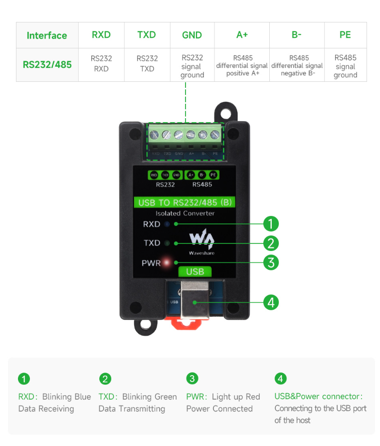
| Indicator | PWR | Power indicator, connect to USB, the red LED is on when the voltage is detected |
| TXD | Tx indicator, green LED is on when data is sent from the USB port | |
| RXD | Rx indicator, blue LED is on when data is sent from the device port | |
| Usage Environment | Temperature range | -15℃ ~ 70℃ |
| Humidity range | 5% ~ 95%RH | |
| OS | Mac, Linux, Android, Windows 11 / 10 / 8.1 / 8 / 7 | |
| Appearance | Case | Rail-mount ABS eco-friendly case, for 35mm DIN rail |
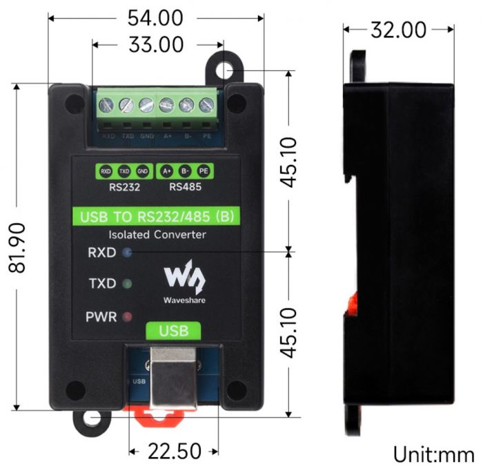
| Dimensions | 81.9 × 54.0 × 32.0mm | |
Onboard Interface
Dimensions
Driver Installation
USB Driver Installation
- Download the driver file VCP Driver.
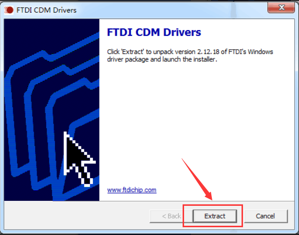
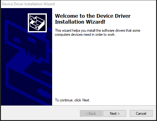
- Double-click CDM212364_Setup.exe to install it following the steps below:
- Click on Extract, and then "Next".
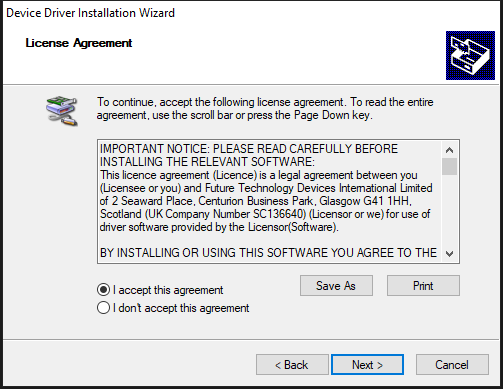
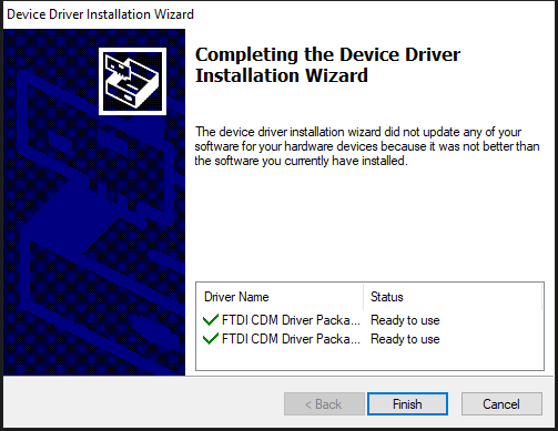
- Click on "I accept this agreement" and Next, and then Finish.
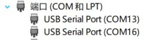
- After connecting to the PC, you can see the available port on the device manager:
Hardware Test
Test environment: PC (Windows system)
Required accessories:
- USB TO RS485/422 (B) x 2pcs
- USB Type-A to Type-C
- Cables
RS232 test
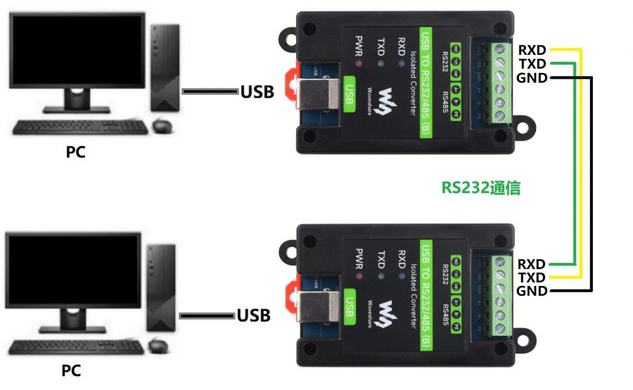
- To connect the RS232 port of the USB TO RS232/485 (B) module, connect RXD to TXD, and GND to GND. Refer to the connection diagram below:
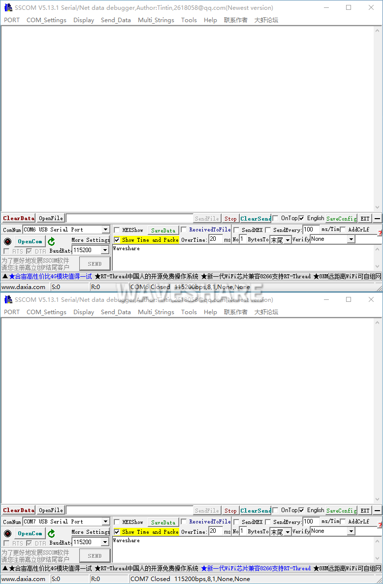
- Open two SSCOM serial port debugging assistants on the computer, and open the corresponding port number.
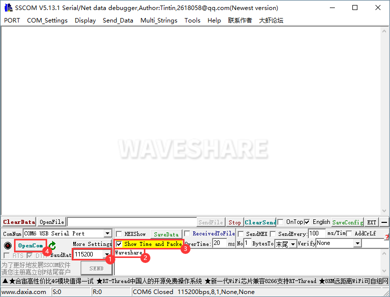
- Select the baud rate as 115200, input the characters to be sent, and is better to select the "Show time and package", and open the serial port.
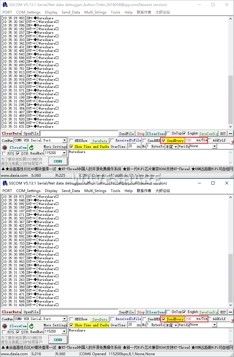
- Both select the 100ms of the SSCOM, and you can see the normal data transmission in these two Windows, and the testing effect:
RS485 Test
- Connect the RS485 port of the USB TO RS232/485 (B) module, i.e. A+ --> A+, B- --> B-, PE --> PE, and refer to the connection diagram below:
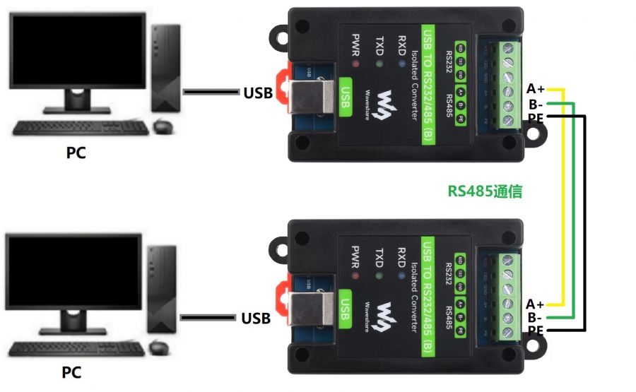
- Open two SSCOM windows, and open the corresponding port number.
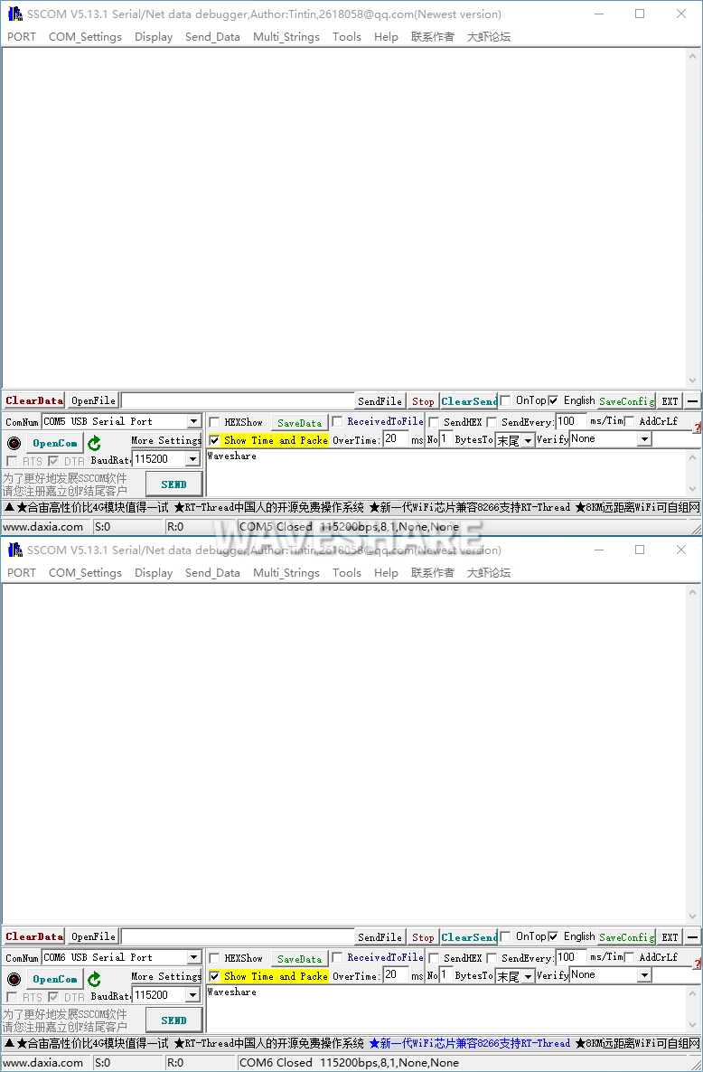
- Select the baud rate as 115200, and input the characters to be sent, and it is better to check "show time and package", click on Open serial port:
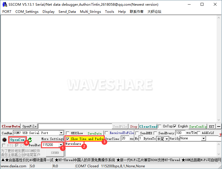
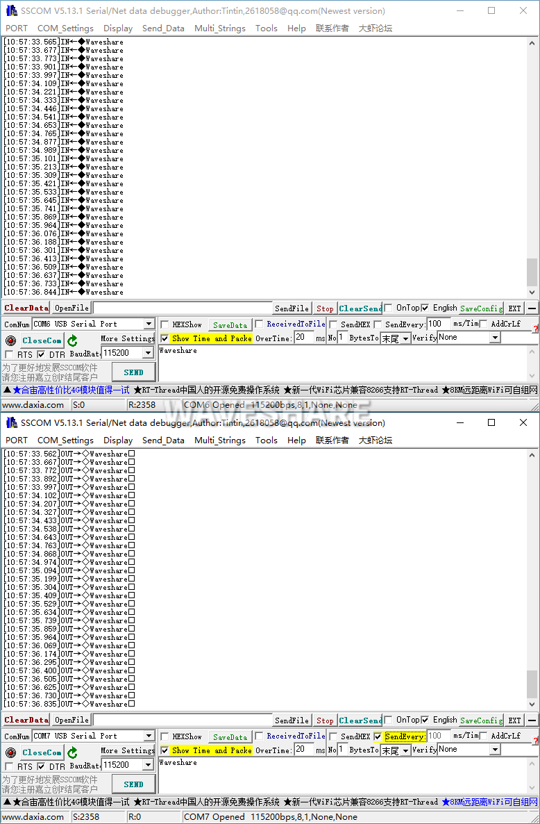
- Select one SSCOM, send it in 100ms intervals, and then you can see the two windows transmit the data normally, and the testing effect as shown below:
Resource
Datasheet
Software
- VCP Driver (or download from FTDI official website)
- SSCOM
Support
Monday-Friday (9:30-6:30) Saturday (9:30-5:30)
Email: services01@spotpear.com