- sales/support
Google Chat:---
- sales
+86-0755-88291180
- sales01
sales@spotpear.com
- sales02
dragon_manager@163.com
- support
tech-support@spotpear.com
- CEO-Complaints
zhoujie@spotpear.com
- Only Tech-Support
WhatsApp:13246739196
- Purchase/Shipping/Refund
WhatsApp:13424403025
Raspberry Pi PICO RP2040-PiZero User Guide
Overview
Introduction
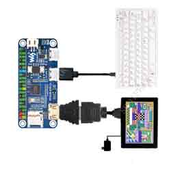
RP2040-PiZero is a high-performance and cost-effective microcontroller board designed by Waveshare, with an onboard DVI interface, TF card slot, and PIO-USB port, compatible with Raspberry Pi 40PIN GPIO header, easy to develop and integrate into the products.
Features
- RP2040 microcontroller chip designed by Raspberry Pi in the United Kingdom.
- Dual-core ARM Cortex M0+ processor, flexible clock running up to 133 MHz.
- 264KB of SRAM, and 16MB of onboard Flash memory.
- Type-C interface, keep up with the trend of The Times, no need to tangle the positive and negative plug.
- The onboard DVI interface can drive most HDMI screens (DVI compatibility required).
- Supports use as a USB host or slave via onboard PIO-USB port.
- Onboard TF card slot for reading and writing TF cards.
- Onboard Lithium battery recharge/discharge header, suitable for mobile scenarios.
- USB 1.1 with device and host support.
- Supports low-power sleep and dormant modes.
- Drag-and-drop programming using mass storage over USB.
- Low-power sleep and dormant modes.
- 2 × SPI, 2 × I2C, 2 × UART, 4 × 12-bit ADC, 16 × controllable PWM channels.
- Accurate clock and timer on-chip.
- Temperature sensor.
- Accelerated floating-point libraries on-chip.
- 8 × Programmable I/O (PIO) state machines for custom peripheral support.
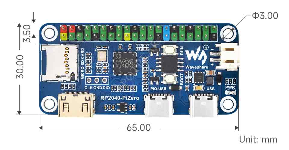
Dimensions
Pico Quick Start
Firmware Download
- MicroPython Firmware Download

- C_Blink Firmware Download

Text Tutorial
Introduction
MicroPython Series
- 【MicroPython】 machine.Pin Function
- 【MicroPython】 machine.PWM Function
- 【MicroPython】 machine.ADC Function
- 【MicroPython】 machine.UART Function
- 【MicroPython】 machine.I2C Function
- 【MicroPython】 machine.SPI Function
- 【MicroPython】 rp2.StateMachine
C/C++ Series
For C/C++, it is recommended to use Pico VS Code for development. This is a Microsoft Visual Studio Code extension designed to make it easier for you to create, develop, and debug projects for the Raspberry Pi Pico series development board. Whether you are a beginner or an experienced professional, this tool can help you confidently and easily develop Pico. Below we will introduce how to install and use the extension.
- Official website tutorial: https://www.raspberrypi.com/news/pico-vscode-extension/.
- This tutorial is applicable to Raspberry Pi Pico, Pico2, and our company's RP2040 and RP2350 series development boards.
- The development environment defaults to Windows as an example. For other environments, please refer to the official website tutorial for installation.
Arduino IDE Series
Install Arduino IDE
- Download the Arduino IDE installation package from Arduino website.
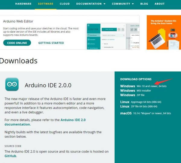
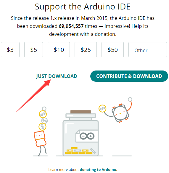
- Just click on "JUST DOWNLOAD".
- Click to install after downloading.
- Note: You will be prompted to install the driver during the installation process, we can click Install.
Install Arduino-Pico Core on Arduino IDE
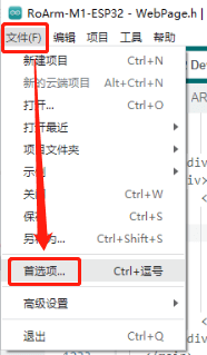
- Open Arduino IDE, click the File on the left corner and choose "Preferences".
- Add the following link in "Additional boards manager URLs", then click OK.
https://github.com/earlephilhower/arduino-pico/releases/download/global/package_rp2040_index.json
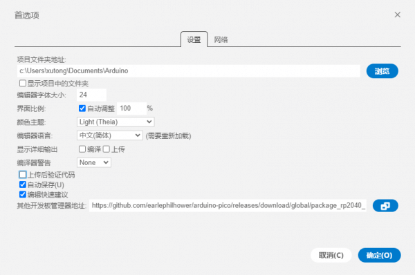
Note: If you already have the ESP32 board URL, you can separate the URLs with commas like this:https://dl.espressif.com/dl/package_esp32_index.json,https://github.com/earlephilhower/arduino-pico/releases/download/global/package_rp2040_index.json
- Click on Tools -> Board -> Board Manager -> Search for pico, it shows installed since my computer has already installed it.
Pico Get Start 05.png Pico Get Start 06.png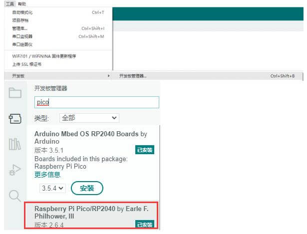
Upload Demo At the First Time
- Press and hold the BOOTSET button on the Pico board, connect the Pico to the USB port of the computer via the Micro USB cable, and release the button when the computer recognizes a removable hard drive (RPI-RP2).
- Download the demo from #Resource, open the D1-LED.ino under arduino\PWM\D1-LED path.
- Click Tools -> Port, remember the existing COM, do not need to click this COM (different computers show different COM, remember the existing COM on your computer).
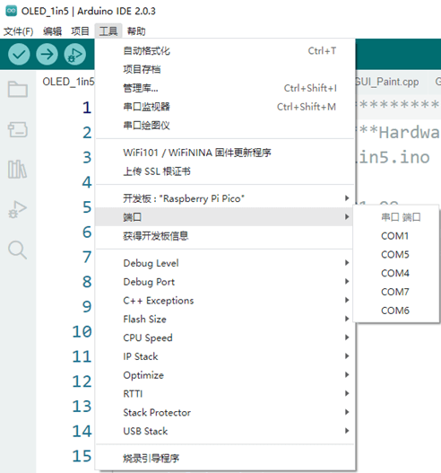
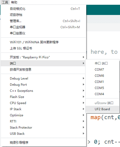
- Connect the driver board to the computer with a USB cable, then click Tools -> Ports, select uf2 Board for the first connection, and after the upload is complete, connecting again will result in an additional COM port.
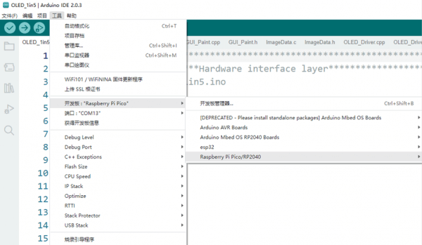
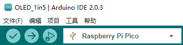
- Click Tools -> Board -> Raspberry Pi Pico/RP2040 -> Raspberry Pi Pico.
- After setting, click the right arrow to upload.
- If you encounter problems during the period, you need to reinstall or replace the Arduino IDE version, uninstall the Arduino IDE clean, after uninstalling the software you need to manually delete all the contents of the folder C:\Users\[name]\AppData\Local\Arduino15 (you need to show the hidden files in order to see it) and then reinstall.
Open Source Demo
- MicroPython Demo (GitHub)
- MicroPython Firmware/Blink Demo (C)
- Official Raspberry Pi C/C++ Demo
- Official Raspberry Pi MicroPython Demo
- Arduino Official C/C++ Demo
Sample Demo
C Demo
01-DVI
- This demo is based on the modification of Wren6991 PicoDVI.
Main Directory Analysis
- apps: the demo source codes.
- assets: the original picture and picture header file.
- include: the default pin configuration header file.
- libvi: the related DVI driver source code.
- libgui: the related GUI source code.
Hello DVI Demo
- The Hello DVI demo is located in the "hello_dvi" file of the "apps" directory.
- Scrolling display of a test image with a resolution of 320x240p in RGB565 format is in a 640x480p 60Hz DVI mode.
Gui Demo
- The Gui demo is located in the "gui demo" file of the "apps" directory.
- In 640x480p 60Hz DVI mode, it sequentially displays white, red, yellow, green, cyan, blue, purple, and black screens, followed by the GUI image.
02-USB
- This demo is based on the modification of sekigon-gonnoc Pico-PIO-USB.
Main Catalog Analysis
- examples: the demo source code.
- src: the related PIO-USB driver source code.
capture_hid_report Demo
- capture_hid_report demo is located on the capture_hid_report of the examples directory.
- PIO-USB serves as a sample demo for the USB host and can be used to print the HID report received from the USB device.
usb_device Demo
- The "usb_device" demo is located in the "usb_device" directory of the "examples" directory.
- The PIO-USB example emulates a mouse and moves the mouse cursor every 0.5 seconds.
Host_hid_to_device_cdc Demo
- The "Host_hid_to_device_cdc" demo is located in the "Host_hid_to_device_cdc" directory of the "examples" directory.
- Host_hid_to_device_cdc" is similar to "capture_hid_report" and it prints mouse/keyboard reports from the host port to the device port's CDC.
03-MicroSD
Main Directory Analysis
- tests: the source code for testing.
- FatFs_SPI: the related MicroSD source code.
Demo
- Using terminal tools such as Putty or MobaXterm, open the USB serial port corresponding to RP2040-PiZero.
- When you press Enter, it will display the following information:
>
- Input "help" command to display the following information:
setrtc <DD> <MM> <YY> <hh> <mm> <ss>:
  Set Real Time Clock
  Parameters: new date (DD MM YY) new time in 24-hour format (hh mm ss)
	e.g.:setrtc 16 3 21 0 4 0

date:
 Print current date and time

lliot <drive#>:
 !DESTRUCTIVE! Low Level I/O Driver Test
	e.g.: lliot 1

format [<drive#:>]:
  Creates an FAT/exFAT volume on the logical drive.
	e.g.: format 0:

mount [<drive#:>]:
  Register the work area of the volume
	e.g.: mount 0:

unmount <drive#:>:
  Unregister the work area of the volume

chdrive <drive#:>:
  Changes the current directory of the logical drive.
  <path> Specifies the directory to be set as current directory.
	e.g.: chdrive 1:

getfree [<drive#:>]:
  Print the free space on drive

cd <path>:
  Changes the current directory of the logical drive.
  <path> Specifies the directory to be set as current directory.
	e.g.: cd 1:/dir1

mkdir <path>:
  Make a new directory.
  <path> Specifies the name of the directory to be created.
	e.g.: mkdir /dir1

ls:
  List directory

cat <filename>:
  Type file contents

simple:
  Run simple FS tests

big_file_test <pathname> <size in bytes> <seed>:
 Writes random data to file <pathname>.
 <size in bytes> must be multiple of 512.
	e.g.: big_file_test bf 1048576 1
	or: big_file_test big3G-3 0xC0000000 3

cdef:
  Create Disk and Example Files
  Expects card to be already formatted and mounted

start_logger:
  Start Data Log Demo

stop_logger:
  Stop Data Log Demo
Arduino Demo
01-DVI
- This demo is based on the modification of Wren6991 PicoDVI.
Hello Dvi
- The Hello DVI demo is located in the "Hello DVI" directory.
- Scrolling display of a test image with a resolution of 320x240p in RGB565 format is in a 640x480p 60Hz DVI mode.
02-USB
- This demo is based on the modification of sekigon-gonnoc Pico-PIO-USB.
Install Dependency Library
This demo requires the Pico PIO USB library to be installed as follows:
1. Install Pico PIO USB library: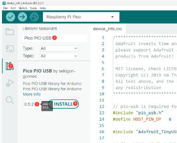
2. Select "Install All":
3. Successfully installed:
4. Modify the USB Stack configuration: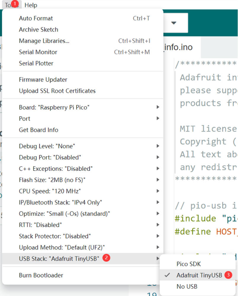
device_in Demo
- The device_in demo is located in the "device_in" directory.
- The PIO-USB will be used as a USB host example demo for printing HID reports received from the device.
- After the program is successfully uploaded, open the serial port monitor, connect the USB device, and press the "RUN" button to restart RP2040-PiZero
Core1 setup to run TinyUSB host with pio-usb
Device attached, address = 1
Device 1: ID 05ac:0256
Device Descriptor:
  bLength             18
  bDescriptorType     1
  bcdUSB              0110
  bDeviceClass        0
  bDeviceSubClass     0
  bDeviceProtocol     0
  bMaxPacketSize0     64
  idVendor            0x05ac
  idProduct           0x0256
  bcdDevice           0310
  iManufacturer       1     CX
  iProduct            2     2.4G Wireless Receiver
  iSerialNumber       0
  bNumConfigurations  1
TinyUSB Dual Device Info Example
03-MicroSD
Demo
- Insert the SD card and run the demo to write data to the SD card.
Hello, world!
V2-Version Card
R3/R7: 0x1aa
R3/R7: 0x40ff8000
R3/R7: 0xc0ff8000
Card Initialized: High Capacity Card
SD card initialized
SDHC/SDXC Card: hc_c_size: 30475
Sectors: 31207424
Capacity:    15238 MB
Goodbye, world!
Resource
Demo
Schematic
Official Resources
Raspberry Pi Official Datasheet
- Raspberry Pi Pico Get Started MicroPython
- Related Raspberry Pi Books Download
- Get Started With Pico Manual
- Pico C SDK User Manual
- Pico Python SDK User Manual
- Raspberry Pi Pico Schematic
- Pico Pinout
- Pico Datasheet
- Rp2040 Datasheet
- Hardware Design Manual
Raspberry Pi Open-source Demo
Development Software
- Zimo221.7z
- Image2Lcd.7z
- Font Library Tutorial
- Image Extraction Tutorial
- Thonny Python IDE (Windows V3.3.3)
Support
To:
Dear Customers, There may be a lag of several hours before we could process your order, depending on the time difference between your location and ours. Sincerely hoping your understanding!
Email(support)
services01@spotpear.com