- sales/support
Google Chat:---
- sales
+86-0755-88291180
- sales01
sales@spotpear.com
- sales02
dragon_manager@163.com
- support
tech-support@spotpear.com
- CEO-Complaints
zhoujie@spotpear.com
- Only Tech-Support
WhatsApp:13246739196
- Purchase/Shipping/Refund
WhatsApp:13424403025
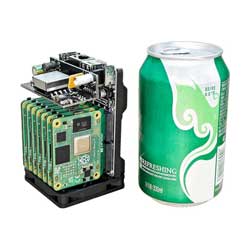
NanoCluster-Basic-Package Switch Management
1. Introduction
NanoCluster is equipped with the JL6108 Gigabit switch chip, which is based on the RISC-V architecture. It can be used as a plug-and-play switch or as a locally managed Layer 2 switch, supporting configuration via a web interface. Its main features include:
- System Management: Displays system information, supports reboot, factory reset, and firmware upgrades
- Network Configuration: Supports static IP and DHCP dynamic IP configuration
- Port Management: Enables/disables ports, configures link speed, and manages flow control
- Port Aggregation: Supports port binding to increase bandwidth utilization
- Security and Isolation: Port isolation to prevent data leakage
- Traffic Monitoring: Port MIB statistics and traffic analysis
- Loop Protection: Prevents network loops to enhance stability
- VLAN Configuration: Supports MTU VLAN, port-based VLAN, 802.1Q VLAN, and PVID settings
- QoS Configuration: Manages traffic priority based on port, PCP, and DSCP
- Bandwidth and Storm Control: Supports port-based bandwidth limitation and broadcast storm suppression
The default firmware management interface is in English. You can switch to a bilingual (Chinese/English) interface by updating via OTA.
The switch management interface currently has response issues on Linux. For better compatibility, it is recommended to log in to the switch management interface using Windows.
2. Port Allocation
The cluster backplane connects to each core board (SOM) via the JL6108 switch. The port allocation is as follows:
| Switch Port | Connected Device |
|---|---|
| Port 1 | Slot 7 |
| Port 2 | Slot 6 |
| Port 3 | Slot 5 |
| Port 4 | Slot 4 |
| Port 5 | Slot 3 |
| Port 6 | Slot 2 |
| Port 7 | Slot 1 |
| Port 8 | Cluster backplane RJ45 port (for external network connection) |
3. User Guide
3.1. Logging into the Web Management Interface
Ensure Device Connection
Make sure the NanoCluster is powered on and connected to the management host via an Ethernet cable.Configure IP Address
The switch's default IP address is 10.10.11.10/24. Ensure the management host has an IP in the same subnet, e.g., 10.10.11.x (where x is between 1-254 but not 10), with a subnet mask of 255.255.255.0.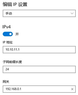
Access the Management Interface
Open a browser and enterhttp://10.10.11.10, then press Enter to reach the login page.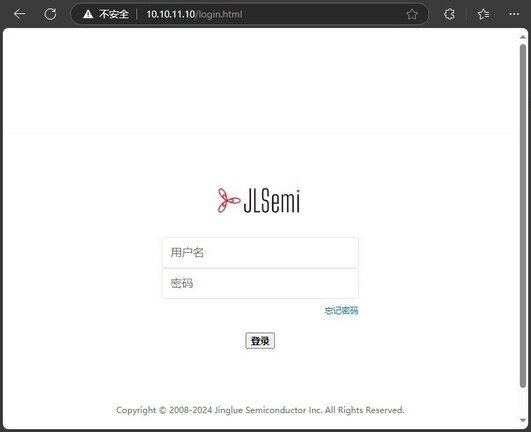
Login to the Management System
Enter the admin username and password (both default toadmin), then click Login to access the main interface.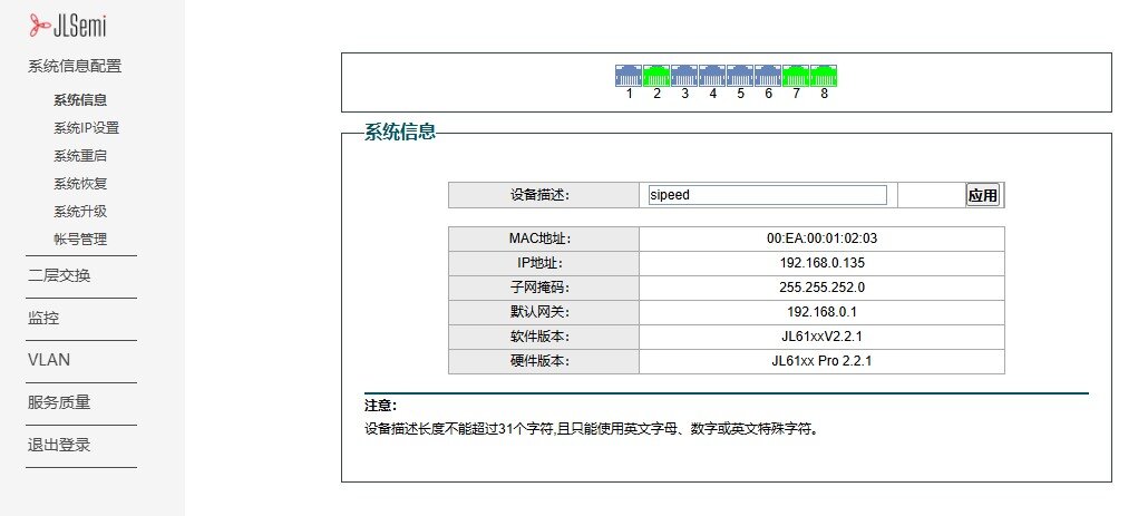
4. Basic Configuration
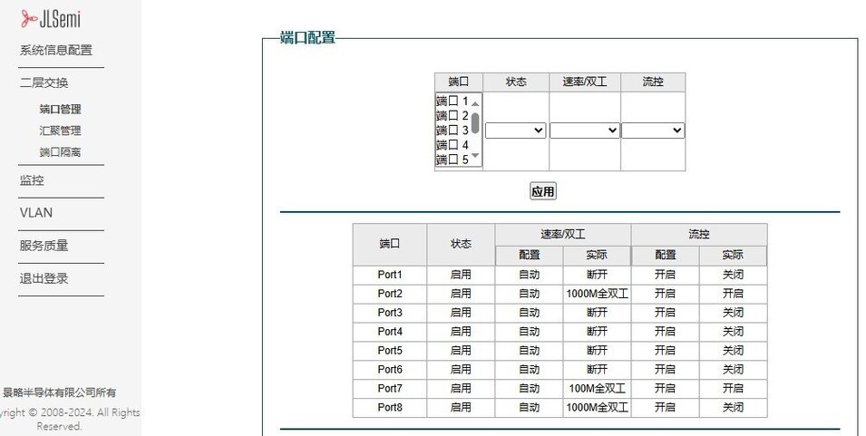
4.1. Port Management
The JL6108 switch provides port status management, supporting port enable/disable, speed configuration, and flow control.
- Enable/Disable Ports: Navigate to the Port Management page, select the desired port, and enable or disable it.
- Modify Port Speed: Supports 10Mbps / 100Mbps / 1000Mbps modes.
- Flow Control: Can be enabled to prevent packet loss.
4.2. VLAN Configuration
VLAN (Virtual Local Area Network) is used to segment different network areas, prevent broadcast storms, and enhance security.
4.2.1. Configuring Port VLAN#
Access the Port VLAN Page
Navigate toVLAN>>Port VLANin the Web interface.Enable Port VLAN
Check the "Enable Port VLAN" option and clickApply.Create VLAN 2 and Assign Ports
- Enter
2in the VLAN ID field - Select Ports 2 to 4
- Click
Applyto save the configuration
- Enter
View the Port Member Table
After configuration, Ports 2-4 will be automatically removed from VLAN 1 and assigned to VLAN 2.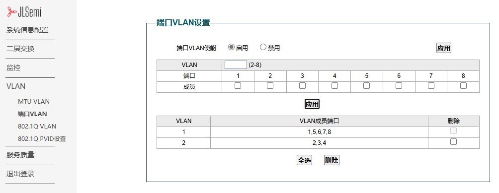
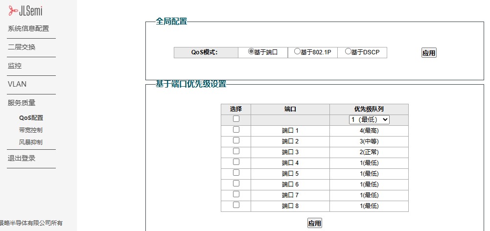
4.3. QoS Configuration (Traffic Prioritization)
QoS ensures stable performance for high-priority traffic such as video conferencing and VoIP:
- Navigate to "QoS Settings"
- Select Port-Based / 802.1P / DSCP QoS strategy
- Set High / Medium / Low Priority Queues
- Save the settings to apply the QoS rules
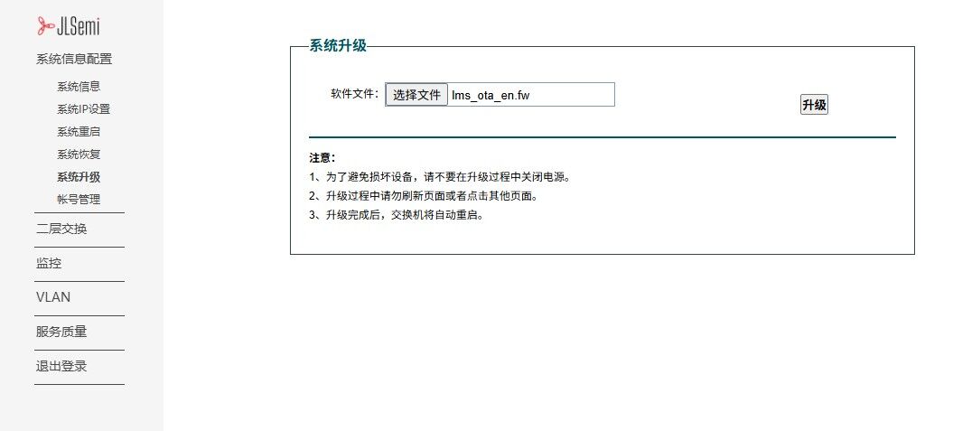
4.4. OTA Update
Firmware download link: Click to download OTA firmware
- Open the Web management interface and navigate to:
System Information Configuration→System Upgrade - Click Select File and select the appropriate firmware file for the upgrade:
- English interface firmware:
lms_ota_en.fw - Chinese interface firmware:
lms_ota_zh.fw
- English interface firmware:
- Click Upgrade. The system will display the upgrade progress and automatically verify the firmware.
- After the upgrade is complete, the device will automatically reboot to apply the new firmware.
- If the upgrade fails, power cycle the device, re-enter the management address to access the upgrade page, and repeat the upgrade process.
5. Additional Configuration
The JL6108 switch also supports more advanced features. For detailed configuration instructions, please refer to the official manual.
Click here to view the full manual
We provide the JL6108 SDK based on the RISC-V architecture. Users can download the SDK and develop independently from the following link: