


- sales/support
Google Chat:---
- sales
+86-0755-88291180
- sales01
sales@spotpear.com
- sales02
dragon_manager@163.com
- support
tech-support@spotpear.com
- CEO-Complaints
zhoujie@spotpear.com
- Only Tech-Support
WhatsApp:13246739196
- Purchase/Shipping/Refund
WhatsApp:13424403025
- HOME
- >
- ARTICLES
- >
- Common Moudle
- >
- ESP
ESP32-S3-Touch-LCD-1.85C User Guide
Overview
Introduction
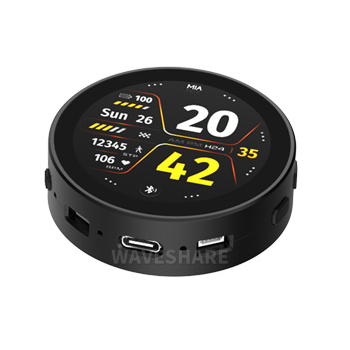
ESP32-S3-Touch-LCD-1.85C is a microcontroller development board that supports 2.4GHz Wi-Fi and BT BLE 5. It integrates large capacity Flash and PSRAM and has onboard 1.85inch round touchscreen, can smoothly run GUI programs such as LVGL. Combined with various peripheral interfaces, it is suitable for the quick development of the HMI and other ESP32-S3 applications.
Features
- Equipped with high-performance Xtensa 32-bit LX7 dual-core processor, up to 240 MHz main frequency
- Supports 2.4GHz Wi-Fi (802.11 b/g/n) and Bluetooth 5 (BLE), with onboard antenna
- Built in 512KB SRAM and 384KB ROM, 16MB Flash and 8MB PSRAM
- Onboard 1.85inch LCD display, 360×360 resolution, 262K color
- Supports touch control via I2C interface, with interrupt support
- Leads out UART, I2C and some IO interfaces
- Onboard audio decoding chip, MIC, RTC clock sensor, TF card slot and battery charging management module, etc.
- Supports accurate control such as flexible clock and multiple power modes to realize low power consumption in different scenarios
Onboard Resources
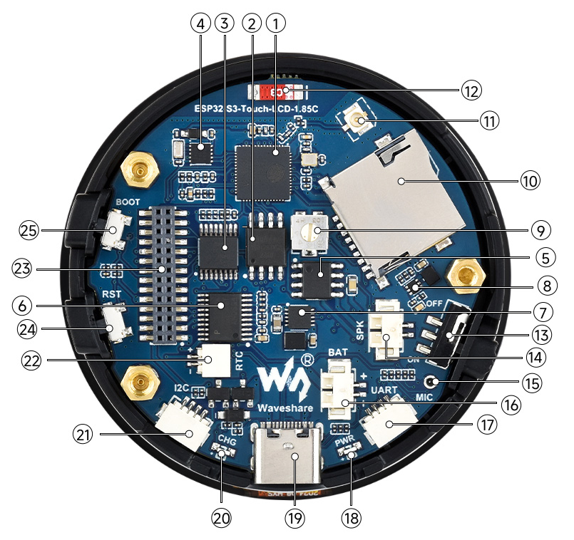
1. ESP32-S3R8 2. 16MB Flash 3. TCA9554PWR 4. RTC clock chip 5. Amplifier chip 6. PCM5101 audio decoding chip 7. Battery recharge manager Chip 8. MP1605GTF-Z 9. Speaker volume button 10. TF card slot 11. IPEX Gen 1 connector 12. Patch ceramic antenna 13. System battery switch 14. Speaker interface | 15. Microphone 16. Battery header 17. UART interface 18. Power indicator 19. USB Type-C interface 20. Charge indicator 21. I2C interface 22. RTC battery header 23. 1.27mm socket interface 24. RESET button 25. BOOT button |
Interfaces
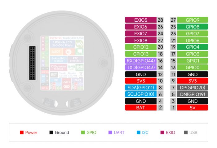
- I2C interface
| Pin | Function | Description |
| GND | GND | Ground |
| 3V3 | 3V3 | External output 3.3V |
| SCL | SCL (GPIO10) | I2C clock pin, cannot be used as regular GPIO |
| SDA | SDA (GPIO11) | I2C data pin, cannot be used as regular GPIO |
- UART interface
| Pin | Function | Description |
| GND | GND | Ground |
| 3V3 | 3V3 | External output 3.3V |
| TXD | TXD (GPIO43) | UART transmit data or as regular GPIO |
| RXD | RXD (GPIO44) | UART receive data or as regular GPIO |
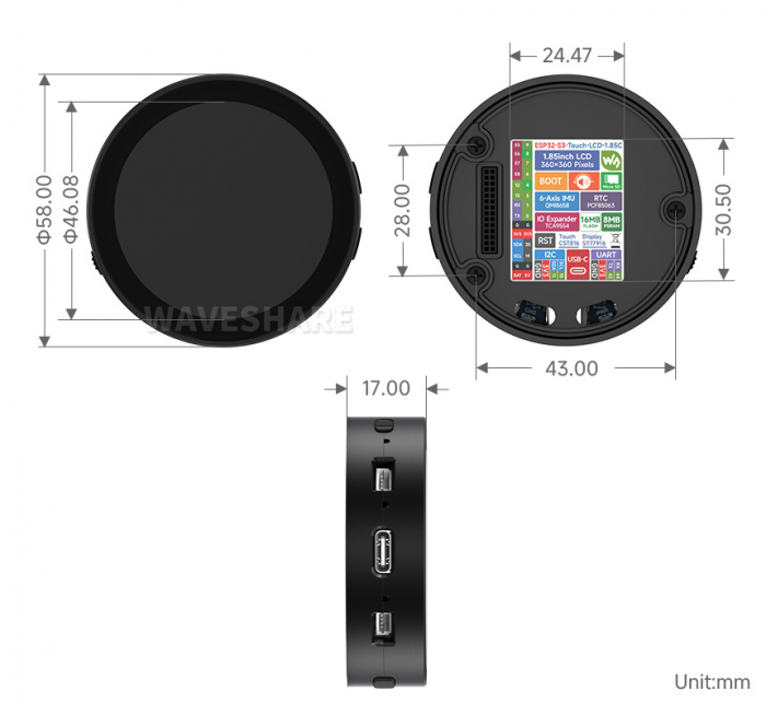
Dimensions
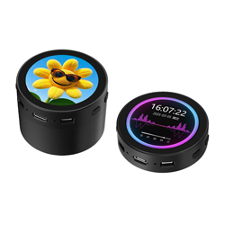
- Standard version
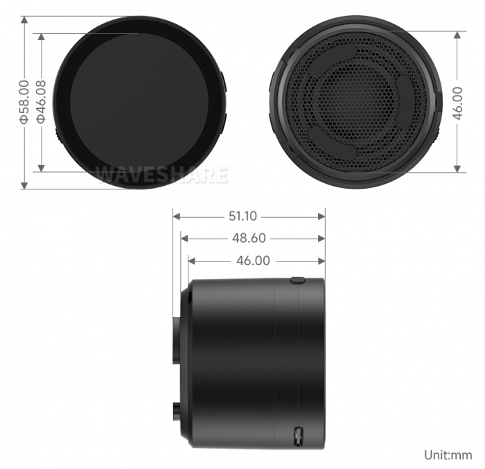
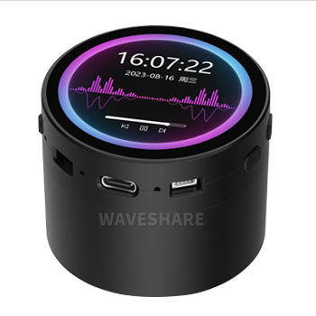
- With speaker box version, optional for 3.7V Lithium battery
Specifications
| Parameter Name | Parameter |
| Interface | USB Type-C |
| Controller chip | ESP32-S3 |
| LCD type | TFT |
| LCD controller chip | Display: ST77916 |
| Touch: CST816 | |
| Onboard devices | RTC clock: PCF85063 |
| PCM audio decoding chip: PCM5101 | |
| MIC | |
| TF | |
| Battery recharging manager module | |
| Dimensions | 58.0(R)x 17.0(H) mm 58.0(R)x 51.1(H) mm |
Internal Hardware Connection
- LCD
| LCD Pin | ESP32S3 |
| LCD_SDA0 | GPIO46 |
| LCD_SDA1 | GPIO45 |
| LCD_SDA2 | GPIO42 |
| LCD_SDA3 | GPIO41 |
| LCD_SCK | GPIO40 |
| LCD_CS | GPIO21 |
| LCD_TE | GPIO18 |
| LCD_RST | EXIO2 |
| LCD_BL | GPIO5 |
| TP_SDA | GPIO11 |
| TP_SCL | GPIO10 |
| TP_INT | GPIO4 |
| TP_RST | EXIO1 |
- TF Card
| TF Card | ESP32S3 |
| SD_D0 / MISO | GPIO16 |
| SD_CMD / MOSI | GPIO17 |
| SD_SCK / SCLK | GPIO14 |
| SD_D3 / CS | EXIO3 |
| SD_D1 | NC |
| SD_D2 | NC |
- RTC
| PCF85063ATL | ESP32S3 |
| RTC_SCL | GPIO10 |
| RTC_SDA | GPIO11 |
| RTC_INT | EXIO4 |
- MIC
| Buzzer | ESP32S3 |
| MIC_WS | GPIO2 |
| MIC_SCK | GPIO15 |
| MIC_SD | GPIO39 |
- SPEAKER
| PCM5101 | ESP32S3 |
| Speak_DIN | GPIO47 |
| Speak_LRCK | GPIO38 |
| Speak_BCK | GPIO48 |
Version Description
|
| |
| ESP32-S3-Touch-LCD-1.85C Standard verson | ESP32-S3-Touch-LCD-1.85C-BOX With speaker box version, optional for 3.7V Lithium battery |
Assembly Video for Lithium Battery Version
Click here to view: ESP32-S3-Touch-LCD-1.85C-BOX Assembly video
Usage Instructions
ESP32-S3-Touch-LCD-1.85C currently provides two development tools and frameworks, Arduino IDE and ESP-IDF, providing flexible development options, you can choose the right development tool according to your project needs and personal habits.
Development Tools
| Arduino IDEArduino IDE is an open source electronic prototyping platform, convenient and flexible, easy to get started. After a simple learning, you can start to develop quickly. At the same time, Arduino has a large global user community, providing an abundance of open source code, project examples and tutorials, as well as rich library resources, encapsulating complex functions, allowing developers to quickly implement various functions. |
| ESP-IDFESP-IDF, or full name Espressif IDE, is a professional development framework introduced by Espressif Technology for the ESP series chips. It is developed using the C language, including a compiler, debugger, and flashing tool, etc., and can be developed via the command lines or through an integrated development environment (such as Visual Studio Code with the Espressif IDF plugin). The plugin offers features such as code navigation, project management, and debugging, etc. |

Each of these two development approaches has its own advantages, and developers can choose according to their needs and skill levels. Arduino are suitable for beginners and non-professionals because they are easy to learn and quick to get started. ESP-IDF is a better choice for developers with a professional background or high performance requirements, as it provides more advanced development tools and greater control capabilities for the development of complex projects.
Components Preparation
- ESP32-S3-Touch-LCD-1.85C x1
- TF card with MP3 files x1
- USB cable (Type A male to Type C male) x 1
Precautions
- Please note that the computer username must be in English, the username in Chinese will lead to compilation errors
- If you want to continue using the onboard Bluetooth device when enabling all onboard devices with the example provided, it is recommended to use a different audio library file with a small memory footprint (otherwise it will result in a large SRAM footprint)
- The development board uses USB to download the demo. If the port cannot be recognized, please enter boot mode (press and hold the boot button, then connect to the computer, and then release the boot button). After downloading the demo, press the RESET button to run the demo.
- The ESP32 3.0.2 on Arduino is developed based on ESP-IDF v5.1, which is quite different from the previous version based on ESP-IDF V4.X. After the following operations, programs that could run normally on version 2.0.x may require some adjustments to function properly.
Working with Arduino
This chapter introduces setting up the Arduino environment, including the Arduino IDE, management of ESP32 boards, installation of related libraries, program compilation and downloading, as well as testing demos. It aims to help users master the development board and facilitate secondary development.
Environment Setup
Download and Install Arduino IDE
- Click to visit the Arduino official website, select the corresponding system and system bit to download
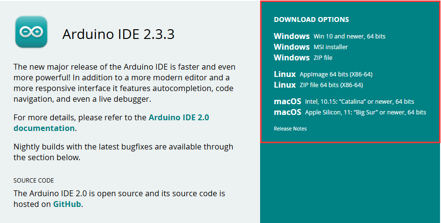
- Run the installer and install all by default
Install ESP32 Development Board
- Before using ESP32-related motherboards with the Arduino IDE, you must first install the software package for the esp32 by Espressif Systems development board
- According to board installation requirement, it is generally recommended to use Install Online. If online installation fails, use Install Offline.
- For the installation tutorial, please refer to Arduino board manager tutorial
| Board name | Board installation requirement | Version number requirement |
|---|---|---|
| esp32 by Espressif Systems | "Install Offline" / "Install Online” | 3.0.2 and above |
Install Library
- When installing Arduino libraries, there are usually two ways to choose from: Install online and Install offline. If the library installation requires offline installation, you must use the provided library file
For most libraries, users can easily search and install them through the online library manager of the Arduino software. However, some open-source libraries or custom libraries are not synchronized to the Arduino Library Manager, so they cannot be acquired through online searches. In this case, users can only manually install these libraries offline. - For library installation tutorial, please refer to Arduino library manager tutorial
- ESP32-S3-Touch-LCD-1.85C library files are stored in the demo at the following path:
..\ESP32-S3-Touch-LCD-1.85C-Demo\Arduino\libraries
| Library Name | Description | Version | Library Installation Requirement |
|---|---|---|---|
| LVGL | Graphical library | v8.3.10 | "Install Offline" |
| ESP32-audioI2S-master | Audio decoding library | v2.0.0 | "Install Offline" |
Run the First Arduino Demo
New Project
- Run the Arduino IDE and select
File->New Sketch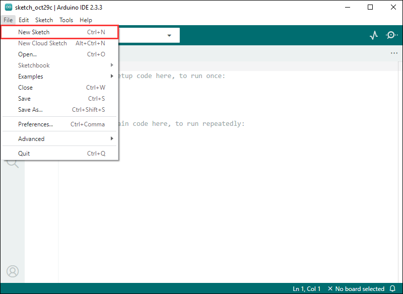
- Enter the code:
void setup() {
  // put your setup code here, to run once:
  Serial.begin(115200);
}

void loop() {
  // put your main code here, to run repeatedly:
  Serial.println("Hello, World!");
  delay(2000);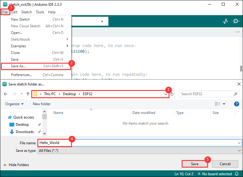
}- Save the project and select
File->Save As.... In the pop-up menu, select the path to save the project, and enter a project name, such as Hello_World, clickSave
Compile and Flash Demos
- Select the corresponding development board, take the ESP32S3 motherboard as an example:
①. Click to select the dropdown menu option Select Other Board and Port;
②. Search for the required development board model esp32s3 dev module and select;
③. Select COM Port;
④. Save the selection.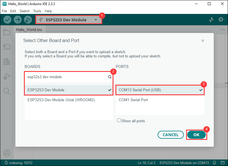
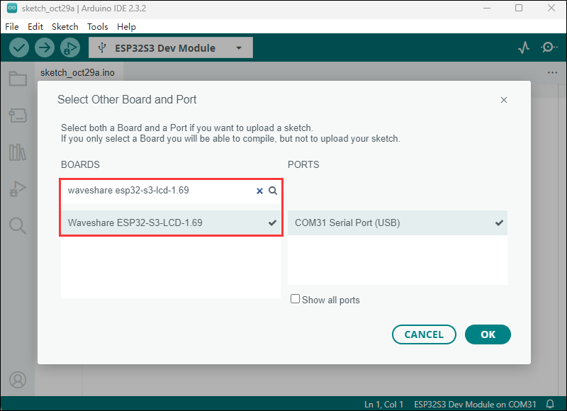
- Some development boards with specified version numbers support direct model selection, for example, "Waveshare ESP32-S3-LCD-1.69":
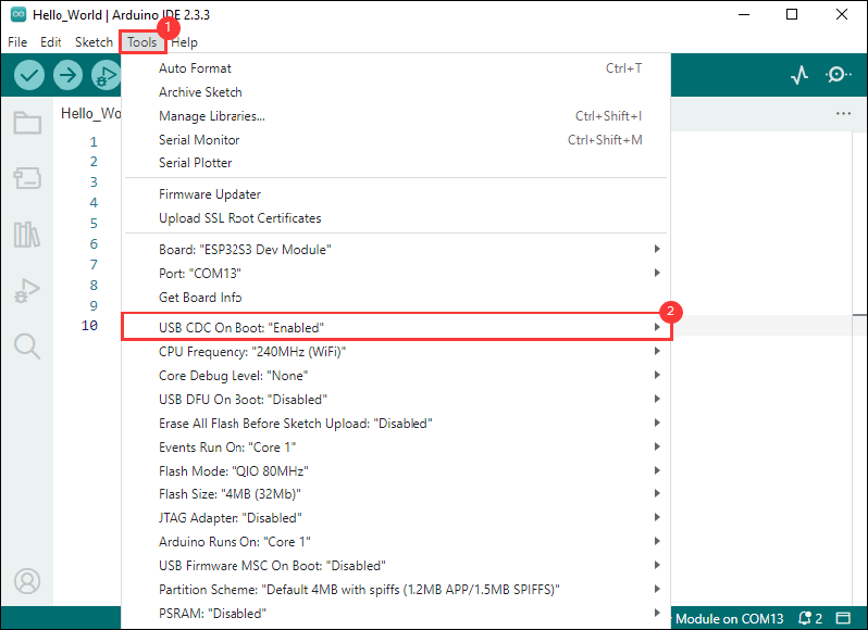
- If the ESP32S3 mainboard only has a USB port, you need to enable USB CDC, as shown in the following diagram:
- Compile and upload the program:
①. Compile the program; ②. Compile and download the program; ③. Download successful.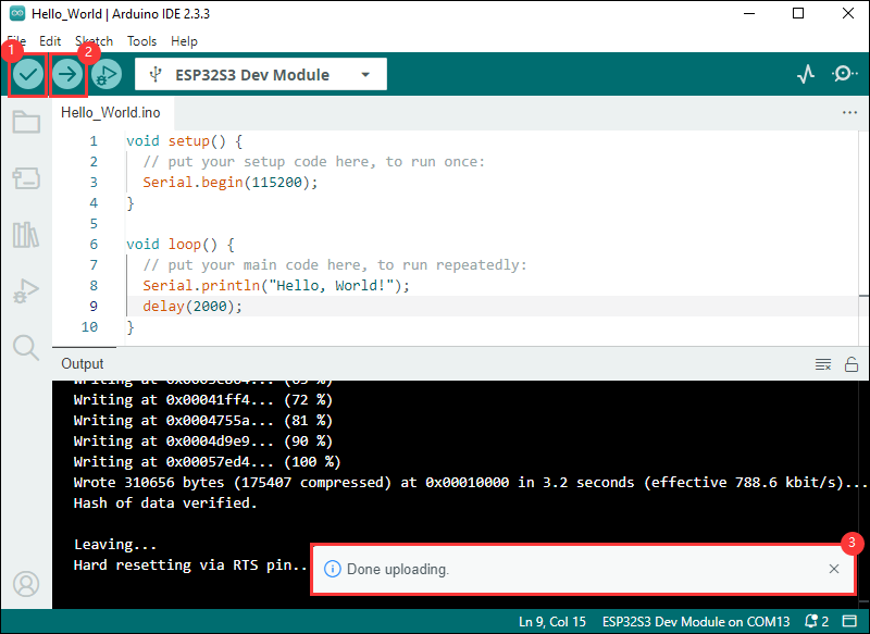
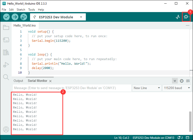
- Open the Serial Monitor window, and the demo will print "Hello World!" every 2 seconds, and the operation is as follows:
Demo

| Demo | Basic Description | Dependency Library |
|---|---|---|
| LVGL_Arduino | Test onboard device functionality | LVGL, ESP32-audioI2S-master |
Arduino Project Parameter Setting
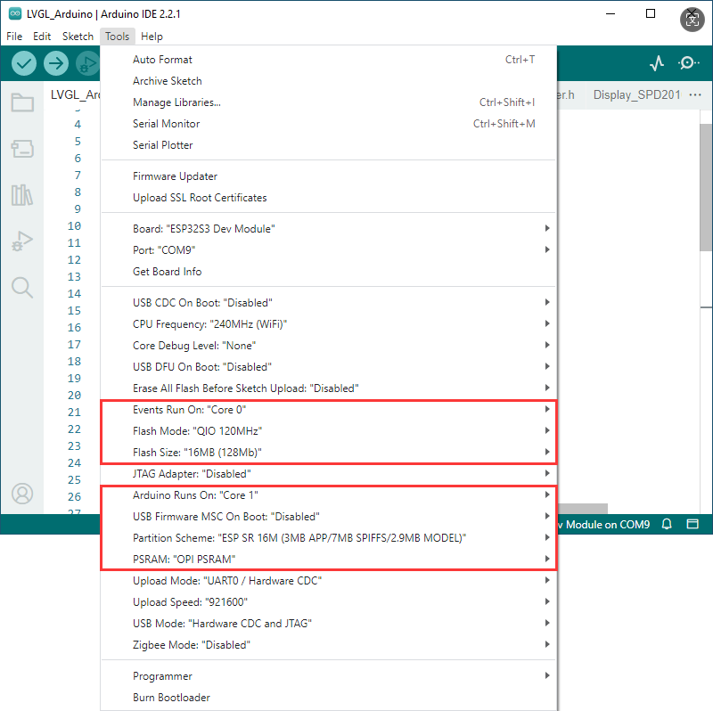
- If the flashed demo has a speech recognition model, then select "ESP SR 16M (3MB APP/7MB SPIFFS/2.9MB MODEL)" for Partition Scheme
- If the flashed demo doesn't have a speech recognition model, then select "16M Flash (3MB APP/9.9MB FATFS)" or other for Partition Scheme
LVGL_Arduino
Demo description
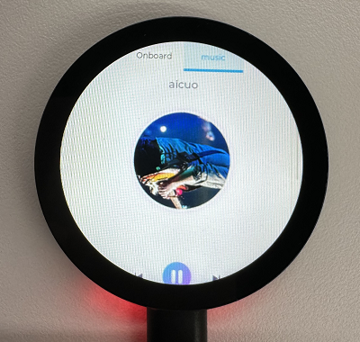
- This example demonstrates the functions of each device on the board, page 1 displays SD Card, Flash Size, Battery Voltage and other parameters, and page 2 shows the music playback interface; In addition, speech recognition is added to this demo.
Hardware connection
- Insert the TF card into the development board (can be used without a TF card)
- Connect the development board to the computer
Code analysis
- setup(): Initialize hardware, configure peripherals, etc.
- Hardware initialization:
setup()internally executes multiple initialization functions to configure and initialize hardware components connected to Arduino, such as RTC, LCD display, TF card, audio module, microphone, etc. With these initializations, it is ensured that the hardware is working properly - Graphics interface initialization: Call
Lvgl_Init()to initialize LVGL (Light and Versatile Graphics Library), a widely used graphics library for embedded systems.Lvgl_Example1()is a demo that shows how to render a graphical interface on a display - Task scheduling:
Driver_Loop()function creates a task (DriverTask) that manages and loops some peripheral operations
- Hardware initialization:
- loop(): Mainly used for GUI updates and task scheduling
- LVGL task loop:
Lvgl_Loop()is a loop function of the LVGL library that handles graphical interface updates, event responses, and other UI-related operations. In embedded systems, graphics libraries often need to be called frequently in the main loop to keep the interface refreshed and the interaction real-time - Task scheduling control:
vTaskDelay(pdMS_TO_TICKS(5))is used to pause the task for 5 milliseconds.vTaskDelayis a delay function in FreeRTOS that aims to reduce CPU usage, avoid taking up too much time slice, and ensure that other tasks of the system, such as peripheral processing, can be performed on time
- LVGL task loop:
Result demonstration
- LCD screen display


- LCD screen display parameter description
| Parameter | Function | Description |
| SD Card | Display TF card size | Connect the TF card, if the recognition fails, please format the TF card to FAT32 format (please wait for a while to reset and check again if the recognition fails for the first time) |
| Flash Size | Display Flash size | Current onboard 16MB Flash |
| Battery Voltage | Battery voltage | The battery voltage can be detected when the battery is connected |
| RTC Time | Display RTC time | Display current RTC time If the RTC time is not consistent with the current time, because the data cannot be retained in the power-off state, if you need to keep the RTC time normal, you need to connect the RTC battery and update the RTC time |
| Wireless scan | Display the number of scanned WiFi | When it finishes, display Scan Finish at the end |
| Backlight brightness | Brightness slider | Adjust screen brightness |
- Page 2 is the UI page for playing mp3 audio in the root directory of the TF card
- This program enables speech recognition by default, the wake-up word is "hi esp", after waking up, you can speak the command after the backlight is dimmed (if the backlight is not dimmed, it means that it has not been woken up, the recognition requirements are strict, the pronunciation needs to be standard, and the speech speed is slowed down)
- The following are available in several formats of MIC test audio (Please note that every time the hi esp wake-up fails, please reset the audio to the playback location of the wake-up word and replay it)
- Please do not perform speech recognition when using the speaker to play audio
- The reason the wake-up word plays twice in the test audio is due to the current firmware version's initial wake-up requiring the device to be focused (an analogy), and the current firmware does not permit the disabling of this function
// Commands
Turn on the backlight
Turn off the backlight
Backlight is brightest
Backlight is darkest
Switch to Chinese/English recognition model
The initial environment setting is for English recognition, and you can switch to Chinese recognition model or back to English recognition model by following these steps
Switch to Chinese recognition model
Chinese recognition environment setup
- Download the provided demo file Demo using Chinese model
- Enter the path C:\Users\Waveshare\AppData\Local\Arduino15\packages\esp32\hardware\esp32\3.0.2\libraries\ESP_SR\src (Waveshare is the computer username)
- Replace the esp32-hal-sr.c in this path with the downloaded file
- Download the Chinese model Chinese model - wake-up word hi 乐鑫
- Enter the path C:\Users\Waveshare\AppData\Local\Arduino15\packages\esp32\tools\esp32-arduino-libs\idf-release_v5.1-bd2b9390ef\esp32s3\esp_sr (Waveshare is the computer username)
- Replace the srmodels.bin in this path with the downloaded file
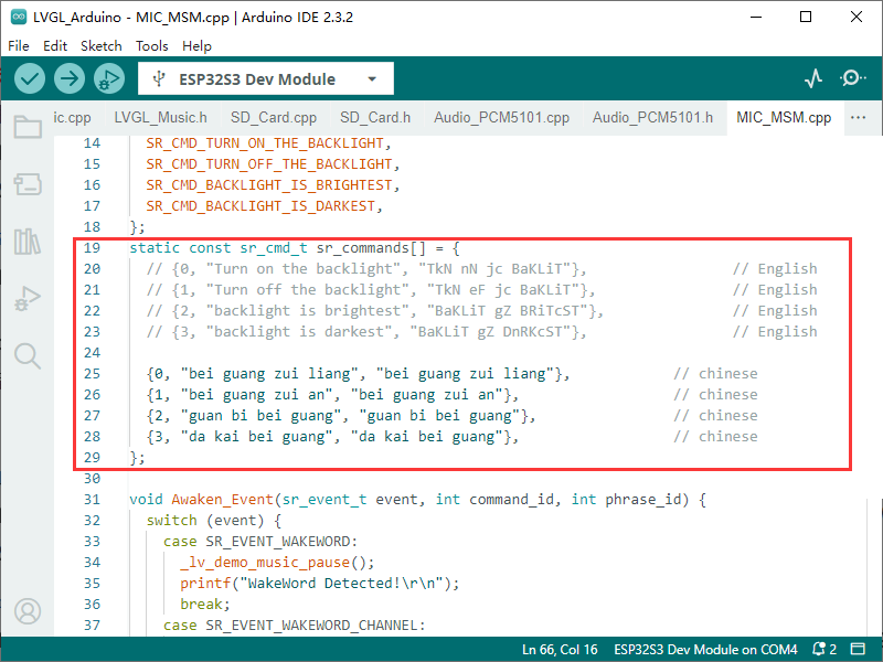
- Modify the recognition command in the demo to Chinese command (Pinyin)
Switch to English recognition model
English recognition environment setup
- The initial state of the environment is the English recognition environment by default, and if it is not converted to Chinese, the following modifications are not made
- If it has been previously modified to Chinese recognition, download the provided demo file Demo using English model
- Enter the path C:\Users\Waveshare\AppData\Local\Arduino15\packages\esp32\hardware\esp32\3.0.2\libraries\ESP_SR\src (Waveshare is the computer username)
- Replace the esp32-hal-sr.c in this path with the downloaded file
- Download the English model English model - wake-up word hi esp
- Enter the path C:\Users\Waveshare\AppData\Local\Arduino15\packages\esp32\tools\esp32-arduino-libs\idf-release_v5.1-bd2b9390ef\esp32s3\esp_sr (Waveshare is the computer username)
- Replace the srmodels.bin in this path with the downloaded file
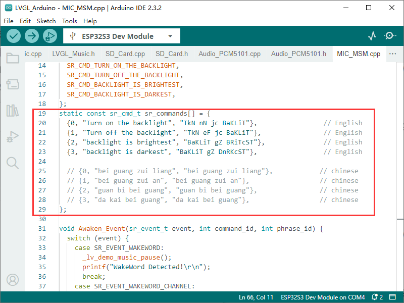
- Modify the recognition command in the demo to English command (phonemes)
Working with ESP-IDF
This chapter introduces setting up the ESP-IDF environment setup, including the installation of Visual Studio and the Espressif IDF plugin, program compilation, downloading, and testing of demos, to assist users in mastering the development board and facilitating secondary development. 
Environment Setup
Download and Install Visual Studio
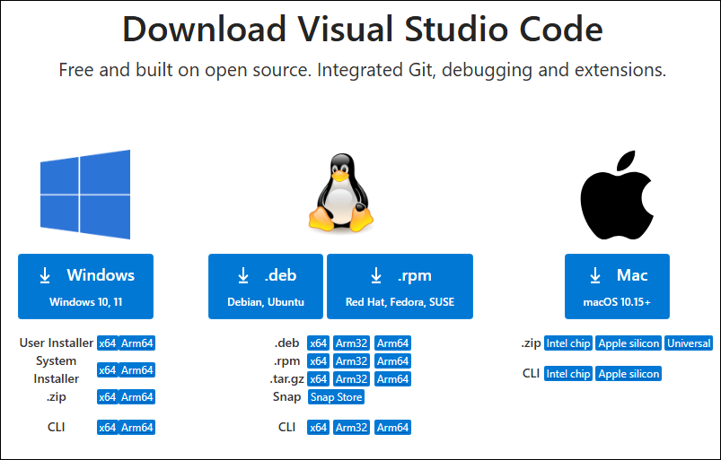
- Open the download page of VScode official website, choose the corresponding system and system bit to download
- After running the installation package, the rest can be installed by default, but here for the subsequent experience, it is recommended to check boxes 1, 2, and 3
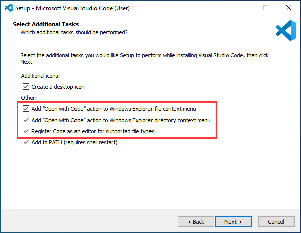
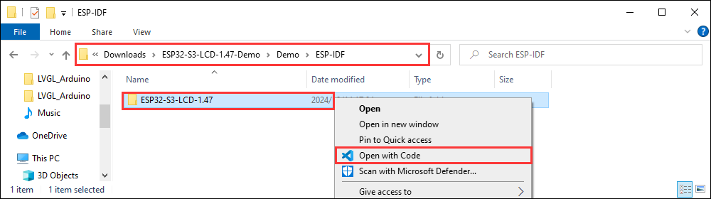
- After the first two items are enabled, you can open VSCode directly by right-clicking files or directories, which can improve the subsequent user experience.
- After the third item is enabled, you can select VSCode directly when you choose how to open it
Install Espressif IDF Plugin
- It is generally recommended to use Install Online. If online installation fails due to network factor, use Install OIffline
- For more information about how to install the Espressif IDF plugin, see Install Espressif IDF Plugin
| Plugin name | Plugin installation requirement | Version number requirement |
|---|---|---|
| Espressif IDF | "Install Offline" / "Install Online” | ≥5.3.1 |
Run the First ESP-IDF Demo
New Project
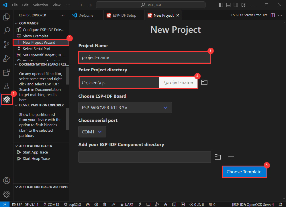
Create Demo
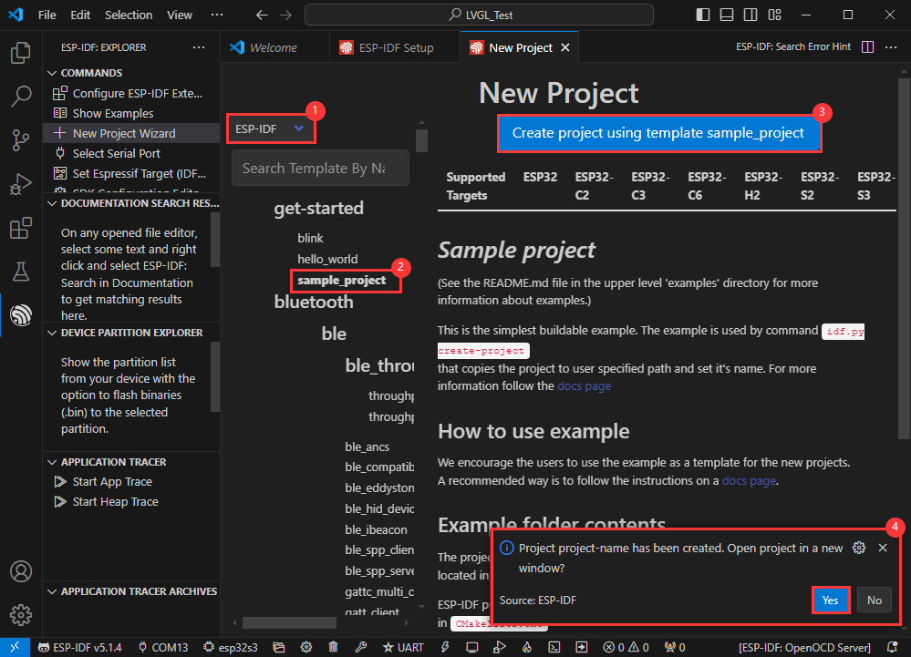
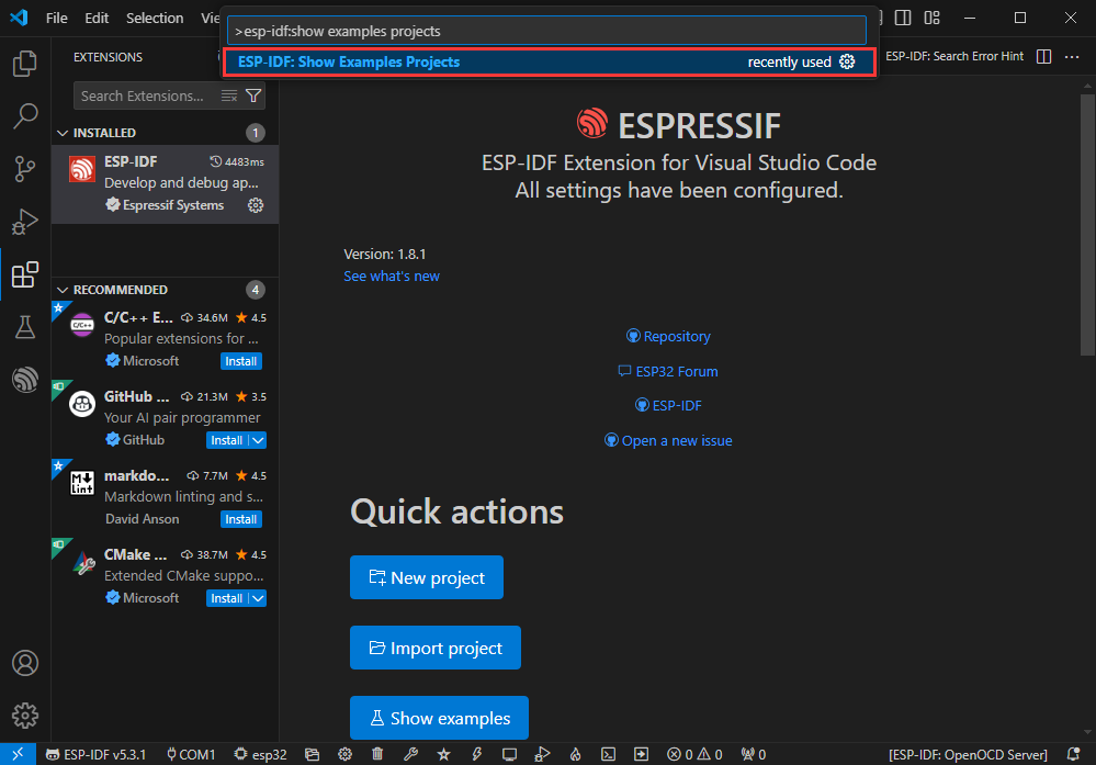
- Using the shortcut F1, enter esp-idf:show examples projects
- Select your current IDF version
- Take the Hello world demo as an example
①Select the corresponding demo
②Its readme will state what chip the demo applies to (how to use the demo and the file structure are described below, omitted here)
③Click to create the demo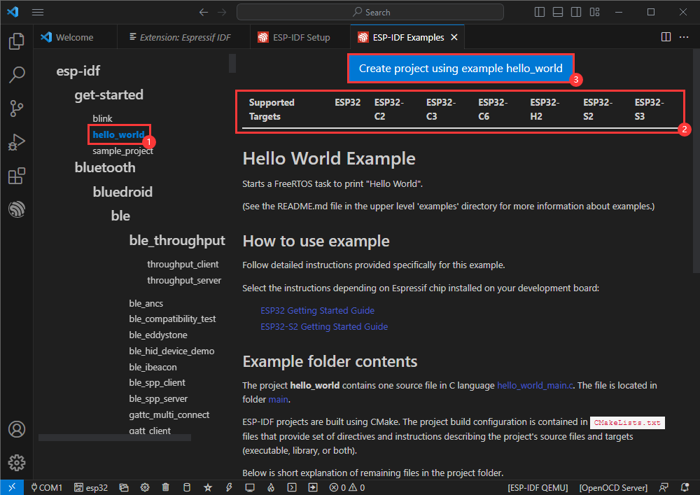
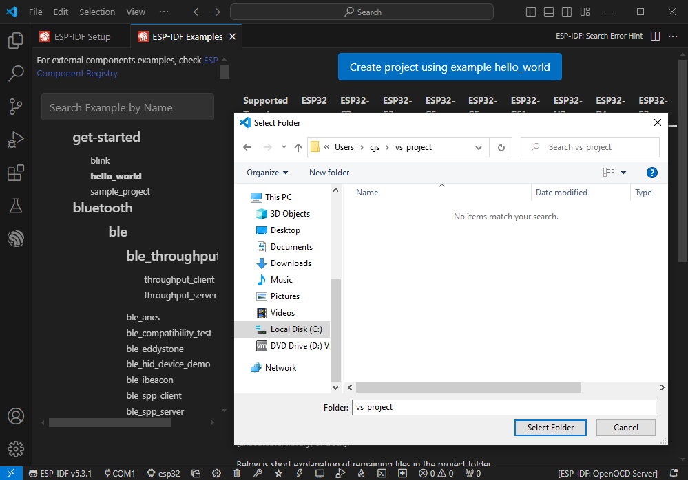
- Select the path to save the demo, and require that the demos cannot use folders with the same name
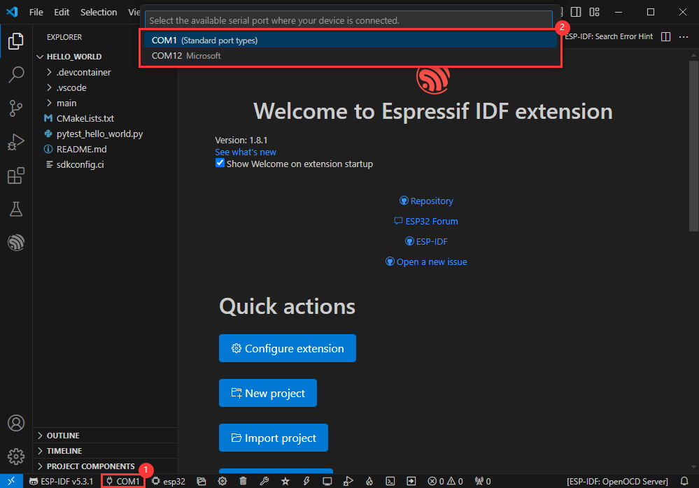
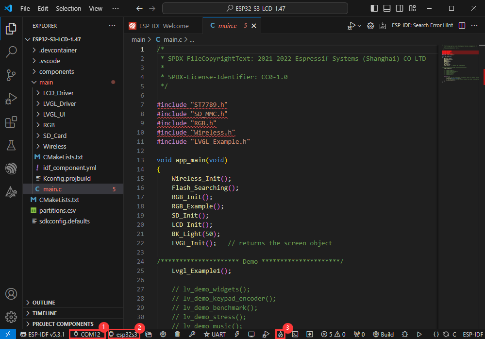
Modify COM Port
- The corresponding COM ports are shown here, click to modify them
- Please select the COM ports according to your device (You can view it from the device manager)
- In case of a download failure, please press the Reset button for more than 1 second or enter download mode, and wait for the PC to recognize the device again before downloading once more
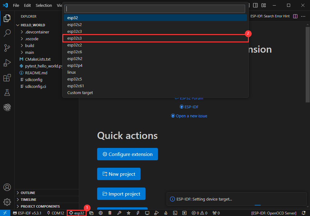
Modify Driver Object
- Select the object we need to drive, which is our main chip ESP32S3
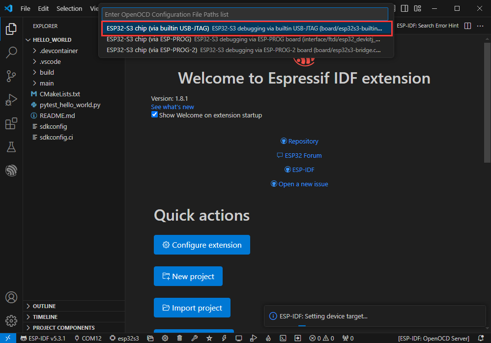
- Choose the path to openocd, it doesn't affect us here, so let's just choose one
Other Status Bar Functions
①.ESP-IDF Development Environment Version Manager, when our project requires differentiation of development environment versions, it can be managed by installing different versions of ESP-IDF. When the project uses a specific version, it can be switched to by utilizing it
②.Device flashing COM port, select to flash the compiled program into the chip
③.Select set-target chip model, select the corresponding chip model, for example, ESP32-P4-NANO needs to choose esp32p4 as the target chip
④.menuconfig, click it to Modify sdkconfig configuration file Project configuration details
⑤.fullclean button, when the project compilation error or other operations pollute the compiled content, you can clean up all the compiled content by clicking it
⑥.Build project, when a project satisfies the build, click this button to compile
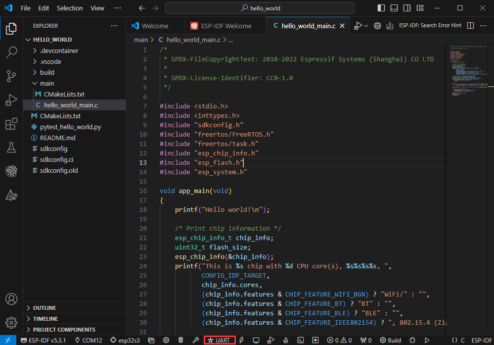
⑦.Current download mode, the default is UART
⑧.flash button, when a project build is completed, select the COM port of the corresponding development board, and click this button to flash the compiled firmware to the chip
⑨.monitor enable flashing port monitoring, when a project passes through Build --> Flash, click this button to view the log of output from flashing port and debugging port, so as to observe whether the application works normally
⑩.Debug
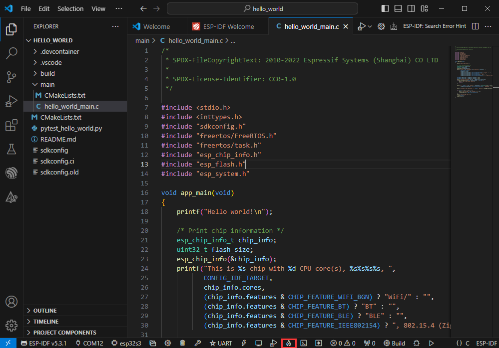
⑪.Build Flash Monitor one-click button, which is used to continuously execute Build --> Flash --> Monitor, often referred to as "little flame"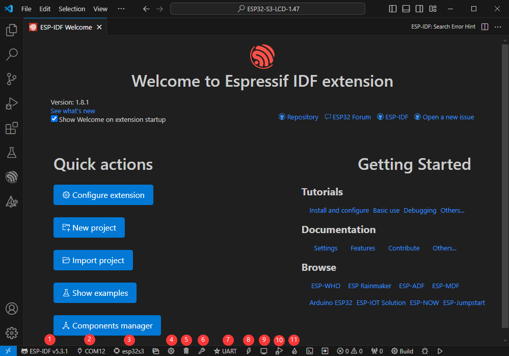
Compile, Flash and Serial Port Monitor
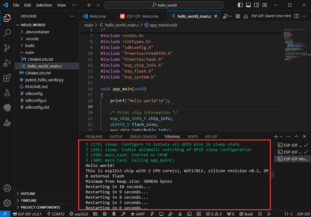
- Click on the all-in-one button we described before to compile, flash and open the serial port monitor
- It may take a long time to compile especially for the first time
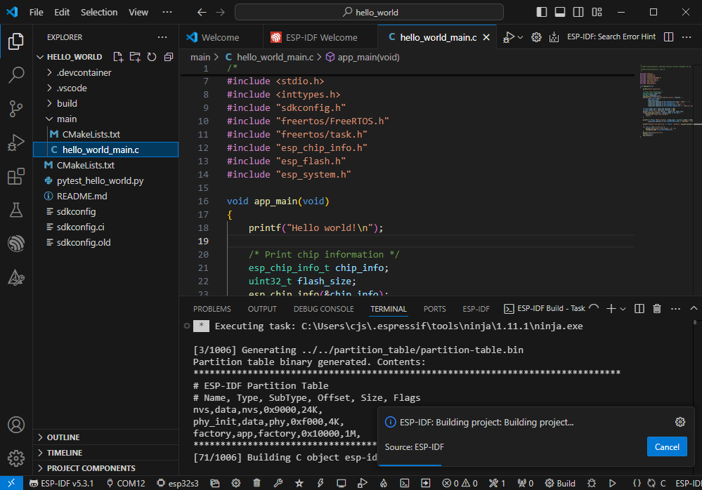
- During this process, the ESP-IDF may take up a lot of CPU resources, so it may cause the system to lag
- If it is the first time to flash the program for a new project, you will need to select the download method, and select UART
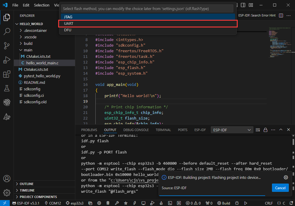
- This can also be changed later in the Download methods section (click on it to pop up the options)
- As it comes with the onboard automatic download circuit, it can be downloaded automatically without manual operation
- After successful download, it will automatically enter the serial monitor, you can see the chip output the corresponding information and be prompted to restart after 10S
Use the IDF Demos
Open In the Software
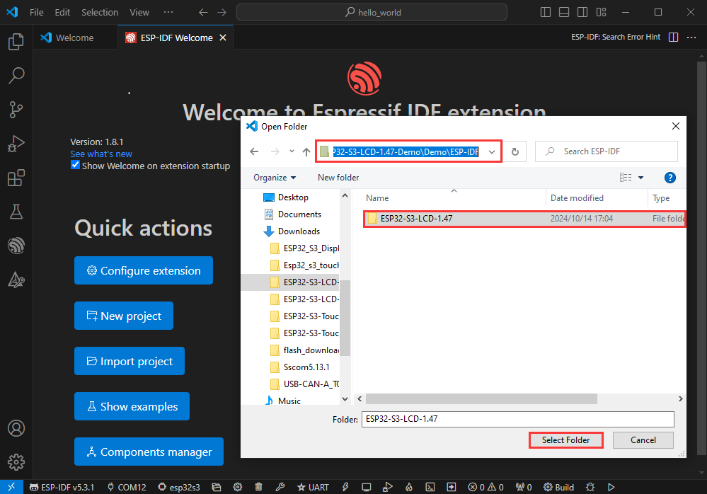
- Open VScode software and select the folder to open the demo
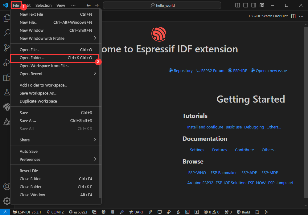
- Select the provided ESP-IDF example and click to select the file (located in the /Demo/ESP-IDF path under demo)
Open from Outside the Software
- Select the project directory correctly and open the project, otherwise it will affect the compilation and flashing of subsequent programs
- After connecting the device, select the COM port and model, click below to compile and flash to achieve program control
ESP-IDF Project Details
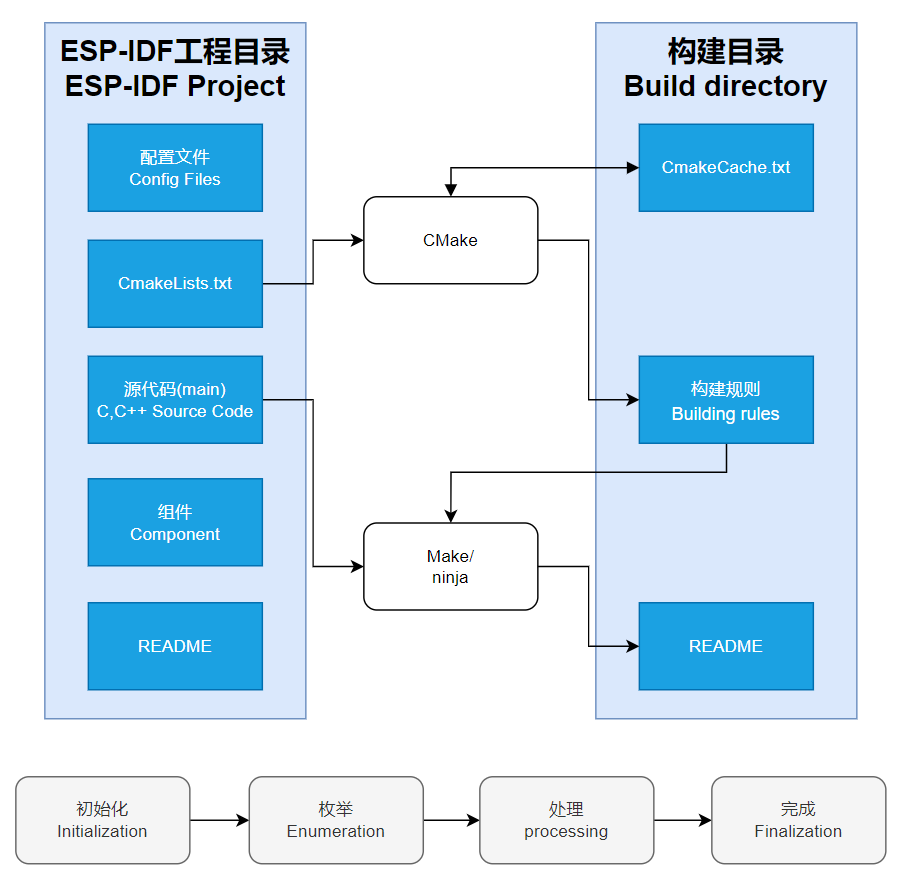
- Component: The components in ESP-IDF are the basic modules for building applications, each component is usually a relatively independent code base or library, which can implement specific functions or services, and can be reused by applications or other components, similar to the definition of libraries in Python development.
- Component reference: The import of libraries in the Python development environment only requires to "import library name or path", while ESP-IDF is based on the C language, and the importing of libraries is configured and defined through
CMakeLists.txt. - The purpose of CmakeLists.txt: When compiling ESP-IDF, the build tool
CMakefirst reads the content of the top-levelCMakeLists.txtin the project directory to read the build rules and identify the content to be compiled. When the required components and demos are imported into theCMakeLists.txt, the compilation toolCMakewill import each content that needs to be compiled according to the index. The compilation process is as follows:
- Component reference: The import of libraries in the Python development environment only requires to "import library name or path", while ESP-IDF is based on the C language, and the importing of libraries is configured and defined through
Demo

| Demo | Basic Description |
|---|---|
| ESP32-S3-Touch-LCD-1.85C-Test | Test onboard device functionality |
ESP32-S3-Touch-LCD-1.85C-Test
Demo description
- This example demonstrates the functions of each device on the board, page 1 displays SD Card, Flash Size, Battery Voltage and other parameters, and page 2 shows the music playback interface; In addition, speech recognition is added to this demo.
Hardware connection
- Insert the TF card into the development board (can be used without a TF card)
- Connect the development board to the computer
Code analysis
- Driver_Init(): Initializes the resources required by the hardware, driver, and system, and creates a task to cycle through the hardware driver
- Hardware initialization:
Driver_Init()is responsible for initializing multiple hardware modules, such as power management, clock, I2C bus, external I/O, sensors, etc. - Task creation:
xTaskCreatePinnedToCore()creates a FreeRTOS taskDriver_Loopand binds it to Core 0. This means that theDriver_Loopfunction will be executed in a loop, handling the hardware-related operations. This task will run concurrently with other tasks, contributing to the real-time performance of the hardware driver - Modular design: The initialization function disperses the initialization of each hardware into different modules, which is easy to maintain and expand. If there's new hardware that needs to be supported, just add the initialization code here
- Hardware initialization:
- Driver_Loop(): This function runs in a loop in a FreeRTOS task, periodically performing the work of each hardware driver. It is the core component of most hardware driver operations
- Loop execution hardware driver: Call multiple hardware driver functions in a loop within the
Driver_Loop()function, such asQMI8658_Loop(),PCF85063_Loop(),BAT_Get_Volts()andPWR_Loop(), these are hardware operations that are performed in real timeQMI8658_Loop(): Handles interaction with QMI8658 sensor and reads sensor dataPCF85063_Loop(): Handles PCF85063 clock module and updates the timeBAT_Get_Volts(): Gets the current battery voltage to ensure that the device battery level meets the requirementsPWR_Loop(): Performs power management tasks, monitors power supply status, and controls power on or off
- Scheduled task: Using
vTaskDelay(pdMS_TO_TICKS(100)), theDriver_Loop()function delays once every 100 milliseconds. This helps ensure that the task does not consume excessive CPU resources and avoids too frequent operations on hardware - Delete task:
vTaskDelete(NULL)is used to delete the current task, but sincewhile(1)is an infinite loop, the actual line of code will never be executed
- Loop execution hardware driver: Call multiple hardware driver functions in a loop within the
Result demonstration
- LCD screen display
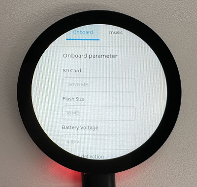
- LCD screen display parameter description
| Parameter | Function | Description |
| SD Card | Display TF card size | Connect the TF card, if the recognition fails, please format the TF card to FAT32 format (please wait for a while to reset and check again if the recognition fails for the first time) |
| Flash Size | Display Flash size | Current onboard 16MB Flash |
| Battery Voltage | Battery voltage | The battery voltage can be detected when the battery is connected |
| RTC Time | Display RTC time | Display current RTC time If the RTC time is not consistent with the current time, because the data cannot be retained in the power-off state, if you need to keep the RTC time normal, you need to connect the RTC battery and update the RTC time |
| Wireless scan | Display the number of scanned WiFi | When it finishes, display Scan Finish at the end |
| Backlight brightness | Brightness slider | Adjust screen brightness |
- Page 2 is the UI page for playing mp3 audio in the root directory of the TF card
- This program enables speech recognition by default, the wake-up word is "hi esp", after waking up, you can speak the command after the backlight is dimmed (if the backlight is not dimmed, it means that it has not been woken up, the recognition requirements are strict, the pronunciation needs to be standard, and the speech speed is slowed down)
- The following are available in several formats of MIC test audio (Please note that every time the hi esp wake-up fails, please reset the audio to the playback location of the wake-up word and replay it)
- Please do not perform speech recognition when using the speaker to play audio
- The reason the wake-up word plays twice in the test audio is due to the current firmware version's initial wake-up requiring the device to be focused (an analogy), and the current firmware does not permit the disabling of this function
// Commands
Turn on the backlight
Turn off the backlight
Backlight is brightest
Backlight is darkest
Switch to Chinese/English recognition model
The initial environment setting is for English recognition, and you can switch to Chinese recognition model or back to English recognition model by following these steps
Switch to Chinese/English recognition model
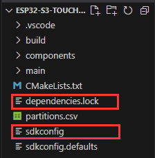
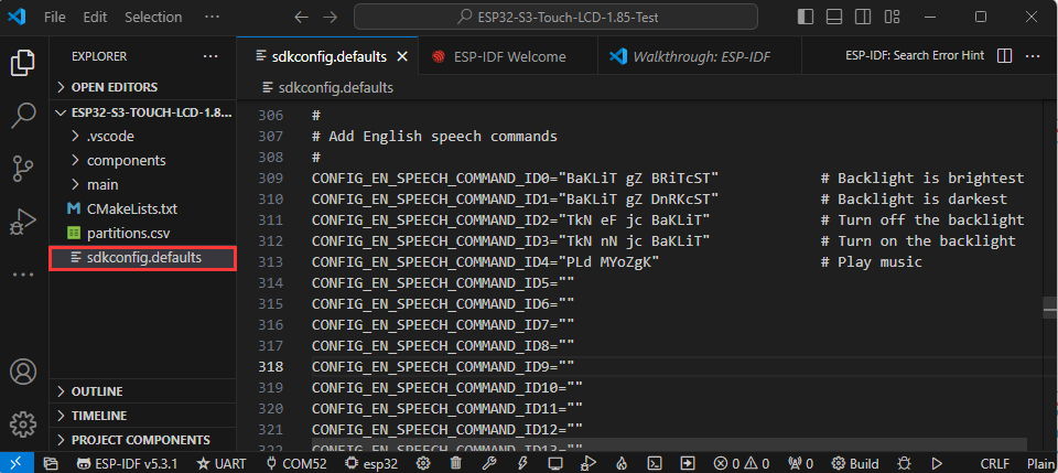
- If the following two files exist in the project, delete these two files
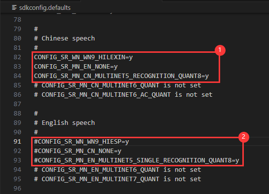
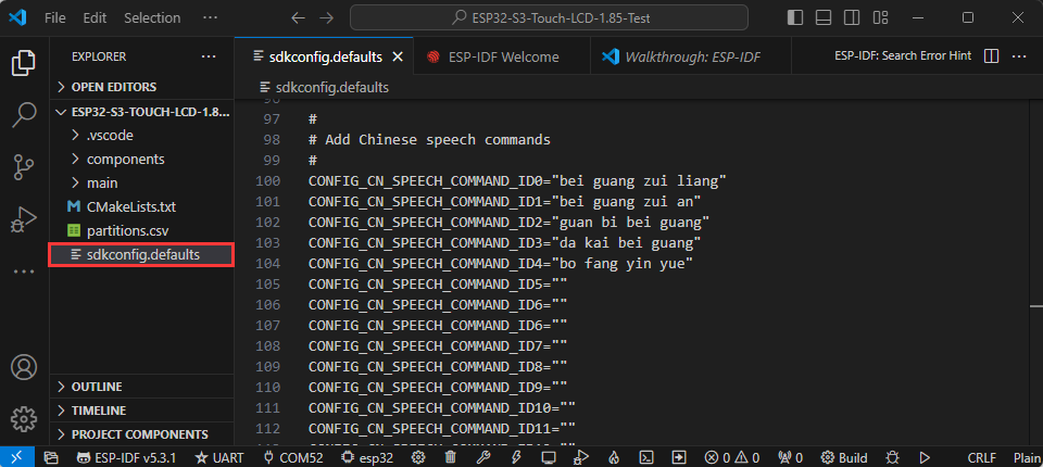
- Enter the file sdkconfig.defaults, find here.
- Use the "#" comment ① to switch to the English recognition model
- Use the "#" comment ② to switch to the Chinese recognition model
- Use the "#" comment ① to switch to the English recognition model
Generate Speech Control Command
Environment Preparation
- Check if your computer has a Python environment
- Open the command line: win+r -> enter cmd
①.Enter python --version and the python version number appears, which means that it is installed
②.Type where python to see where python is installed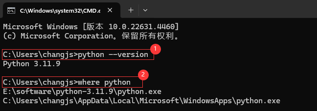
The Python environment under the C drive is the Python environment that is automatically installed when VS Code is installed;
The disk E contains the Python environment used in the following steps;
- On the command line, enter pip install g2p_en to install the g2p_en package
- Install the resource package in the corresponding user's C:\Users\username\AppData\Roaming directory, and double-click to extract the file
- On the command line, enter pip install pypinyin to install the pypinyin library
Generate Chinese Pinyin
- Download the Chinese command generation file
- Command line switch path to Chinese command generation folder (the path varies from person to person, the following is only for reference)
cd /d E:\download\Generate_Chinese_command
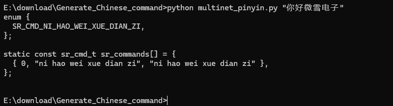
- Execute the command line multinet_pinyin.py to generate Chinese pinyin
python multinet_pinyin.py "Chinese to be converted to Pinyin"
Example: Python multinet_pinyin.py "你好微雪电子"
Generate English phonemes
- Download the English command generation file
- Command line switch path to English command generation folder (the path varies from person to person, the following is only for reference)
cd /d E:\download\Generate_English_command
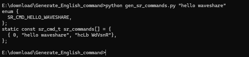
- Execute the command line gen_sr_commands.py to generate English phonemes
python gen_sr_commands.py "English to be converted to phonemes"
Example: python gen_sr_commands.py "hello waveshare”
Command modification
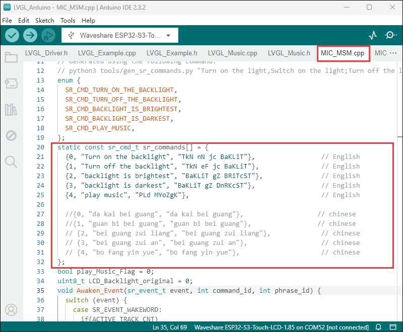
In Arduino
In ESP-IDF
- Chinese commands
- English commands
Flash Firmware Flashing and Erasing
- The current demo provides test firmware, which can be used to test whether the onboard device functions properly by directly flashing the test firmware
- bin file path:
..\ESP32-S3-Touch-LCD-1.85C-Demo\Firmware
Resources
Schematic Diagram
Demo
Datasheets
ESP32-S3
Other Components
Software Tools
Arduino
VScode
Firmware Flashing Tool
Other Resource Links
Project Resources
This section features third - party project resources. We merely provide links and bear no responsibility for content updates or maintenance. Thank you for your understanding.
Volos Projects-ESP32 MP3 Player
- Youtube: https://www.youtube.com/watch?v=ybR_GDFYIVQ
- Github: https://github.com/VolosR/mp3Waveshare185
FAQ
- Click the Reset button for more than 1 second, wait for the PC to re-recognize the device and then download again
- Long press the BOOT button, press RESET at the same time, then release RESET, then release the BOOT button, at this time the module can enter the download mode, which can solve most of the problems that can not be downloaded.
- Press and hold the BOOT button to reconnect the USB cable, and then release the BOOT button after the USB cable is connected, at this time the module can enter the download mode, which can solve most of the problems that can not be downloaded.
It may be due to Flash blank and the USB port is not stable, you can long-press the BOOT button, press RESET at the same time, and then release RESET, and then release the BOOT button, at this time the module can enter the download mode to flash the firmware (demo) to solve the situation.
- It's normal for the first compilation to be slow, just be patient
- Some AppData folders are hidden by default and can be set to show.
- English system: Explorer->View->Check "Hidden items"
- Chinese system: File Explorer -> View -> Display -> Check "Hidden Items"
- Windows system:
①View through Device Manager: Press the Windows + R keys to open the "Run" dialog box; input devmgmt.msc and press Enter to open the Device Manager; expand the "Ports (COM and LPT)" section, where all COM ports and their current statuses will be listed.
②Use the command prompt to view: Open the Command Prompt (CMD), enter the "mode" command, which will display status information for all COM ports.
③Check hardware connections: If you have already connected external devices to the COM port, the device usually occupies a port number, which can be determined by checking the connected hardware.
- Linux system:
①Use the dmesg command to view: Open the terminal.
①Use the ls command to view: Enter ls /dev/ttyS* or ls /dev/ttyUSB* to list all serial port devices.
③Use the setserial command to view: Enter setserial -g /dev/ttyS* to view the configuration information of all serial port devices.
- This situation is that the TF card is not installed or the TF card cannot be recognized. If this situation occurs, please wait for a period of time to reset the device. If it still cannot be resolved, please format the TF card to FAT32 format. If it still fails, please try a different TF card
- Install MAC Driver and flash again.
Depending on the demo you run, different demos have different refresh frame rates.
Whether you use the USB to UART tool to connect the UART pins, or enable USB CDC in Tools
Yes, it can be used simultaneously, but due to the larger memory usage of audio, the audio function cannot be turned on at the same time
MX1.25 interface 3.7V lithium battery
Use the one that corresponds to our interface and output voltage, the capacity depending on customer needs
0x15, 0x20, 0x51
- Check the schematic diagram for different development boards with Type-C interfaces, and handle the output accordingly:
- For development boards with direct USB output, printf function is supported for printing output. If you want to support output via the Serial function, you will need to enable the USB CDC On Boot feature or declare HWCDC.
- For development boards with UART to USB conversion, both printf and Serial functions are supported for printing output, and there is no need to enable USB CDC On Boot.
- Please refer to SquareLine Studio tutorial
Support
Monday-Friday (9:30-6:30) Saturday (9:30-5:30)
Email: services01@spotpear.com
[Tutorial Navigation]
- Overview
- Version Description
- Assembly Video for Lithium Battery Version
- Usage Instructions
- Working with Arduino
- Working with ESP-IDF
- Environment Setup
- Run the First ESP-IDF Demo
- New Project
- Create Demo
- Modify COM Port
- Modify Driver Object
- Other Status Bar Functions
- Compile, Flash and Serial Port Monitor
- Use the IDF Demos
- Demo
- Generate Speech Control Command
- Flash Firmware Flashing and Erasing
- Resources
- FAQ
- Question: After the module downloads the demo and re-downloads it, why sometimes it can't connect to the serial port or the flashing fails?
- Question: Why does the module keep resetting and flicker when viewed the recognition status from the device manager?
- Question: How to deal with the first compilation of the program being extremely slow?
- Question: What should I do if I can't find the AppData folder?
- Question: How do I check the COM port I use?
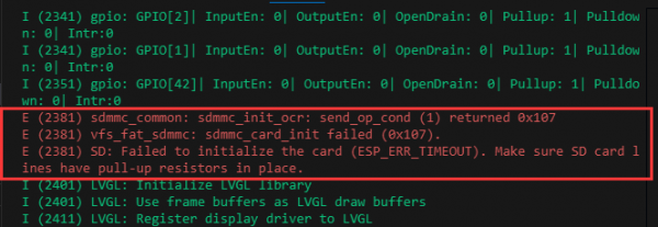
- Question: Why does ESP-IDF report this error?
- Question: Why does the program flashing fail when using a MAC device?
- Question: What is the screen refresh rate? (Frame rate)
- Question: Can this be extended to connect a camera?
- Question: When I run a program (Serial.println()) that uses a serial port, the Serial Monitor in my Arduino IDE does not show any data?
- Question: Can Wi-Fi and Bluetooth be used simultaneously?
- Question: Which battery can be used?
- Question: What capacity lithium battery is recommended?
- Question: What addresses does the I2C onboard device occupy?
- Question: Why is there no output after successfully flashing the code with no issues?
- Question: How to use SquareLine Studio to design interfaces?
- Support