- sales/support
Google Chat:---
- sales
+86-0755-88291180
- sales01
sales@spotpear.com
- sales02
dragon_manager@163.com
- support
tech-support@spotpear.com
- CEO-Complaints
zhoujie@spotpear.com
- Only Tech-Support
WhatsApp:13246739196
- Purchase/Shipping/Refund
WhatsApp:13424403025
- HOME
- >
- ARTICLES
- >
- Common Moudle
- >
- Power
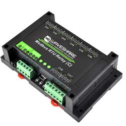
Modbus-RTU-Relay-C User Guide
Overview
Electrical Safety Precautions
- This product should be operated and used by professional electricians or technical personnel. During use, please ensure electrical safety and take protective measures such as anti-leakage and insulation.
- Before installing, maintaining, or replacing relay equipment, make sure to turn off the power and unplug the device.
- Do not attempt to dismantle relay equipment to avoid damaging the device or risking electric shock.
- Please properly install and place the relay equipment. Avoid using it in damp, overly hot, or flammable environments to prevent safety accidents due to improper installation or use.
Specifications
| Power Supply | DC 7~36V |
|---|---|
| Communication Interface | RS485 |
| Communication Baudrate | 4800,9600,19200,38400,57600,115200,128000,256000 |
| Default Communication Format | 9600,N,8,1 |
| Relay Channels | 8 Channels |
| Relay Type | Magnetic latching relay |
| Contact Form | 1NO 1NC |
| Contact Load | ≤10A 250V AC 或 ≤10A 28V DC |
| Modbus Protocol | Standard Modbus RTU protocol |
| RS485 Address Setting | 1~255 |
| Indicator | STA: MCU indicator, keep flashing when MCU normally working TXD: Transmit Data indicator, lights up when sending data RRXD: Receive Data indicator, lights up when receiving data |
Precautions
- The module comes out of the factory in the default state, but due to impacts during transportation or installation, its operational state may change. Therefore, it is necessary to reset the relay state when powering on as needed.
- The magnetic latching relay will only supply power when the state is changed, and the relay is usually in a power-off state and only relies on magnetic attachment, so it should be avoided to vibrate the module strongly, and the relay state may be changed when it is impacted.
- The module status information can be saved when powered off and restored when powered on. However, if the relay is powered off when the state is changed, the state may be uncertain, and the state may change when it is shocked, so it is recommended to reset the relay status as needed after each power-on.
- During use, please keep the product away from strong magnetic fields to avoid changes in the operating voltage and reset voltage.
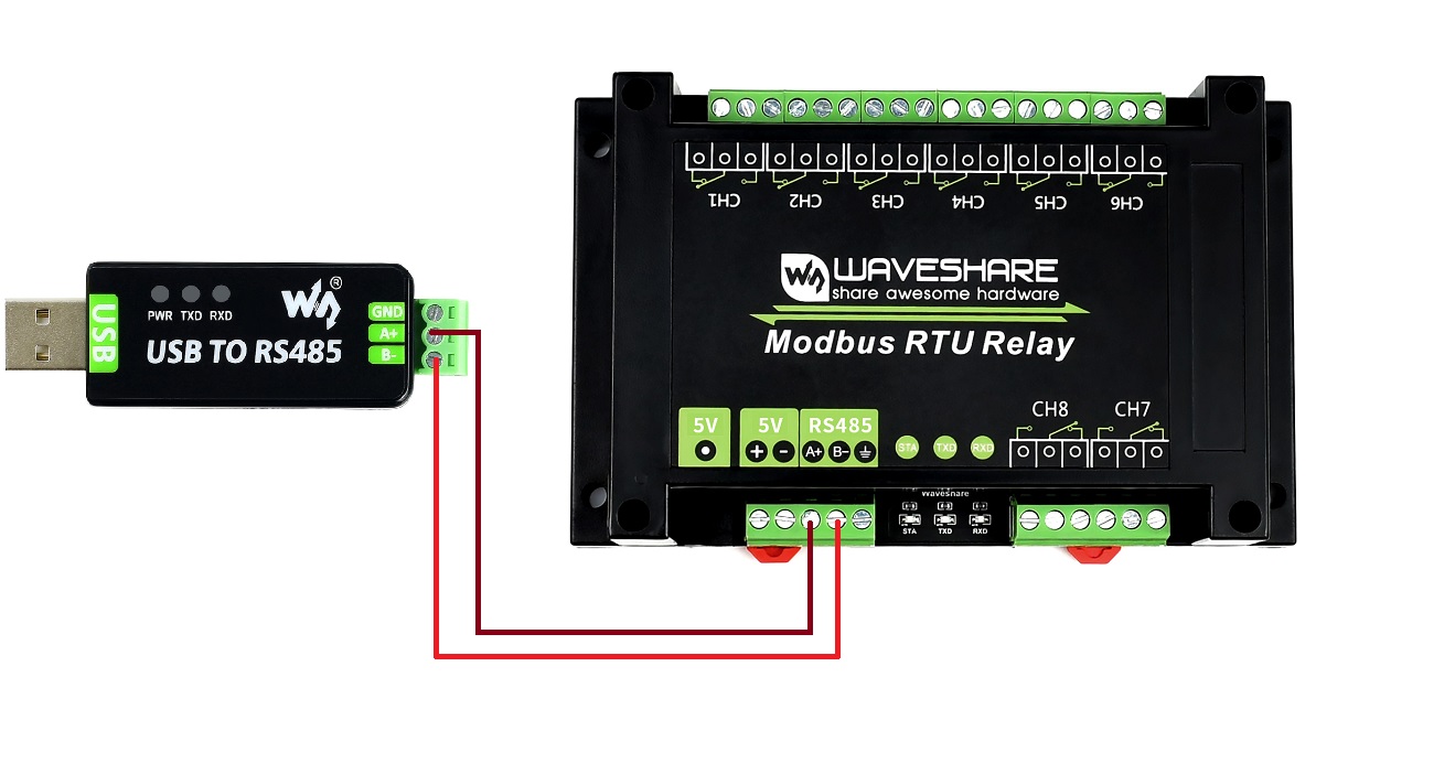
Hardware Connection
- Connect the USB TO 485 to the target boards via cables, A-A and B-B connected as shown below:
Example Demonstration
The demo shows how the following two software operate.
SSCOM serial port debugging assistant is more convenient to operate, free of installation, and more convenient for complete display and analysis of instructions, but the disadvantage is that the data is not intuitive.
Modbus Poll software is directly operated on the register, and the data display is more convenient to observe, but the disadvantage is that the instruction is not displayed completely, so you need to be familiar with the Modbus register operation.
You can test using any method. It is recommended to use the SSCOM serial port debugging assistant software for the first test.
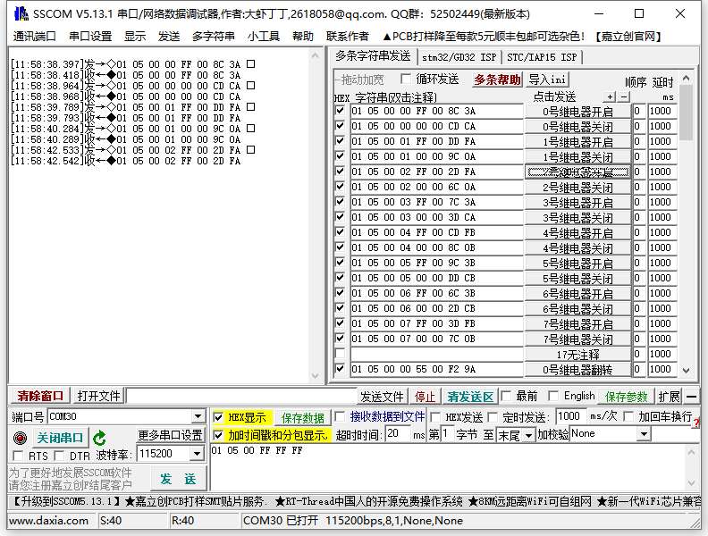
SSCOM Serial Port Debugging Assistant
- Download SSCOM Serial port debugging assistant and open it on the computer, open the corresponding port number, and set the baud rate as 9600. Click Multi-Char to open the Send Multi-Char window, and click the function to send the corresponding command.
- If you need to send other commands, choose SendHEX. For checksum validation, select ModbusCRC16. After entering the first six bytes of the command, clicking SEND will automatically add the CRC check code.
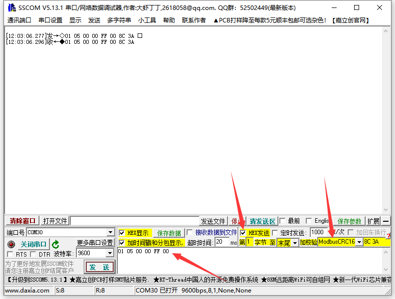
- For detailed control commands, please see the development protocol.
Modbus Poll Software
- The serial port software is not convenient to observe the data, you can choose Modbus Poll software to read the data. Download and install the Modbus Poll software.
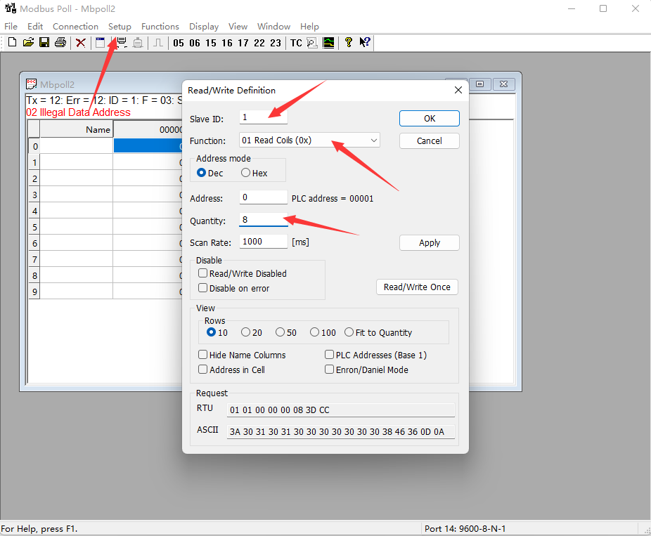
- Open the software, select Setup->Read/Write Definition, select the actual device address for Slave ID, select 01 Read Coils function code for Function, and change Quantity to 8 channels. Click OK to confirm.
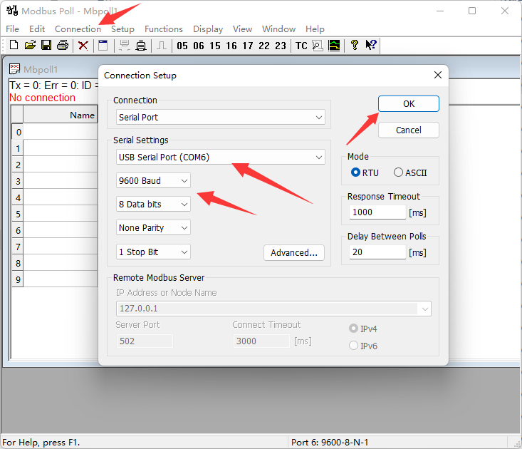
- Select Connection->Connect..., choose the corresponding serial port, set the baud rate to 9600, and select 8 Data bits and None Parity. Click OK to connect.
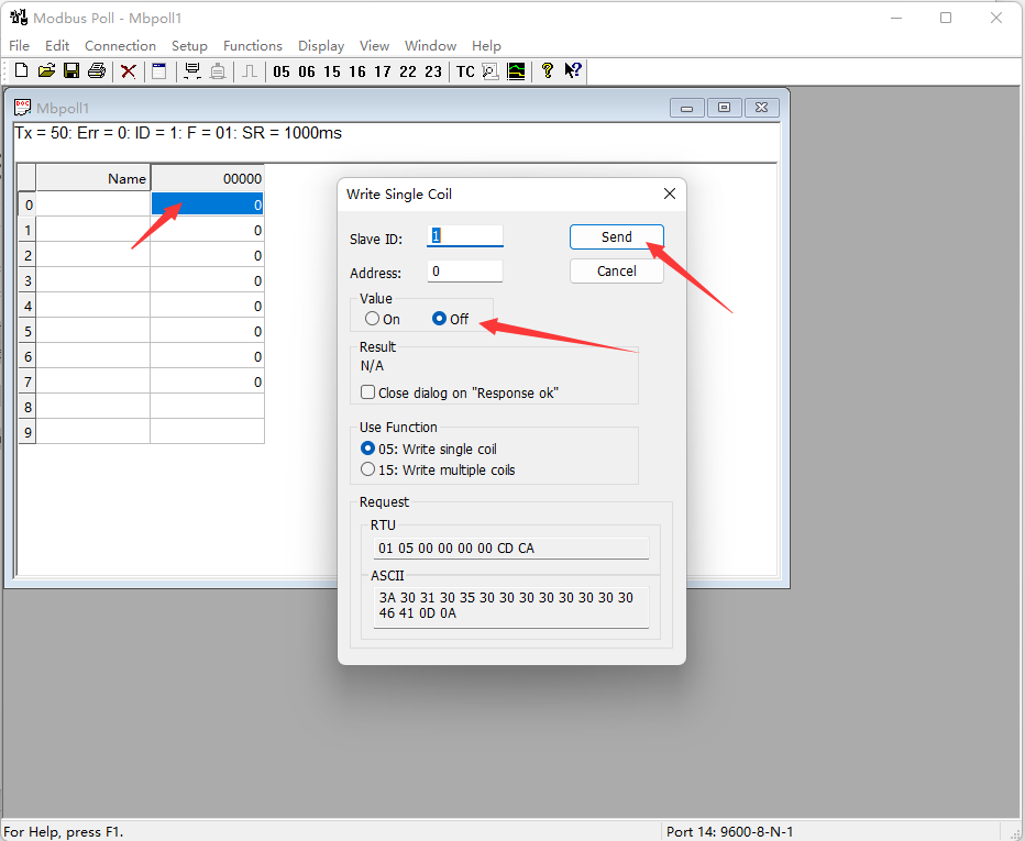
- After the connection is normal, you can check the current relay status. Select the corresponding channel, then double-click the status value to pop up the send page. Choose On or Off, then Click Send to control the relay opening and closing.
Demo Test
Note: RS485 can not be directly connected to the serial port of the Raspberry Pi, otherwise it may burn the device, you need to add 485 level conversion. For Raspberry Pi, it is recommended to work with the RS485 CAN HAT module. For NUCLEO-F103RB and Arduino, it is recommended to work with the RS485 CAN Shield module.
Raspberry Pi
Open the Raspberry Pi terminal and enter the following command to enter the configuration interface
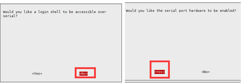
sudo raspi-config
Select Interfacing Options -> Serial, disable shell access, and enable the hardware serial port
Then restart Raspberry Pi:
sudo reboot
Open the /boot/config.txt file, find the following configuration statement to enable the serial port, if not, you can add it to the end of the file.
enable_uart=1
For Raspberry Pi 3B users, the serial port is used for Bluetooth and needs to be commented out:
#dtoverlay=pi3-miniuart-bt
Then restart Raspberry Pi:
sudo reboot
Insert the RS485 CAN HAT into the Raspberry Pi, and connect the Modbus RTU Relay module to RS485 CAN HAT through A and B.
If you are using other 485 devices, make sure to connect A-A, B-B.< br/> Run the following commands to run the demo:
sudo apt-get install unzip
wget https://files.waveshare.com/wiki/Modbus%20RTU%20Relay/Modbus_RTU_Relay_Code.zip
unzip Modbus_RTU_Relay_Code.zip
cd Modbus_RTU_Relay_Code/Python3
sudo python3 main.py
STM32
The STM32 demo is based on the NUCLEO-F103RB and RS485 CAN Shield module.
Find the STM32 demo file directory and open the STM32 project. Please note that the keil5 software is installed before use, and download the demo to the development board.
Normal operation of the relay module will sequentially open and then close the channels. The serial port will output the commands to be sent.
Arduino
The Arduino demo is based on the UNO PLUS and RS485 CAN Shield module.
Use the Arduino IDE to open the demo, select the corresponding development board, and download the demo.
Normal operation of the relay module will sequentially open and then close the channels. The serial port will output the commands to be sent.
Development Protocol
Function Code Introduction
| Function Code | Description | Note |
|---|---|---|
| 01 | Read coil status | Read relay status |
| 03 | Read holding register | Read the address and version |
| 05 | Write single coil | Write single relay |
| 06 | Write single register | Set the baud rate and address |
| 0F | Write multiple coils | Write all relays |
Register Address Introduction
| Address (HEX) | Address storage content | Register value | Permission | Modbus Function Code |
|---|---|---|---|---|
| 0x0000 …… 0x0007 | Channel 1~8 relay address | 0xFF00: relay on 0x0000: relay off 0x5500: relay toggle | Read/Write | 0x01, 0x05, 0x0F |
| 0x00FF | Control all relays | 0xFF00: all relays on 0x0000: all relays off 0x5500: all relays toggle | Write | 0x05 |
| 0x0100 …… 0x0107 | Channel 1~8 relay toggle | 0xFF00: relay toggle 0x0000: relay unchanged | Write | 0x05, 0x0F |
| 0x01FF | All relays toggle | 0xFF00: all relays toggle 0x0000: all relays unchanged | Write | 0x05 |
| 0x0200 …… 0x0207 | Channel 1~8 relay flash on | Interval time: data*100ms Value: 0x0007, Interval time: 7*100MS = 700MS | Write | 0x05 |
| 0x0400 …… 0x0407 | Channel 1~8 relay flash off | Interval time: data*100ms Value: 0x0007, Interval time: 7*100MS = 700MS | Write | 0x05 |
| 4x2000 | UART Parameter | The high eight bits indicate the parity mode: 0x00~0x02 The low eight bits indicate the baud rate mode: 0x00~0x07 | Read/Write | 0x03, 0x06 |
| 4x4000 | Device Address | Directly store Modbus address Device address: 0x0001-0x00FF | Read/Write | 0x03, 0x06 |
| 4x8000 | Software Version | Converting to decimal and then shifting the decimal point two places to the left will represent the software version 0x0064 = 100 = V1.00 | Read | 0x03 |
Modbus RTU Command Introduction
Control Single Relay
Send code: 01 05 00 00 FF 00 8C 3A
| Field | Description | Note |
|---|---|---|
| 01 | Device Address | 0x00 indicates the broadcast address, 0x01-0xFF indicates the device address |
| 05 | 05 Command | Relay control |
| 00 00 | Address | The register address of the relay to be controlled, 0x0000-0x0007 |
| FF 00 | Command | 0xFF00: relay on; 0x0000: relay off; 0x5500: relay toggle |
| 8C 3A | CRC16 | The CRC16 checksum of the first 6 bytes of data |
Return code: 01 05 00 00 FF 00 8C 3A
| Field | Description | Note |
|---|---|---|
| 01 | Device Address | 0x00 indicates the broadcast address, 0x01-0xFF indicates the device address |
| 05 | 05 Command | Relay control |
| 00 00 | Address | The register address of the relay to be controlled, 0x0000-0x0007 |
| FF 00 | Command | 0xFF00: relay on; 0x0000: relay off; 0x5500: relay toggle |
| 8C 3A | CRC16 | The CRC16 checksum of the first 6 bytes of data |
For example: [Address 1 device]:
Relay 0 on: 01 05 00 00 FF 00 8C 3A
Relay 0 off: 01 05 00 00 00 00 CD CA
Relay 1 on: 01 05 00 01 FF 00 DD FA
Relay 1 off: 01 05 00 01 00 00 9C 0A
Relay 2 on: 01 05 00 02 FF 00 2D FA
Relay 2 off: 01 05 00 02 00 00 6C 0A
Relay 3 on: 01 05 00 03 FF 00 7C 3A
Relay 3 off: 01 05 00 03 00 00 3D CA
Relay 0 toggle: 01 05 00 00 55 00 F2 9A
Relay 1 toggle: 01 05 00 01 55 00 A3 5A
Relay 2 toggle: 01 05 00 02 55 00 53 5A
Relay 3 toggle: 01 05 00 03 55 00 02 9A
Control All Relays
Send code: 01 05 00 FF FF 00 BC 0A
| Field | Description | Note |
|---|---|---|
| 01 | Device Address | 0x00 indicates the broadcast address, 0x01-0xFF indicates the device address |
| 05 | 05 Command | Relay control |
| 00 FF | Address | Fixed 0x00FF |
| FF 00 | Command | 0xFF00: relay on; 0x0000: relay off; 0x5500: relay toggle |
| BC 0A | CRC16 | The CRC16 checksum of the first 6 bytes of data |
Return code: 01 05 00 FF FF 00 BC 0A
| Field | Description | Note |
|---|---|---|
| 01 | Device Address | 0x00 indicates the broadcast address, 0x01-0xFF indicates the device address |
| 05 | 05 Command | Relay control |
| 00 FF | Address | Fixed 0x00FF |
| FF 00 | Command | 0xFF00: relay on; 0x0000: relay off; 0x5500: relay toggle |
| BC 0A | CRC16 | The CRC16 checksum of the first 6 bytes of data |
For example: [Address 1 device]:
All relays on: 01 05 00 FF FF 00 BC 0A
All relays off: 01 05 00 FF 00 00 FD FA
All relays toggle: 01 05 00 FF 55 00 C2 AA
Read Relay Status
Send code: 01 01 00 00 00 08 3D CC
| Field | Description | Note |
|---|---|---|
| 01 | Device Address | 0x00 indicates the broadcast address, 0x01-0xFF indicates the device address |
| 01 | 01 Command | Query relay status |
| 00 00 | Relay Start Address | The register address of the relay, 0x0000 - 0x0007 |
| 00 08 | Relay Number | The number of relays to be read, which must not exceed the maximum number of relays |
| 3D CC | CRC16 | The CRC16 checksum of the first 6 bytes of data |
Receive code: 01 01 01 00 51 88
| Field | Description | Note |
|---|---|---|
| 01 | Device Address | 0x00 indicates the broadcast address, 0x01-0xFF indicates the device address |
| 01 | 01 Command | Query relay status |
| 01 | Byte Number | The number of all bytes of the returned status information |
| 00 | Query status | Received relay status Bit0: the first relay status; Bit1: the second relay status; And so on, with the idle high bit being zero |
| 51 88 | CRC16 | The CRC16 checksum of the first 6 bytes of data |
For example: [Address 1 device]
Send: 01 01 00 00 00 08  3D CC
Receive: 01 01 01 00 51 88    //all relays off
Send: 01 01 00 00 00 08  3D CC
Receive: 01 01 01 01 90 48    //Relay 0 is on, others are off
Send: 01 01 00 00 00 08  3D CC
Receive: 01 01 01 41 91 B8 //Relay 0 and 6 are on, others are off
Write Relay Status
Send code: 01 0F 00 00 00 08 01 FF BE D5
| Field | Description | Note |
|---|---|---|
| 01 | Device Address | 0x00 indicates the broadcast address, 0x01-0xFF indicates the device address |
| 0F | 0F Command | Write relay status |
| 00 00 | Relay Start Address | The register address of the relay to be controlled, 0x0000 - 0x0007 |
| 00 08 | Relay Number | The number of relays to be operated, which must not exceed the maximum number of relays |
| 01 | Byte Number | The byte number of the status |
| FF | Relay Status | Bit0: the first relay status; Bit1: the second relay status; And so on, with the idle high bit being zero |
| BE D5 | CRC16 | The CRC16 checksum of the first 6 bytes of data |
Receive code: 01 0F 00 00 00 08 54 0D
| Field | Description | Note |
|---|---|---|
| 01 | Device Address | 0x00 indicates the broadcast address, 0x01-0xFF indicates the device address |
| 0F | 0F Command | Control all registers |
| 00 00 | Relay Start Address | The register address of the relay to be controlled, 0x0000 - 0x0007 |
| 00 08 | Relay Number | The number of relays to be operated |
| 54 0D | CRC16 | The CRC16 checksum of the first 6 bytes of data |
For example: [Address 1 device]
All relays on: 01 0F 00 00 00 08 01 FF BE D5
All relays off: 01 0F 00 00 00 08 01 00 FE 95
0-1 on; 2-7 off: 01 0F 00 00 00 08 01 03 BE 94
Relay Flash ON/OFF Command
Send code: 01 05 02 00 00 07 8D B0
| Field | Description | Note |
|---|---|---|
| 01 | Device Address | 0x00 indicates the broadcast address, 0x01-0xFF indicates the device address |
| 05 | 05 Command | Single control command |
| 02 | Flash on flash off | 02: flash on, 04: flash off |
| 00 | Relay Address | The address of the relay to be controlled, 0x00~0x07 |
| 00 07 | Interval Time | The interval time: data*100ms Value: 0x0007, Interval time: 7*100MS = 700MS The maximum setting for the flash-on flash-off time is 0x7FFF |
| 8D B0 | CRC16 | The CRC16 checksum of the first 6 bytes of data |
Receive code: 01 05 02 00 00 07 8D B0
| Field | Description | Note |
|---|---|---|
| 01 | Device Address | 0x00 indicates the broadcast address, 0x01-0xFF indicates the device address |
| 05 | 05 Command | Single control command |
| 02 | Flash on flash off | 02: flash on, 04: flash off |
| 00 | Relay Address | The address of the relay to be controlled, 0x00~0x07 |
| 00 07 | Interval Time | The interval time: data*100ms Value: 0x0007, Interval time: 7*100MS = 700MS The maximum setting for the flash-on flash-off time is 0x7FFF |
| 8D B0 | CRC16 | The CRC16 checksum of the first 6 bytes of data |
For example: [Address 1 device]
Relay 0 flash on: 01 05 02 00 00 07 8D B0  //700MS = 7*100MS = 700MS
Relay 1 flash on: 01 05 02 01 00 08 9C 74  //800MS
Relay 0 flash off: 01 05 04 00 00 05 0C F9  //500MS
Relay 1 flash off: 01 05 04 01 00 06 1D 38  //600MS
Set Baudrate Command
Send code: 01 06 20 00 00 05 42 09
| Field | Description | Note |
|---|---|---|
| 01 | Device Address | 0x00 indicates the broadcast address, 0x01-0xFF indicates the device address |
| 06 | 06 command | Set the baud rate and device address |
| 20 00 | Baud rate register | 0x2000: set the baud rate |
| 00 | Parity Method | x00: no parity, 0x01: even parity; 0x02: odd parity |
| 05 | Baud Rate Value | Corresponding baud rate 0x00: 4800 0x01: 9600 0x02: 19200 0x03: 38400 0x04: 57600 0x05: 115200 0x06: 128000 0x07: 256000 |
| 42 09 | CRC16 | The CRC16 checksum of the first 6 bytes of data |
Receive code: 01 06 20 00 00 05 42 09
| Field | Description | Note |
|---|---|---|
| 01 | Device Address | 0x00 indicates the broadcast address, 0x01-0xFF indicates the device address |
| 06 | 06 command | Set the baud rate and device address |
| 20 00 | Baud rate register | 0x2000: set the baud rate |
| 00 | Parity Method | x00: no parity, 0x01: odd parity; 0x02: even parity |
| 05 | Baud Rate | Corresponding baud rate 0x00: 4800 0x01: 9600 0x02: 19200 0x03: 38400 0x04: 57600 0x05: 115200 0x06: 128000 0x07: 256000 |
| 42 09 | CRC16 | The CRC16 checksum of the first 6 bytes of data |
For example: [Address 1 device]
Set the baud rate as 4800: 01 06 20 00 00 00 82 0A
Set the baud rate as 9600: 01 06 20 00 00 01 43 CA
Set the baud rate as 115200: 01 06 20 00 00 05 42 09
Set Device Address Command
Send code: 01 06 40 00 00 01 5D CA
| Field | Description | Note |
|---|---|---|
| 01 | Device Address | 0x00 indicates the broadcast address, 0x01-0xFF indicates the device address |
| 06 | 06 command | Set the baud rate and device address |
| 40 00 | Device address register | 0x4000: set the device address |
| 00 01 | Device Address | Set the device address, 0x0001-0x00FF |
| 5D CA | CRC16 | The CRC16 checksum of the first 6 bytes of data |
Receive code: 01 06 40 00 00 01 5D CA
| Field | Description | Note |
|---|---|---|
| 01 | Device Address | 0x00 indicates the broadcast address, 0x01-0xFF indicates the device address |
| 06 | 06 command | Set the baud rate and device address |
| 40 00 | Device address register | 0x4000: set the device address |
| 00 01 | Device Address | Set the device address, 0x0001-0x00FF |
| 5D CA | CRC16 | The CRC16 checksum of the first 6 bytes of data |
For example: [Address 1 device]
Set the device address as 0x01: 00 06 40 00 00 01 5C 1B
Set the device address as 0x02: 00 06 40 00 00 02 1C 1A
Set the device address as 0x03: 00 06 40 00 00 03 DD DA
Read Device Address Command
Send code: 00 03 40 00 00 01 90 1B
| Field | Description | Note |
|---|---|---|
| 00 | Device Address | 0x00 indicates the broadcast address, 0x01-0xFF indicates the device address |
| 03 | 03 Command | Read the device address |
| 40 00 | Device address register | 0x4000: read the device address |
| 00 01 | Byte Number | Fixed 0x0001 |
| 90 1B | CRC16 | The CRC16 checksum of the first 6 bytes of data |
Receive code: 00 03 02 00 01 44 44
| Field | Description | Note |
|---|---|---|
| 00 | Device Address | 0x00 indicates the broadcast address, 0x01-0xFF indicates the device address |
| 03 | 03 Command | Read the software version and device address |
| 02 | Byte Number | The number of bytes returned |
| 00 01 | Device Address | Set the device address, 0x0001-0x00FF |
| 44 44 | CRC16 | The CRC16 checksum of the first 6 bytes of data |
For example: [Address 2 device]
Send: 00 03 40 00 00 01 90 1B
Receive: 00 03 02 00 02 04 45     //Address: 0x02
Read Software Version Command
Send code: 01 03 80 00 00 01 AD CA
| Field | Description | Note |
|---|---|---|
| 01 | Device Address | 0x00 indicates the broadcast address, 0x01-0xFF indicates the device address |
| 03 | 03 Command | Read the software version and device address |
| 80 00 | Software version register | 0x4000: read the device address, 0x8000: read software version |
| 00 01 | Byte Number | Fixed 0x0001 |
| AD CA | CRC16 | The CRC16 checksum of the first 6 bytes of data |
Receive code: 01 03 02 01 2C B8 09
| Field | Description | Note |
|---|---|---|
| 01 | Device Address | 0x00 indicates the broadcast address, 0x01-0xFF indicates the device address |
| 03 | 03 Command | Read the software version and device address |
| 02 | Byte Number | The number of bytes returned |
| 01 2C | Software Version | Converting to decimal and then shifting the decimal point two places to the left will represent the software version 0x012C = 300 = V3.00 |
| B8 09 | CRC16 | The CRC16 checksum of the first 6 bytes of data |
For example:
Send: 01 03 80 00 00 01 AD CA
Receive: 01 03 02 01 2C B8 09       //0x012C = 300 =V3.00
Exception Function Code
When the received command is incorrect or the device is abnormal, an exception response will be returned in the following format:
Receive: 01 85 03 02 91
| Field | Description | Note |
|---|---|---|
| 01 | Device Address | 0x00 indicates the broadcast address, 0x01-0xFF indicates the device address |
| 85 | Exception Function Code | Exception function code = Request function code + 0x80 |
| 03 | Byte Number | Exception Code |
| 02 91 | CRC16 | The CRC16 checksum of the first 6 bytes of data |
An exception code is a single-byte value that indicates the type of error. Several commonly used exception codes defined by the Modbus protocol:
| Exception Code | Name | Description |
|---|---|---|
| 0x01 | Illegal Function | The requested function code is not supported |
| 0x02 | Illegal Data Address | The requested data address is incorrect |
| 0x03 | Illegal Data Value | The requested data value or operation cannot be executed |
| 0x04 | Server Failure | Server equipment failure |
| 0x05 | Response | The request has been received and is being processed |
| 0x06 | Device Busy | The device is currently busy and cannot perform the requested operation |
Related Resources
FAQ
Support
Monday-Friday (9:30-6:30) Saturday (9:30-5:30)
Email: services01@spotpear.com