


- sales/support
Google Chat:---
- sales
+86-0755-88291180
- sales01
sales@spotpear.com
- sales02
dragon_manager@163.com
- support
tech-support@spotpear.com
- CEO-Complaints
zhoujie@spotpear.com
- Only Tech-Support
WhatsApp:13246739196
- Purchase/Shipping/Refund
WhatsApp:13424403025
CM4 OpenWrt Tutorial
Compile Environment Building
To compile OpenWrt, you need to compile it in the Linux environment. You can use the VM virtual machine to realize the compilation. At the same time, you need to be able to access the Internet, otherwise, the basic compilation will fail. Here I use the 20.04.1-Ubuntu (Ubuntu self-installation) environment to operate.
1. To update the software list, run the command line in the terminal:
sudo apt-get -y update
2. Update software to run:
sudo apt-get -y upgrade
3. Install compiling environment dependencies:
sudo apt-get -y install build-essential asciidoc binutils bzip2 gawk gettext git libncurses5-dev libz-dev patch python3.5 python2.7 unzip zlib1g-dev lib32gcc1 libc6-dev-i386 subversion flex uglifyjs git-core gcc-multilib p7zip p7zip-full msmtp libssl-dev texinfo libglib2.0-dev xmlto qemu-utils upx libelf-dev autoconf automake libtool autopoint device-tree-compiler g++-multilib antlr3 gperf wget swig rsync
Download the source code to install the configuration components
#create folder
  mkdir openwrt
#Give folder permissions, if you don't add permissions, you will get an error: how to enter the directory
sudo chmod 777 openwrt
cd openwrt
#download source code
git clone https://git.openwrt.org/openwrt/openwrt.git
#Enter the corresponding directory again cd openwrt
cd openwrt
#update source
  ./scripts/feeds update -a
#Install
  ./scripts/feeds install -a
#Function configuration editing
make menuconfig
Normally, the following configuration interface will be entered (the operation is relatively simple, you can use the direction key and Enter to control):
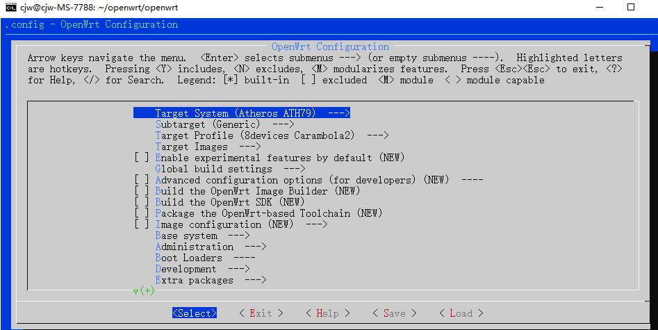
- According to the CM4-DUAL-ETH-BASE hardware selection is as follows:
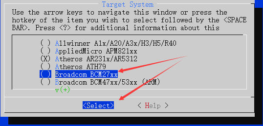
- Select the corresponding firmware according to the hardware, move the cursor up and down to the position as shown in the figure (Target System (Atheros ATH79)), then, according to the left and right arrow keys, select and press Enter to enter, and then select Broadcom BCM27XX:
- After pressing Enter, it will return to the home page, and the relevant information will be changed to Raspberry Pi:
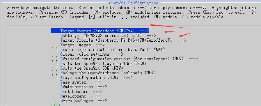
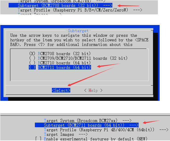
- Change the model of the corresponding target board. We use CM4 here, so here we choose BCM2711 64bit (pi3 zero does not need to be changed)
Enter the LUCI configuration interface and enable the web management function.
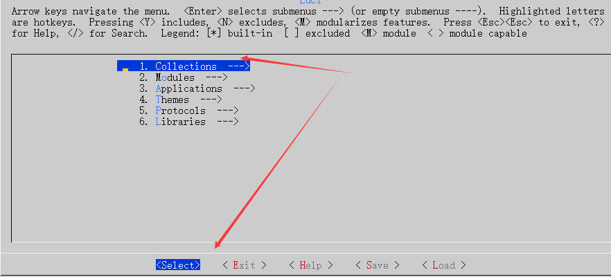
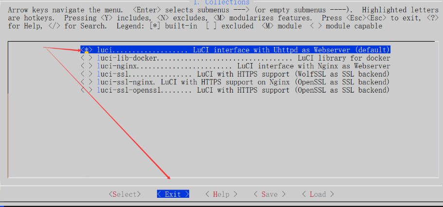
LuCI--->1.Collections--->luci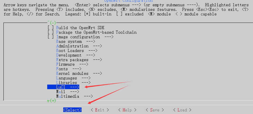
- Enter 1. Collections to open the Web management interface, and then you can manage your smart router through the Web.
- Use space to select the address in front of Luci with *, then exit and return to the previous layer.
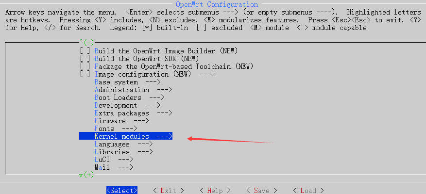
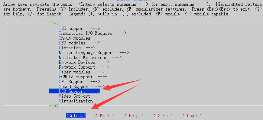
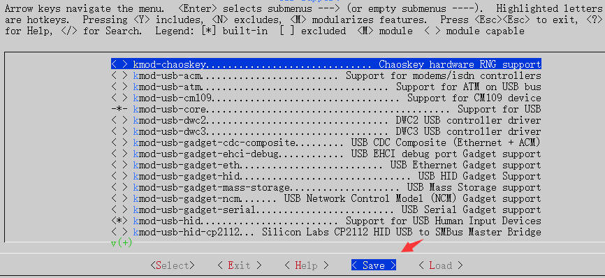
- Enter to edit Kernel modules kernel module, find and enter Kernel modules--->USB Support--->
-*- kmod-usb-core

<*> kmod-usb-hid
-*- kmod-usb-net
<*> kmod-usb-net-rtl8152

-*- kmod-usb2

<*> kmod-usb2-pci

<*> kmod-usb3
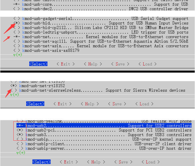
- Save:
Then select exit, return to the previous layer, and then click Exit.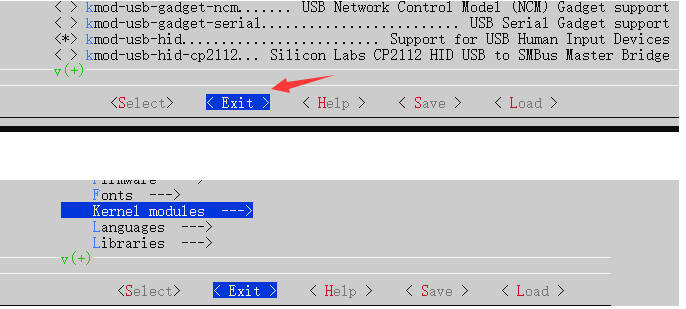
System Compilation
- Execute "make -j8 download V=s && make -j1 V=s" to download the "dl" library and enable threaded compilation:
make -j8 download V=s && make -j1 V=s
It is recommended to execute it before going to bed at night as the waiting time will be very long.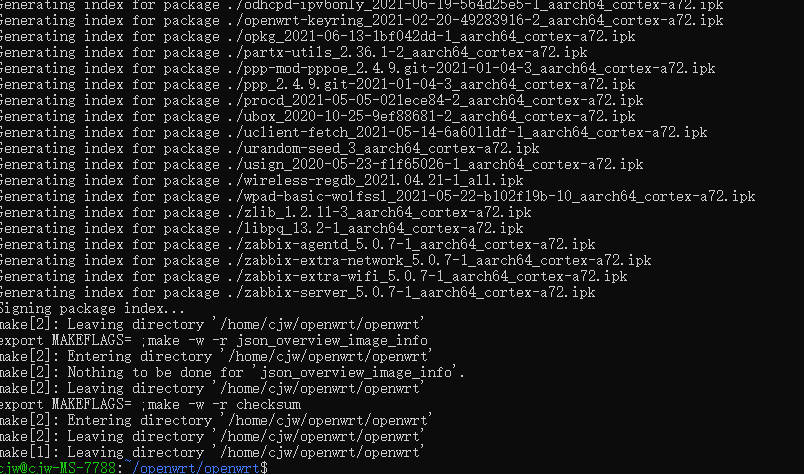
Find the successfully compiled system in the directory "~/openwrt/openwrt/bin/targets/bcm27xx/bcm2711". You can copy the system to Windows to program (or directly on your ubuntu) to CM4 or program to SD card.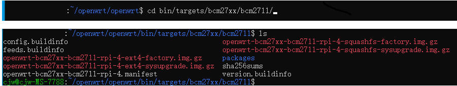
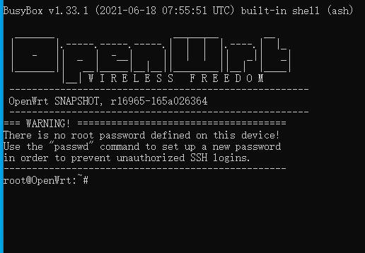
System Login
- The default compiled IP address is 192.168.1.1, please directly set the IP address of your computer to 192.168.1.0/24 segment, and open the 192.168.1.1 web management router through the web page, or remotely log in to control it through SSH.
- We connect to the ETH0 interface through the computer and then log in directly to 192.168.1.1 via ssh.
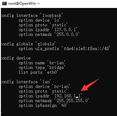
- The default management IP address can be modified via SSH. You can edit the "vi /etc/config/network" file to change.
vi /etc/config/network
- Move the cursor to 192.168.1.1, and modify the IP address according to your situation (ensuring it doesn't conflict with the management IP of your ONT).
After modification, please restart it.
After restarting, you can see that the IP of our computer jumps to the same segment as the IP set.
The browser can log in through the management address. The management IP has just been changed here. If it has not been changed, it is still 192.168.1.1 (how many IPs have been modified before, and how many IPs are entered in the browser), and directly choose to log in (password: root).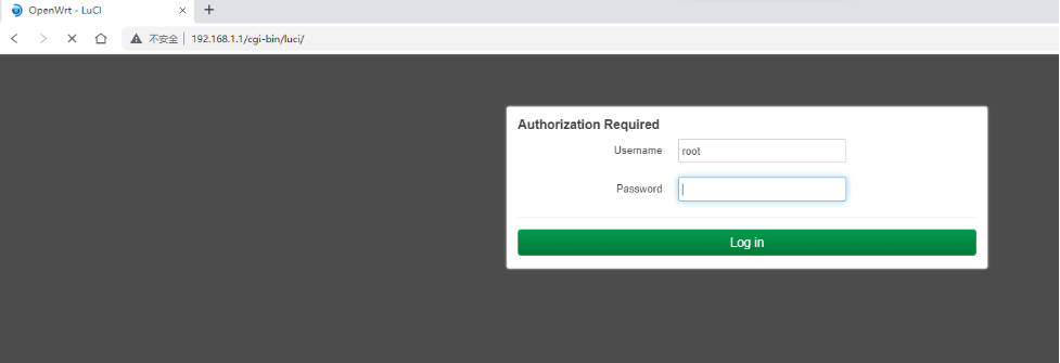
The login interface is as follows: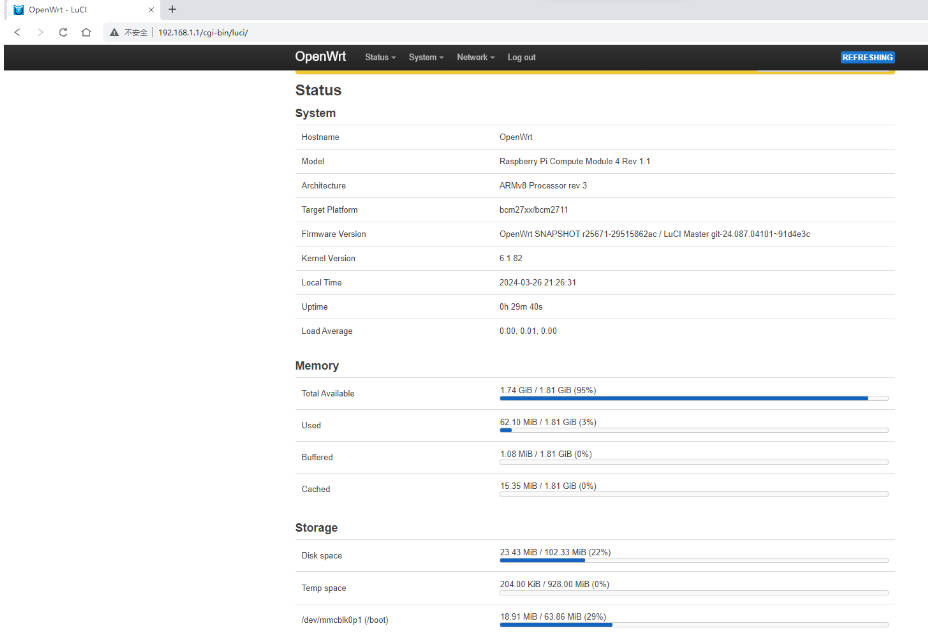
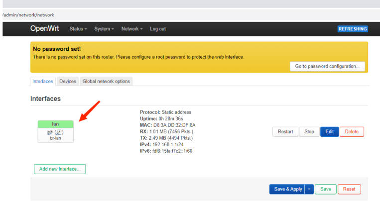
Set up the router according to the topology
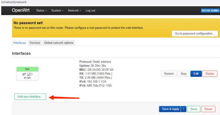
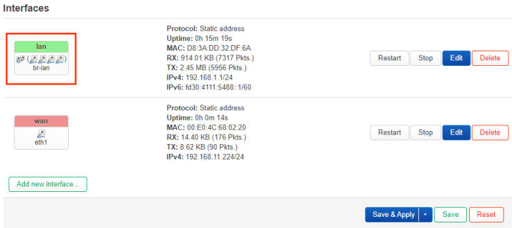
- Click on LAN --> Interface to configure:
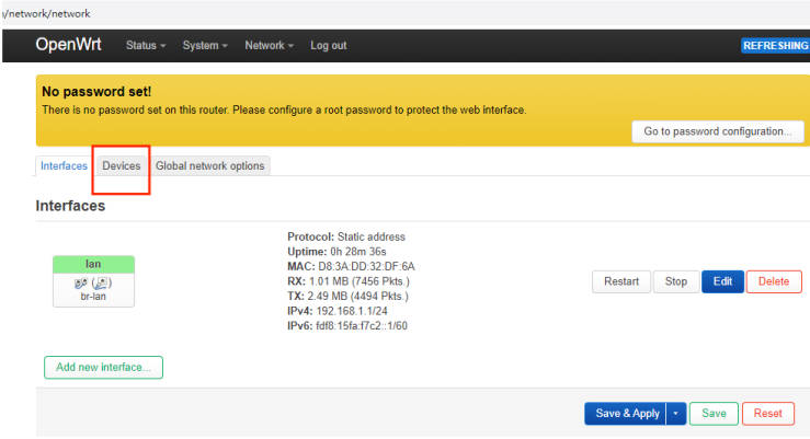
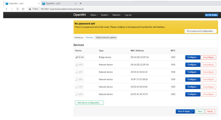
- Click the device to see the identified network port information. There are two network ports on the board, and two network ports are identified. ETH0 is used as the bridge subnet device by default.
- The board comes with two USB ports, which can expand multiple USB network ports. Here I have connected three more USB network ports. A total of 5 eth network ports can be identified as shown in the figure below.
- According to the topology diagram, we set ETH1 as the WAN port, click Network--->Interface--->Add New Interface:
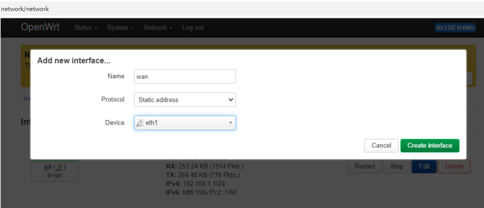
- Enter the "Add New Interface" pop-up window.
- Name: The default firewall is that the LAN port forwards the WAN port, so the name here corresponds to wan. If you change it, you need to change the firewall policy yourself;
- Protocol: Generally, there are two working modes of optical modem: one is PPOE playback mode, and the other is optical modem automatic dialing. Just fill in the optical modem subnet IP (usually DHCP can automatically obtain IP), you can fill in according to your actual situation, we use a static address here. And we select the corresponding ETH1.
- Then create an interface, and then enter the wan port editing page.
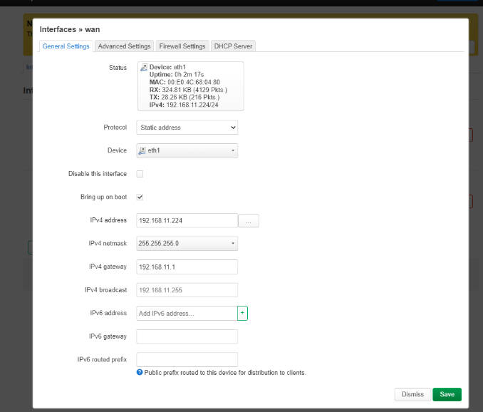
According to the displayed situation, we fill in the local IP of the wan port, the gateway points to the next IP address, which is the IP address given by your optical modem, then enter the advanced settings to set DNS, and then select Save.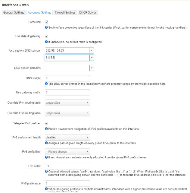
After returning, you need to click Save and Apply to take effect.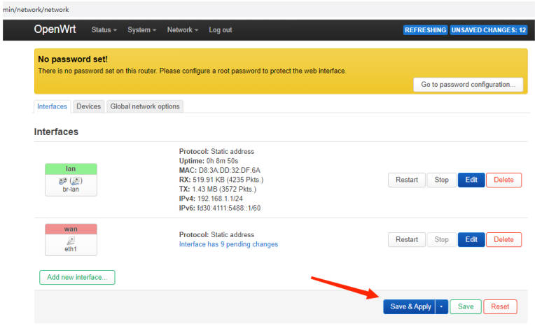
Test Network - Diagnose Network - Use network tools to see if you can access the Internet normally. Then we test the PC terminal networking situation.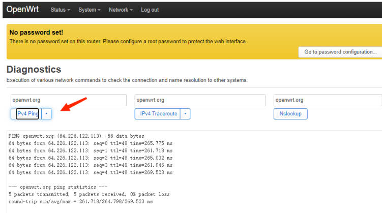
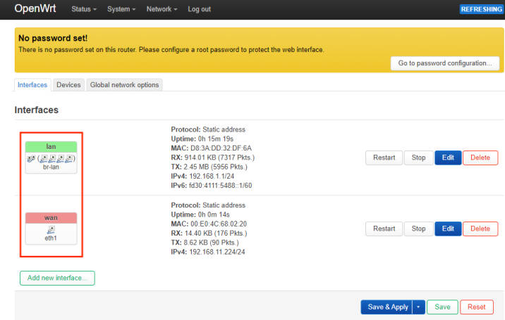
If the test results are as above, it means that your network setup is complete.
Set to add multiple USB network ports as LAN ports
Click Network-->Interface-->Device Configure br-lan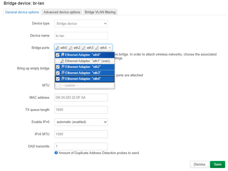
Select ETH2 ETH3 ETH4 in the bridge port as shown in the figure below, then click save, return to the previous layer, click save and apply, and finally click the interface column to see that the br-lan device has 4 ports.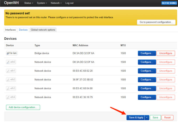
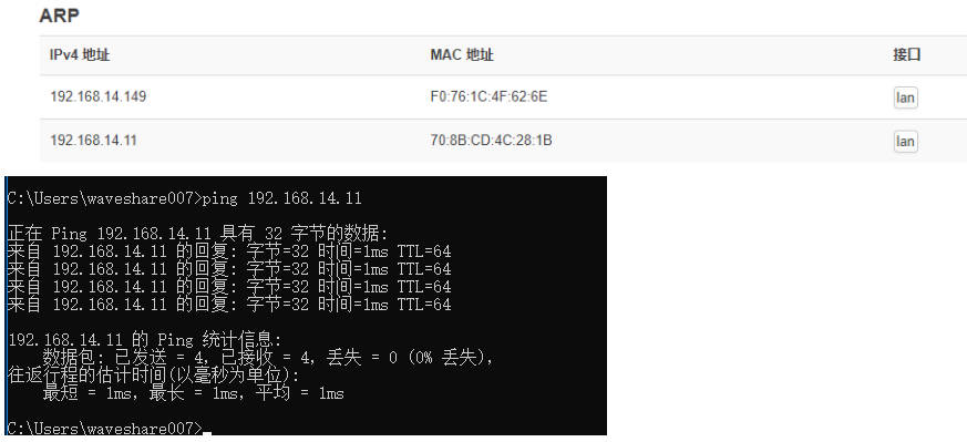
After we connect a device to the ETH4 port, we can check that there are two devices in the arp table to test whether ETH4 can communicate with the ETH0 device normally.
Wireless Seting
- If the version you used in the core is with WIFI, as the wireless model of CM4 is the same as that of PI4, you can manually activate the wireless function.
- Use the command "cd /lib/firmware/brcm/" to enter the brcm directory, and enter the command ls to view the default files in this directory.
cd /lib/firmware/brcm/
ls
cp brcmfmac43455-sdio.raspberrypi,4-model-b.txt brcmfmac43455-sdio.raspberrypi,4-compute-module.txt
# restart after execution
reboot
After restarting, please log in to the web management interface, you can see more wireless options in the network drop-down menu. Please click to enter the wireless settings.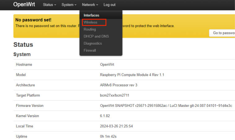
After entering we enable the wireless function.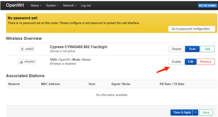
After startup, you can see that the default channel of the radio is 36 channels of the 5G frequency band. It is possible that our wireless terminal equipment may not be able to search for the changed SSID. Select the following to edit the SSID to enter the device configuration.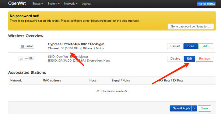
Modify the working frequency as follows. You can also modify the SSID name and working mode in the interface configuration.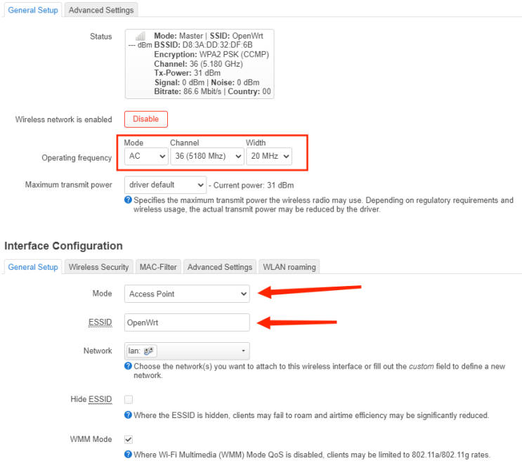
By default, the SSID is open and no password is set. You can enter the wireless security to set the password.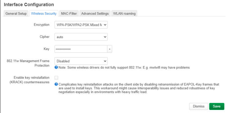
Finally, don't forget to click Save in the lower right corner. Remember to save and apply after returning. If there is no problem with the settings, you can search for the corresponding SSID signal on your wireless device.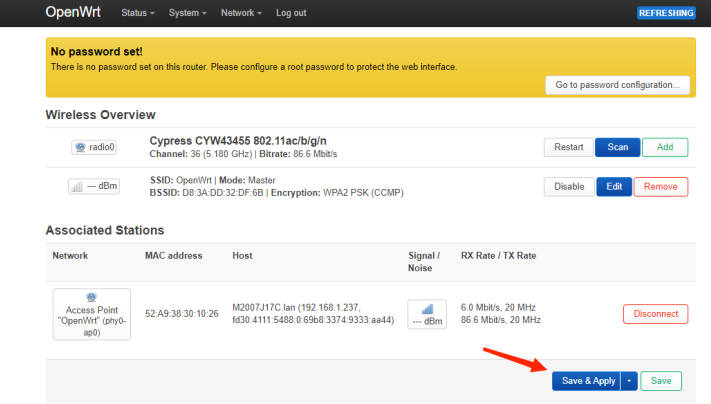
After the mobile phone can search for the corresponding signal connection, you can see the connected device in the wireless.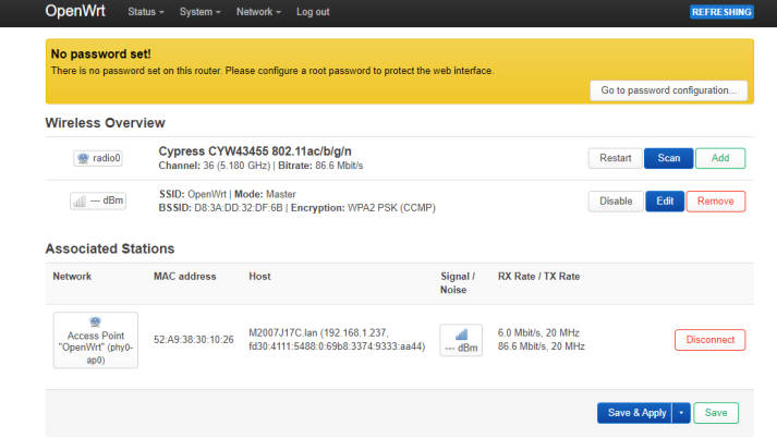