- sales/support
Google Chat:---
- sales
+86-0755-88291180
- sales01
sales@spotpear.com
- sales02
dragon_manager@163.com
- support
tech-support@spotpear.com
- CEO-Complaints
zhoujie@spotpear.com
- Only Tech-Support
WhatsApp:13246739196
- Purchase/Shipping/Refund
WhatsApp:13424403025
CM5-IO-BASE-B User Guide
Overview
Introduction
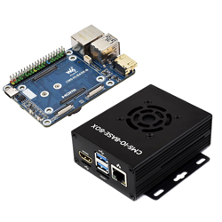
As the IO board of the Raspberry Pi Compute Module 5, CM5-IO-BASE-B is a baseboard that can be used with the Raspberry Pi Compute Module 5. With powerful features are integrated into a compact design, it is only the size of a bank card. It comes with two USB3.2 Gen1 ports and two USB2.0 ports onboard, making it convenient for users.
Features and Precautions
1. Do not plug or unplug any device other than USB and HDMI when the device is powered on
2. Type C can be used as a USB SLAVE interface to flash images.
3. Onboard default 2 USB 3.2 Gen1 ports
4. Supports 4 screens to display different contents, adds MIPI DSI driver, regardless of whether a screen is connected, the system will default to connect, the screen will display in split-screen mode (related to the system version)
5. The onboard BOOT button, you can press the BOOT button before powering on, and connect to the computer through Type C to let the device enter the flashing mode
6. Do not connect other devices when using Type C to flash. Insufficient power supply for burning will cause the device to be unrecognized
7. The USB ports have a total maximum power output of 2A
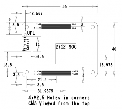
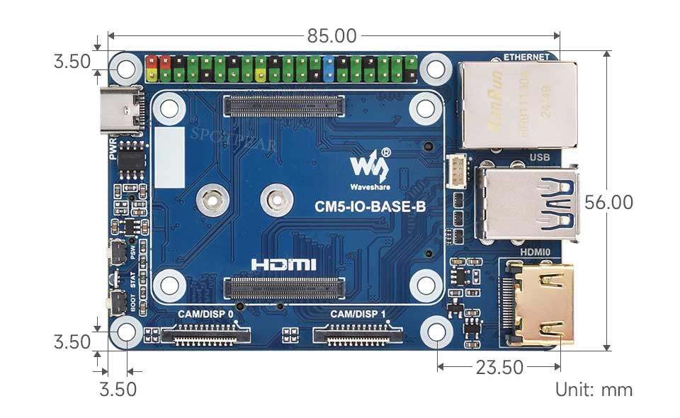
Dimensions
Core Board Size
Baseboard Size
Case Size
Stay tuned...
Image Flashing
How to Flash
Enter burning mode
1. The onboard BOOT button, you can press the BOOT button before powering on, and connect to the computer through Type C to let the device enter the flashing mode
Click here for EMMC version
Click here for LITE version
M.2
1. Enable PCIE interface
PI5B defaults to not having the PCIE interface enabled. Add to /boot/firmware/config.txt:
dtparam=pciex1
2. PCIE is gen2 by default, if you need to enable PCIE gen3, then add following to /boot/firmware/config.txt:
dtparam=pciex1_gen=3
3. After the modification, reboot the PI5, and the device can be recognized.
As shown in the figure below, SM2263 is identified as my SSD solid state drives, and the other PI5 is the RPI chip
4. Partition, skip this step if you have partitioned and formatted on other platforms (Note: partitioning will delete all data on the SSD, proceed with caution)
Lsblk This command is executed to view the disk (if you want to see the details, run the sudo fdisk -l command)Partition: sudo fdisk /dev/nvme0n1 The device number is the total device number, do not add p1, that is just a partition How to use the partitioning tool fdisk: n New partition q Quit without saving p Print the partition table m Print the selection menu D Delete the partition w Save and exit t Modify the ID number Add the partition and execute n, then save and exit with w
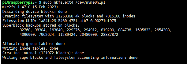
5. Format
sudo mkfs. Execute the command and press Tab key, you will see a lot of different suffixes, and the different suffixes are the formats you need to formatIf I want to format it in ext4 file format, then execute the command: sudo mkfs.ext4 /dev/nvme0n1p1 Wait a moment, once all "done" appear as below, it indicates that the formatting is completed
6. Mount
Create a mount directory
sudo mkdir toshiba
Mount the device
sudo mount /dev/nvme0n1p1 ./toshiba
Check the disk status
df -h
Read/Write Test
Enter the directory where the disk is mounted
cd toshiba
- Free up the memory
sudo sh -c "sync && echo 3 > /proc/sys/vm/drop_caches"
- Copy Raspberry Pi memory content to the hard disk (write)
sudo dd if=/dev/zero of=./test_write count=2000 bs=1024k

- Copy the hard drive content to the Raspberry Pi memory (/etc/fstab read )
sudo dd if=./test_write of=/dev/null count=2000 bs=1024k

- Note: The test results vary for different cards and environments. The Raspberry Pi is significantly affected. If you want to test accurate performance, use a PC for the test
Auto Mount
Test shows there's no issue. If it's not required to be used as a system disk, but only for expanding the disk, set it to auto-mount
sudo nano /etc/fstab

#Add at the end
/dev/nvme0n1p1  /home/pi/toshiba  ext4  defaults  0  0
#/dev/nvme0n1p1 is the device name, /home/pi/toshiba refers to mounting to a directory, ext4 is the file system type, defaults uses the default mount option
#Make the changes take effect (reboot only after testing, otherwise it will fail to mount and boot)
sudo mount -a

#Then reboot
Check the device with lsblk
NVMe SSD Boot
Boot the Raspberry Pi with a TF card first, mount and test it, and make sure the hardware can work properly
Choose one of the following methods
Method 1
1. Run the following command:
sudo raspi-config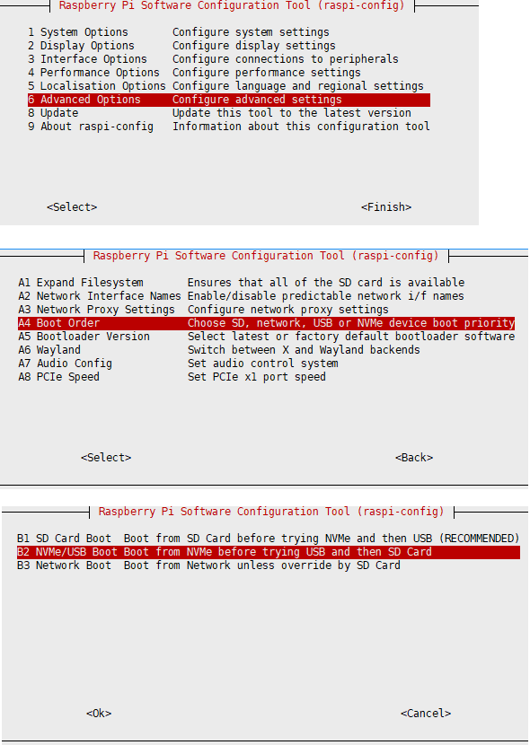
2. Reboot Raspberry Pi
If you find you can't modify it multiple times, please reconnect to the network and then try to modify it (wait for the network to self-calibrate), or modify the file after setting the correct time
3. Burn the system to NVME, then connect the NVME to the expansion board, remove the TF card and power it on again
Method 2
1. Modify the BOOT_ORDER in the Raspberry Pi boot loader configuration:
sudo rpi-eeprom-config --edit Modify BOOT_ORDER=0xf41 to BOOT_ORDER=0xf416For more information, please refer to BOOT_ORDER
2. Reboot Raspberry Pi
If you find you can't modify it multiple times, please reconnect to the network and then try to modify it (wait for the network to self-calibrate), or modify the file after setting the correct time
3. Burn the system to NVME, then connect the NVME to the expansion board, remove the TF card and power it on again
Fan Control
The PI5 fan defaults to starting when the temperature reaches 50 degrees. If you want to control it at other temperatures, you can do so by adding specific content to /boot/firmware/config.txt, for example:
dtparam=fan_temp0=36000,fan_temp0_hyst=2000,fan_temp0_speed=90
dtparam=fan_temp1=40000,fan_temp1_hyst=3000,fan_temp1_speed=150
dtparam=fan_temp2=52000,fan_temp2_hyst=4000,fan_temp2_speed=200
dtparam=fan_temp3=58000,fan_temp3_hyst=5000,fan_temp3_speed=255
Among which:
fan_temp0/1/2/3               Indicates the temperature (36000 means 36℃)

fan_temp0/1/2/3_speed  Indicates the corresponding rotational speed (value up to 255)

fan_temp0/1/2/3_hyst      Indicates the hysteresis temperature
For more details, refer to here
Notice: There are only 4 temperatures, 0, 1, 2 and 3, and it's not possible to set other temperatures. The hysteresis temperature must not exceed the step range between two temperatures
MIPI
Support dual MIPI, customers can freely choose CSI or DSI connections
The DSI screen is 800x480 resolution screen by default, please refer to the corresponding WIKI for other resolution screens
DSI
#Add the following to the config.txt file:
sudo nano /boot/firmware/config.txt
#DSI0
dtoverlay=vc4-kms-dsi-7inch,dsi0
#DSI1
dtoverlay=vc4-kms-dsi-7inch,dsi1
CSI
sudo nano /boot/firmware/config.txt
| Mode | CAM0 setup statement | CAM1 setup statement |
|---|---|---|
| OV9281 | dtoverlay=ov9281,cam0 | dtoverlay=ov9281,cam1 |
| IMX290/IMX327 | dtoverlay=imx290,clock-frequency=37125000,cam0 | dtoverlay=imx290,clock-frequency=37125000,cam1 |
| IMX378 | dtoverlay=imx378,cam0 | dtoverlay=imx378,cam1 |
| IMX219 | dtoverlay=imx219,cam0 | dtoverlay=imx219,cam1 |
| IMX477 | dtoverlay=imx477,cam0 | dtoverlay=imx477,cam1 |
| IMX296 | dtoverlay=imx296,cam0 | dtoverlay=imx296,cam1 |
| IMX708 | dtoverlay=imx708,cam0 | dtoverlay=imx708,cam1 |
Allow one connection to DSI and one connection to CSI, for example, use IMX219 to connect to MIPI1
For example, if you want to connect a DSI display to MIPI0, add the following to the config.txt file
dtoverlay=imx219,cam1
dtoverlay=vc4-kms-dsi-7inch,dsi0

sudo reboot
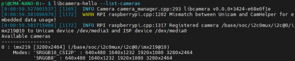
Test Camera
- Enter the camera detection command, and you can see that the camera has been detected
libcamera-hello --list-cameras
- Display the camera screen to the desktop
libcamera-hello -t 0
- Take a photo
libcamera-jpeg -o test.jpg
- Record a 10s video
libcamera-vid -t 10000 -o test.h264
Other commands
Check if the camera is detected
libcamera-hello --list-cameras
Open the corresponding camera
libcamera-hello  --camera 1
libcamera-hello  --camera 0
Take a photo
libcamera-jpeg -o test.jpg
#You can add --camera to specify the camera
Real-Time Clock (RTC)
There is no battery by default, and an additional RTC battery is required
Software Debugging
The default device is /dev/rtc0
Regarding time, by inputting "date" in the command line, you can see the current time. Connecting the Raspberry Pi system to the network will automatically synchronize the time. If the default RTC device is connected and functioning properly, the RTC time will be updated after the automatic network synchronization
sudo hwclock -r Read the RTC time, if there are multiple RTC devices, you can use -f to select the corresponding devices (for example: sudo hwclock -f /dev/rtc1 -r)
Hwclock
System clock -> Hardware clock (RTC)
sudo hwclock -w
Synchronize hardware clock (RTC) -> System clock
sudo hwclock  -s
 #Need to turn off the network, or disable network time synchronization, otherwise it will be changed back
Set the hardware clock time (RTC):
sudo hwclock --set --date="9/8/2023 16:45:05"View the hardware clock (RTC)
sudo hwclock -r
Show version information.
sudo hwclock --verbose
Automated Wakeup
To support a low-power mode for wake-up alarms, add the configuration:
sudo -E rpi-eeprom-config --edit
#Add the following 2 lines
POWER_OFF_ON_HALT=1
WAKE_ON_GPIO=0
#Restart the device after adding (if you connect to the serial port log, you can see that there are update related logs)
sudo reboot
#You can use the following methods to test the function:
echo +600 | sudo tee /sys/class/rtc/rtc0/wakealarm
sudo halt  or  sudo poweroff
#10 minutes later, it will be awakened and restarted
RTC Battery Charging
Note: Before adding this, make sure your RTC battery allows charging and check the maximum allowable voltage
sudo nano /boot/firmware/config.txt
#Add
dtparam=rtc_bbat_vchg=3000000
#Among these, 3,000,000 represents the maximum voltage. Charging will stop when it reaches 3V, and the charging will restart with a trickle charge when the voltage drops below 3V
USB
The onboard USB interface is USB3.2 Gen2 interface, and the speed is not shared (5Gbps rate can be at the same time)
The USB cable interface is USB 2.0, with a shared speed of 480Mbps
The total current is limited to 2A
Encryption Chip (ATSHA204)
I2C address: 0x64
I2C bus: I2C1 (default GPIO2,3)
Onboard encryption chip, not enabled by default
For usage details, please refer to the datasheet and official library: https://github.com/MicrochipTech/cryptoauthlib
EEPROM(CAT24C32)
I2C address: 0x50 (default)
I2C bus: I2C1 (default GPIO2,3)
The I2C address can be switched through resistors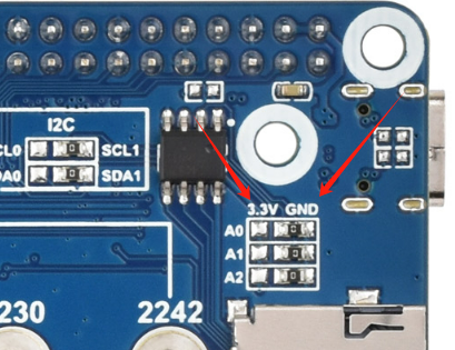
I2C Bus Switching
The I2C bus can be switched through resistors (the switch will switch the EEPROM and the encryption chip together)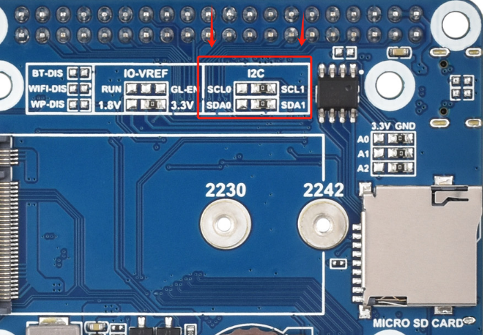
I2C0 (GPIO0,1)
I2C1 (GPIO2,3)
Resources
Datasheets and Schematic Diagram
CM5 Core board datasheet
CM5 Core board 3D
CM5 Core introduction
CM5-IO-BASE-B Schematic diagram
CM5-IO-BASE-B-3D
Related Links
FAQ
Question: Can the old versions of the Raspberry Pi operating system be used with CM5?
CM5 requires the latest version of Raspberry Pi OS Bookworm (2024-11-19 or later).
Support
Monday-Friday (9:30-6:30) Saturday (9:30-5:30)
Email: services01@spotpear.com