- sales/support
Google Chat:---
- sales
+86-0755-88291180
- sales01
sales@spotpear.com
- sales02
dragon_manager@163.com
- support
tech-support@spotpear.com
- CEO-Complaints
zhoujie@spotpear.com
- sales/support
WhatsApp:13246739196
- HOME
- >
- ARTICLES
- >
- Common Moudle
- >
- ESP
ESP32-S3-ETH User Guide
Overview
Introduction
ESP32-S3-GEEK is an Ethernet development board designed based on ESP32-S3R8. It has excellent Wi-Fi and Bluetooth wireless connection functions, has a more reliable and efficient wired Ethernet connection, and supports PoE power supply (PoE version only). The onboard camera interface is compatible with mainstream cameras such as OV2640 and OV5640, which is convenient for image and video capture. The development board also reserves a Pico-compatible interface, supporting some Raspberry Pi Pico expansion boards. Relying on its rich ecosystem and open-source resources, users can quickly and flexibly perform secondary development. It is widely applicable to Internet of Things, image acquisition, smart home, and artificial intelligence projects.
Features
- Based on the high-performance ESP32-S3R8 chip, equipped with an Xtensa 32-bit LX7 dual-core processor, with a main frequency up to 240MHz
- Integrated 512KB SRAM and 384KB ROM, with built-in 8MB PSRAM and 16MB Flash
- Supports 2.4GHz Wi-Fi and Bluetooth 5 (LE), built-in antenna, supports external antenna
- Onboard W5500 Ethernet chip, extending 10/100Mbps network connectivity via SPI interface
- Supports external PoE module for Power over Ethernet (IEEE 802.3af compliant)
- On-board camera interface, compatible with mainstream cameras such as OV2640 and OV5640, suitable for image and video capture
- Onboard USB Type-C port, supporting power supply, debugging and firmware downloading, making development more convenient
- Onboard TF card slot, supporting external TF card storage for pictures and files
- Onboard Pico-compatible interface, providing rich peripheral expansion, with strong compatibility
Onboard Resources
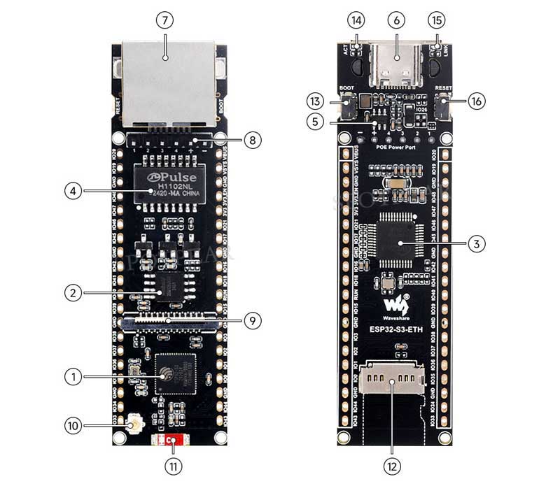
1. ESP32-S3R8 2. W25Q128 3. W5500 4. H1102NLT 5. JW5060 6. USB Type-C interface 7. Ethernet interface | 8. PoE interface 9. Camera interface 10. IPEX Gen 1 antenna interface 11. Ceramic antenna 12. TF card slot |
Interfaces
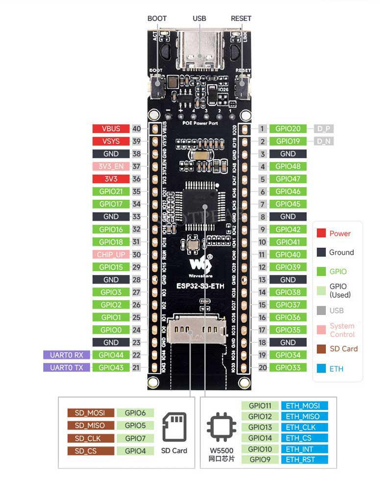
Dimensions
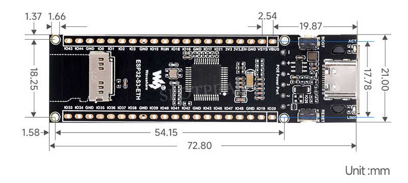
Instructions for Use
Components preparation
- ESP32-S3-ETH x1
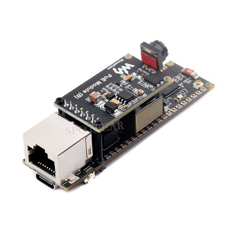
- PoE Module (B) x1
- OV2640 camera x1
- 16GB TF card x 1
- USB cable (Type-A to Type-C) x 1
Working with Arduino
This chapter introduces setting up the Arduino environment, including the Arduino IDE, management of ESP32 boards, installation of related libraries, program compilation and downloading, as well as testing demos. It aims to help users master the development board and facilitate secondary development.
Environment setup
Download and install Arduino IDE
- Click to visit the Arduino official website, select the corresponding system and system bit to download.
- Run the installer and install all by default.
Install Arduino-ESP32
- To use ESP32-related motherboards in Arduino IDE, you must first install the Arduino-ESP32 Board library.
- In some areas, it may not be able to Install online due to network factors, and Install offline is generally recommended.
- To install the Arduino-ESP32 tutorial, please refer to Arduino board manager tutorial
| Board name | Board installation requirements | Version number requirements |
|---|---|---|
| ESP32-S3-ETH | "Install Offline" / "Install Online" | Recommend v2.0.12 |
Install libraries
- When installing Arduino libraries, there are usually two ways to choose from: Install online and Install offline.
For most libraries, users can easily search and install them through the online library manager of the Arduino software. However, some open-source libraries or custom libraries are not synchronized to the Arduino Library Manager, so they cannot be acquired through online searches. In this case, users can only manually install these libraries offline. - For library installation tutorial, please refer to Arduino library manager tutorial
| Library Name | Description | Library Installation Requirements |
|---|---|---|
| Adafruit_NeoPixel | NeoPixel Light Bar Control Library | Install Online or Offline |
| ESP32-BLE-Keyboard | ESP32 Bluetooth Keyboard Library | Install Online or Offline |
| ETHClass | ESP32 Ethernet Library | Install Online or Offline |
Demos
| Demo | Description | Dependency Library |
|---|---|---|
| IO_Test | Basic demo: GPIO pin high and low level control | - |
| RGB_LED | Basic demo: GPIO Pin Control for WS2812 RGB LED | - |
| SD_Card | Basic demo: TF card loading, read and write operations | - |
| WiFi_AP | Basic demo: Set as an AP hotspot to allow other WiFi devices to connect to the Internet | - |
| WiFi_STA | Basic demo: Set to STA mode to access WiFi routing network for networking, and can control the level output of the GPIO port in real time | - |
| BLE_Keyboard | Basic demo: Bluetooth keyboard function demonstration | ESP32-BLE-Keyboard |
| ETH_Web_CAM | Comprehensive demo: Webcam function is implemented via Ethernet connection | ETHClass |
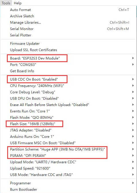
- Arduino project configuration:
IO_Test
Demo description
- This demo demonstrates how to use multiple GPIO pins of the ESP32-S3-ETH module as output control ports. The demo sequentially sets each GPIO pin to high (open) and low (closed) in order, with an interval of 300 milliseconds for each state change. In this way, the sequential switching operation of the GPIO pins can be observed.
Hardware connection
- Connect the board to the computer using a USB cable
Code analysis
1. GPIO pin configuration: The demo first defines the 25 GPIO pins and initializes them into output mode in the setup() function. All pins are set to low level (off state) at the beginning.
#define NUM_GPIO 25

// Define GPIO pins
const int gpio_pin[NUM_GPIO] = {21, 17, 16, 18, 15, 3, 2, 1, 0, 44, 43, 33, 34, 35, 36, 37, 38, 39, 40, 41, 42, 45, 46, 47, 48};
2. GPIO control loop:
- In the
loop()function, the demo will turn on each GPIO pin in turn (set to high) for a delay of 300 milliseconds, and then turn off the pin (set to low). - This process will be repeated constantly.
3. Print Output: The demo outputs the status information of each GPIO pin through the USB port, indicating whether the pin is in a high voltage level (on) or a low voltage level (off) state.
void loop() {
  // Turn on each GPIO one by one
  for (current_gpio = 0; current_gpio < NUM_GPIO; current_gpio++) {
      digitalWrite(gpio_pin[current_gpio], HIGH); // Set GPIO pin to HIGH (turn on)
      printf("GPIO %d set to HIGH.\n", gpio_pin[current_gpio]); // Print GPIO state
      delay(300); // Delay for 300ms
  }

  // Turn off each GPIO one by one
  for (current_gpio = 0; current_gpio < NUM_GPIO; current_gpio++) {
      digitalWrite(gpio_pin[current_gpio], LOW); // Set GPIO pin to LOW (turn off)
      printf("GPIO %d set to LOW.\n", gpio_pin[current_gpio]); // Print GPIO state
      delay(300); // Delay for 300ms
}Running Result
After the demo is flashed, the running result of the device is as follows:
- ESP32-S3-ETH will control 25 GPIO pins in turn. The program switches the HIGH and LOW states on each GPIO pin and outputs the state changes to the monitoring window via USB.
The low level of the output is 0V, and the high level is the operating voltage of the current board. Since the operating voltage of ESP32-S3 is 3.3V, the high level is 3.3V. - Open the serial port monitoring window of the Arduino IDE, and you can observe the state switching of each GPIO pin, as shown in the following figure:

RGB_LED
【Demo description】
This program uses GPIO21 to control a WS2812 RGB LED and demonstrates various lighting effects, including single-color fill (Color Wipe), rainbow gradient (Rainbow), and theater chase effect (Theater Chase).
【Hardware Connection】
Connect the board to your computer using a USB cable.
【Code Analysis】
1. GPIO Pin Configuration: The program first defines the RGB LED control pin as a GPIO pin and performs the following steps in the **`setup` function**:
- Initialize the NeoPixel RGB LED:
- Use `strip.begin()` to enable LED control functionality.
- Set the LED brightness to 50% using `strip.setBrightness(50)`.
- Call `strip.show()` to initialize the LED in the OFF state.
- Configure an additional indicator LED (LED1) as an output and turn it on using `digitalWrite(LED1, HIGH)`.
#define PIN 21           // Pin connected to WS2812 RGB LED
#define LED1 -1          // GPIO for an additional LED (optional)

Adafruit_NeoPixel strip = Adafruit_NeoPixel(60, PIN, NEO_GRB + NEO_KHZ800);

void setup() {
  #if defined (__AVR_ATtiny85__)
    if (F_CPU == 16000000) clock_prescale_set(clock_div_1);
  #endif

  strip.begin();
  strip.setBrightness(50);
  strip.show();

  pinMode(LED1, OUTPUT);
  digitalWrite(LED1, HIGH);  // Turn on the additional LED
}
【Running Result】
- Color Wipe: The RGB LED sequentially displays red, green, and blue, holding each color for a specified duration.
- Theater Chase: Dynamic chase effects with white, red, and blue colors. The LED displays the colors in a cyclic blinking pattern.

SD_Card
Demo description
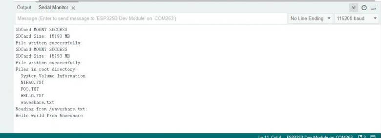
- This program demonstrates how to operate a TF card on the ESP32-S3-ETH module, including initializing the TF card, creating and writing files, listing files in the directory, and reading file content. The program will create a file named “waveshare.txt“, write the text "Hello world from Waveshare", list all the file information in the root directory of the TF card, and finally read the contents of the "waveshare.txt" file and print it to the serial monitor.
Hardware connection
| SPI interface | ESP32-S3-ETH |
|---|---|
| CS (SS) | GPIO4 |
| DI (MOSI) | GPIO6 |
| DO (MISO) | GPIO5 |
| SCK (SCLK) | GPIO7 |
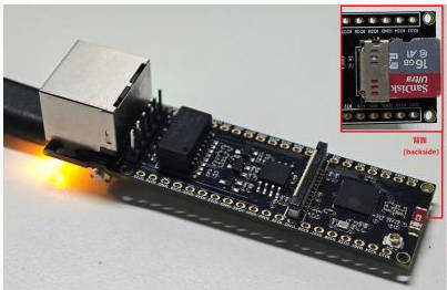
- Install a TF card on the board (a TF card below 16GB is recommended) and connect the board to the computer using a USB cable
Code analysis
1. setup()
- Initialize serial port communication and the TF card.
- Initialize the SPI bus of ESP32 via
SPI.begin()and specify the pins used for TF card communication. - Call
SD.begin()to try to mount the TF card, and output card size upon successful connection. - Call three core functions:
writeFileToSD(): Create and write to a file.listFilesOnSD(): Scan and print all files in the root directory of the TF card.readFileFromSD(): Opens and reads the contents of thewaveshare.txtfile.
2. writeFileToSD()
- The main function is to create or open
waveshare.txtfiles and write the text"Hello world from Waveshare". - After the file write is completed, the file is closed to ensure that the write operation completes correctly.
3. listFilesOnSD()
- Scan all files in the root directory of the TF card and output the file names through the serial port.
- Use
the openNextFile()function to open each file in the directory in turn and print their names, and finally close the root directory file.
4. readFileFromSD(const char *filePath)
- Open and read the file with the specified path, here is
waveshare.txt. - If the file exists, use
file.read()to read the content byte by byte, output the content of the file through the serial port, and finally close the file.
Running Result
After the demo is flashed, the running result of the device is as follows:
- Mount the TF card first, then create and write files, scan and list the root directory files of the TF card, and finally open and read the content of a specific file.
WIFI_AP
Demo description
- This demo configures the ESP32-S3-ETH as a WiFi access point (AP mode), allowing other devices to connect to this WiFi network. The MAC addresses of the connected devices and their assigned IP addresses will be printed on the serial port monitor. This program allows you to learn how to use the ESP32 as an access point and dynamically monitor the information of the devices connected to the access point.
Hardware connection
- Connect the board to the computer using a USB cable
Code analysis
1. setup()
- Initialize serial communication and configure ESP32 as a WiFi access point (AP).
- Set up the AP using
WiFi.softAP()and specify the network name (SSID) as "ESP32-S3-ETH"and the password as "88888888". - Use
WiFi.onEvent()to register a WiFi event handler that handles client connections and disconnections. - Print a confirmation message on the serial port to indicate that the AP initialization was successful.
2. formatMacAddress()
- Convert the MAC address from a byte array format to a readable string format (such as
XX:XX:XX:XX:XX:XX:XX). - Used to display the MAC address of the connected device on the serial port.
3. WiFiEvent()
- Handle WiFi events, such as client connections and disconnections.
- When the device is connected:
- Print the MAC address of the device.
- Add a short delay (500 ms) to ensure DHCP has time to assign IP addresses.
- Call
printDeviceIP()to get and display the assigned IP address.
- When the device is disconnected, print the disconnection information.
4. printDeviceIP(const uint8_t* mac)
- Retrieves and prints the IP address of the connected device based on the MAC address.
- Use the ESP-IDF functions
esp_wifi_ap_get_sta_list()andtcpip_adapter_get_sta_list()to get a list of connected devices. - Traverse through the list of devices, compare MAC addresses to identify target devices.
- If the IP address is valid (not
0.0.0.0), the IP address is printed. Otherwise, it means that DHCP has not assigned an IP address.
5. loop()
- A small delay is included to keep the CPU idle and prevent unnecessary load.
- There are no other operations in the main loop.
Running Result
After the demo is flashed, the running result of the device is as follows:
- The ESP32-S3-ETH module will start a WiFi access point with the network name "ESP32-S3-ETH".
- When the device is connected to the access point, its MAC address and assigned IP address are printed to the serial monitor.
- When the device is disconnected, a disconnect message is also output on the serial port.

WIFI_STA
Demo description
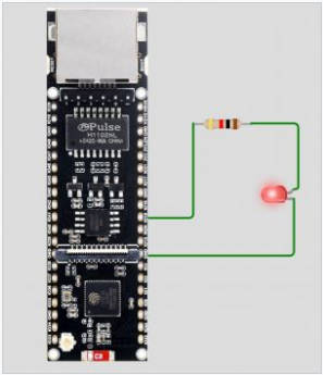
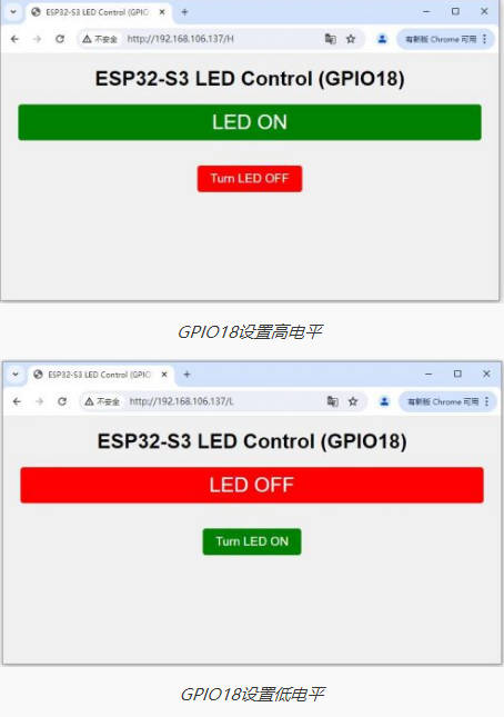
- The demo configures the ESP32-S3 module as a WiFi workstation (STA mode) and sets up a web server to control the LEDs connected to the GPIO18 via a web page. The user can check the current LED status (LED ON or LED OFF) on the web page and toggle the switching status of the LED. Each time the LED status changes, the status information is displayed on the web page and on the serial monitor.
Hardware connection
- Connect the board to the computer using a USB cable

Code analysis
1. setup()
- Function: Initializes system settings, including serial communication, GPIO configuration, WiFi connection, and web server startup.
- Main steps:
- Initialize serial port communication (for debugging output).
- Set GPIO18 as the output and make sure the LED is initially off.
- Connect to a WiFi network and print the IP address on the serial monitor.
- Start the web server and wait for the client to connect.
2. loop()
- Function: Handles client connections and HTTP requests, switches the LED status based on the request content, and generates an HTML page to display the current LED status.
- Main steps:
- Check whether a new client is connected and read the HTTP request.
- Control the high or low level of GPIO18 based on the request path "/H" or "/L" to switch the LED status.
- Generate an HTML page containing the current LED status and switch links, then return it to the client.
- Close the connection with the client, wait for the next connection request.
Running Result
After the demo is flashed, the running result of the device is as follows:
- After the module is connected to the network, the IP address of the module is printed out in the monitoring window
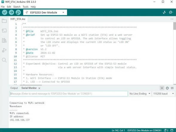
- Open a web browser and enter the corresponding IP, you can control the high and low level status of the GPIO18 pin in real time, and the corresponding serial port monitoring window will also print out the return status value of H or L in real time.
BLE_Keyboard
ETH_Web_CAM
Demo description
| Camera interface | ESP32-S3-ETH GPIO |
|---|---|
| VSYNC | GPIO1 |
| HREF | GPIO2 |
| XCLK | GPIO3 |
| PCLK | GPIO39 |
| SIOD (SDA) | GPIO48 |
| SIOC (SCL) | GPIO47 |
| D7 | GPIO18 |
| D6 | GPIO15 |
| D5 | GPIO38 |
| D4 | GPIO40 |
| D3 | GPIO42 |
| D2 | GPIO46 |
| D1 | GPIO45 |
| D0 | GPIO41 |
| Network port interface | ESP32-S3-ETH GPIO |
|---|---|
| MISO | GPIO12 |
| MOSI | GPIO11 |
| SCLK | GPIO13 |
| CS | GPIO14 |
| RST | GPIO9 |
| INT | GPIO10 |
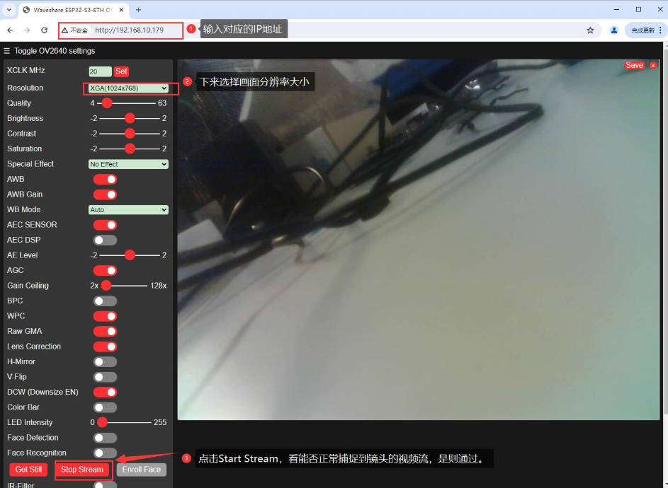
The demo utilizes the ESP32-S3-ETH module for Ethernet connectivity and, in conjunction with a camera module, implements image acquisition and streaming. The demo will configure the camera pins and start the camera server, so that the user can access the camera content in real time via Ethernet. During initialization, the demo sets various parameters of the camera, including resolution, pixel format, etc., and monitors the status of the Ethernet connection through network events.
Hardware connection
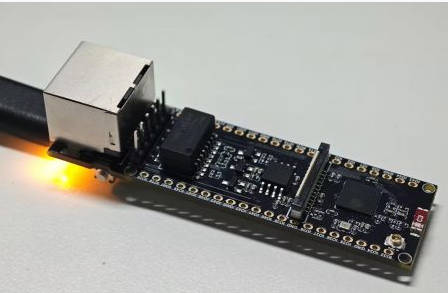
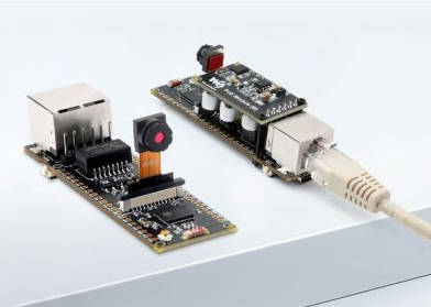
- Refer to the figure below to connect the hardware (if you don't need PoE power supply, there is no need to connect the PoE module)
Code analysis
1. setup()
- Function: Configure serial port debugging and initialize the Ethernet connection, and set the camera control pins.
- Start Ethernet according to different ESP32 configurations through conditional compilation:
- SPI mode: On non-ESP32 devices, use "ETH.beginSPI()" to start Ethernet.
- After waiting for the Ethernet connection to be successful, configure the camera parameters and start the camera server for external access.
- Camera configuration: Configure various parameters of the camera through the "camera_config_t" structure, including:
- Image resolution, format (JPEG or RGB565), XCLK frequency, frame buffer, etc.
- If PSRAM is detected, higher JPEG quality and frame buffer settings will be used to improve image quality.
2. startCameraServer()
- Start the camera server so that the user can access the camera content through the network.
3. Event handling function WiFiEvent(WiFiEvent_t event)
- Function: Used to monitor the status of the Ethernet connection and output debugging information when an event occurs.
- Connection event : When Ethernet is started, connected, or disconnected, status information is output.
- Get IP address event: When an IP address is successfully obtained, the MAC address, IPv4 address, full-duplex status, link speed, and gateway IP address of the device are printed.
Running Result
- After startup, the ESP32-S3 initializes the Ethernet and outputs the connection status.
- After the camera is successfully initialized, the server will start to provide real-time image transmission services, and users can connect to the camera server through Ethernet to view real-time video.
- If the connection is disconnected or the camera initialization fails, the demo will output an error message on the serial monitor.
Flash Firmware Flashing and Erasing
- The current demo provides test firmware, which can be used to test whether the onboard device functions properly by directly flashing the test firmware
Resources
Schematic diagram
Demos
Datasheets
ESP32-S3
Other components
Software tools
Arduino
Flash Download Tool
Other resource link
FAQ
Long press the BOOT button, press RESET at the same time, then release RESET, then release the BOOT button, at this time the module can enter the download mode, which can solve most of the problems that can not be downloaded.
As shown in the figure below, the default weld is a vertical 0R resistor. If you want to switch to an external antenna, you need to re-solder the 0R resistor to a horizontal position: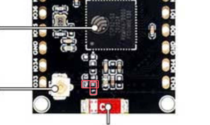
Support
[Tutorial Navigation]
- Overview
- Instructions for Use
- Working with Arduino
- Flash Firmware Flashing and Erasing
- Resources
- FAQ
- Question: After the module downloads the demo and re-downloads it, why sometimes it can't connect to the serial port or the flashing fails?
- Question: How to switch to the external antenna for IPEX 1 generation?
- Support


