- sales/support
Google Chat:---
- sales
+86-0755-88291180
- sales01
sales@spotpear.com
- sales02
dragon_manager@163.com
- support
tech-support@spotpear.com
- CEO-Complaints
zhoujie@spotpear.com
- Only Tech-Support
WhatsApp:13246739196
- Purchase/Shipping/Refund
WhatsApp:13424403025
- HOME
- >
- ARTICLES
- >
- Common Moudle
- >
- UART Module
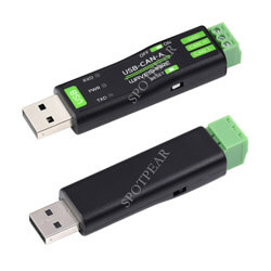
USB-CAN-A User Guide
Features
- Supports CAN2.0A (standard frame) and CAN2.0B (extended frame)
- CAN baud rate is configurable in the range of 5Kbps-1Mbps
- Supports 4 working modes: normal mode, loopback mode, silent mode, silent loopback mode
- Supports multiple CAN data sending modes: single frame, multiple frames, manually, regular and cyclic sending
- Supports multiple CAN data receiving modes: can be configured to only receive data from a certain ID, or specify an ID to automatically answer the configured data
- Data can be saved as TXT or Excel
- Supports CAN bus detection for status checking
- Sending/receiving CAN data with a time scale, allows sequentially displaying
- Baud rate of the USB virtual COM port is configurable in the range of 9600 ~ 2000000bps (2000000bps by default)
- Supports set working parameters by configuration software or serial command, can be saved after power off
- Adopts STM32 chip solution, stable and reliable communication
- Onboard TVS (Transient Voltage Suppressor), effectively suppresses surge voltage and transient spike voltage in the circuit
- Comes with master computer software for Windows system, easy to use
- Easy secondary development, just need to modify the sending and receiving commands
Primary Function
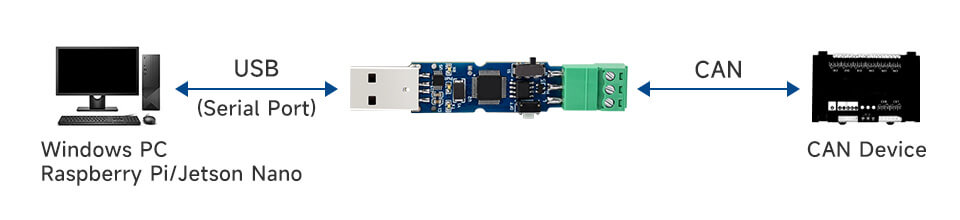
Using in Windows System
Install USB Driver
- Download CH341SER.zip, double click "CH341SER.EXE" file, and click to install. Click "Finish" after installation is complete.
How to Use USB Config Tool
Open CAN config tool:
- The tool does not need to be installed, you can open "USB-CAN.exe" after downloading and unzipping.
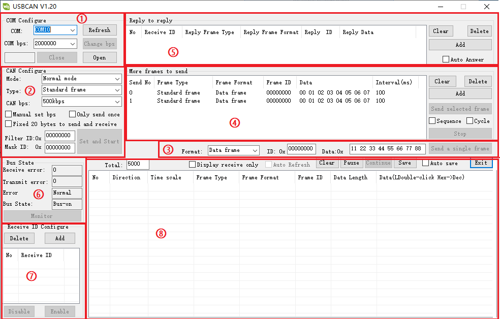
Config functions description:
① Port Setting:
After inserting the "USB To CAN" into the computer, the COM port of the computer can be found automatically. Choose the port, and it can be opened or closed (similar to the serial port assistant). The baud rate is 2000000bps by default.
If you want to modify the baud rate, you can refer to the following content:
1. Connect to the converter by a USB cable and pay attention to the flickering of TX and RX indicators at the same time:
Flash 1 time, the baud rate of the corresponding serial port is 2000000bps
Flash 2 times, the baud rate of the corresponding serial port is 1228800bps
Flash 3 times, the baud rate of the corresponding serial port is 115200bps
Flash 4 times, the baud rate of the corresponding serial port is 38400bps
Flash 5 times, the baud rate of the corresponding serial port is 19200bps
Flash 6 times, the baud rate of the corresponding serial port is 9600bps
2. Open the software and choose the corresponding COM port and baud rate. Click the "Open" button. (If the TX and RX indicators flash 1 time when the converter is connected to the USB cable and powered on, we should choose the baud rate of 2000000bps.)
3. Click the "Open" button.
4. Click the Change Baud Rate button, and a dialog box will pop up. After we select the baud rate we are going to set in the baud rate combo box, click Change; if you do not want to change, click the Cancel button.
5. For example, if we want to set the baud rate as 9600bps:
- Set "9600" in the baud rate combo box.
- Click "Change", and pay attention to the RX and TX indicators.
- The indicators will flash 6 times corresponding to the baud rate of 9600.
- As the baud rate is changed, you need to close the port and open it again after selecting the changed baud rate.
6. Click the "Close" button.
7. Set the baud rate as the changed one.
8. Click the "Open" button again.
② CAN Setting
The operating modes include: normal, loopback, silent, and silent loopback modes.
- Normal mode: the normal operating mode of CAN can send and receive the data to the bus.
- Loopback mode: the data can be sent to the CAN bus, give feedback to the internal reception area, and rejects the data from the external pin. This mode is for self-testing.
- Silent loopback mode: this mode is for "hot testing", which is self-testing. It can be tested like the loopback mode but does not affect the CAN bus system.
- Frame type: standard frame (CAN2.0A 11-bit ID), extended frame (CAN2.0B 29-bit ID)
- CAN baud rate: you can directly choose the common ones for CAN communication: 1M, 800K, 500K, 400K, 250K, 200K, 125K, 100K, 50K, 20K, 10K, 5K. *You can choose one if the above baud rate that can be directly set is different from your CAN device.
- Filter ID and Mask ID: Both are hexadecimal data, the lower 11 bits of filter ID and mask ID are valid in a standard frame (range: 0x00000000~0x000007ff), and the lower 29 bits of filter ID and mask ID in the extended frame are valid (range 0x00000000~0x1fffffff).
- Fixed 20-byte transceiver: There are 2 conversion protocols inside the CAN converter, one is a communication protocol that can be lengthened, and the other is a fixed 20-byte communication protocol. If selected, it will be a fixed 20-byte communication protocol. After selecting the variable protocol communication, a custom baud rate dialog box will pop up. The calculation formula of the CAN baud rate at the top, and set the phase buffer 1, phase buffer 2, and prescaler at the same time.
- Disable automatic message retransmission: CAN communication is generally automatically retransmitted if the transmission is unsuccessful. If the data is sent cyclically, you can set it to disable the automatic retransmission of the message. Click Set and start CAN communication.
③ Send single-frame data field:
The frame format includes data frame and remote frame, the frame ID is hexadecimal data, the frame ID range for the standard frame is 0x00000000~0x000007fff, and the frame ID range for the extended frame is 0x00000000~0x1fffffff. The data sent is also hexadecimal data, the data in the figure are 0x11 0x22 0x33 0x44 0x55 0x66 0x77 0x88. Click the send single frame button to send the frame data to the CAN bus.
④ Multi-frame sending data field:
- Add: you can add one sending frame data under the multi-frame sending data area.
- Delete: delete the chosen line.
- Clear: clear all the data in the multi-frame sending data area.
- Interval time: the interval sending time of two consecutive frames in the multi-frame sending area (milliseconds)
- Send the chosen frame: it will send the chosen row in this area.
- Sequence: it will turn to the next frame after clicking to send the chosen row.
- Cycle: it will send the chosen frame in the cycle after clicking to send the data.
- Stop: cancel the command of sending the multiple frames.
⑤ Auto Response field
- Add: add one auto-sending frame data in the Auto Response Area.
- Delete: delete the chosen row.
- Clear: clear all the data in this area.
- Auto response: it will automatically reply to the corresponding frame ID and data after receiving the ID.
⑥ CAN Bus Status
Mainly used to check the CAN communication status of the USB to CAN device.
⑦ Configure the Accept ID field
- Add button: an auto-response will be added under the selected row in the configuration acceptance area.
- Delete button: the selected row will be deleted.
- Enable button: After clicking this button, the converter will only upload the ID set in the configuration acceptance ID area, and other IDs will not be uploaded to the computer.
- Disable button: After clicking this button, the converter will upload all ID data to the computer.
⑧ Send and receive data display field:
- Clear: clear all data on the display for sending and receiving data.
- Pause: pause to display other data in the send and receive display area.
- Continue: continue to display sending and receiving data.
- Save: you can save the data in the sending and receiving data buffer in two formats, excel or text.
- Do not display the sending frame: only the received data can be displayed in the sending and receiving data area.
- Automatic refresh: when only the accepted data is displayed, you can choose to automatically refresh. At this time, the data is refreshed in real-time instead of continuously increasing the column display. This function can summarize the ID data summarized by CAN and select any row.
Hardware Test
2-CH CAN FD HAT Connection Test
- Connect USB-CAN-A and the 2-CH CAN FD HAT with Dupont cables. Connect A-->A and B-->B, and connect the USB terminal of USB-CAN-A to the computer USB port:
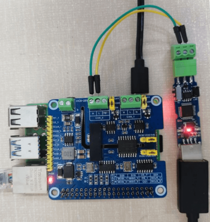
- Open USB-CAN debug tool on the computer and its default baud rate is 2M. Open the corresponding port, select the normal mode, the standard frame and the corresponding rate of the demo is 1Mbps (USB-CAN-A supports 1M). Set and boot it, 2-CH CAN FD HAT and USB-CAN-A can realize the data transmission.
As shown below: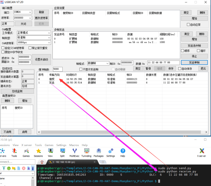
USB-CAN-B Connection Test
- Connect USB-CAN-A and 2-CH CAN FD HAT by H-L and L-L with Dupont cables. Then, turn on their 120 Ohm resistive switches.
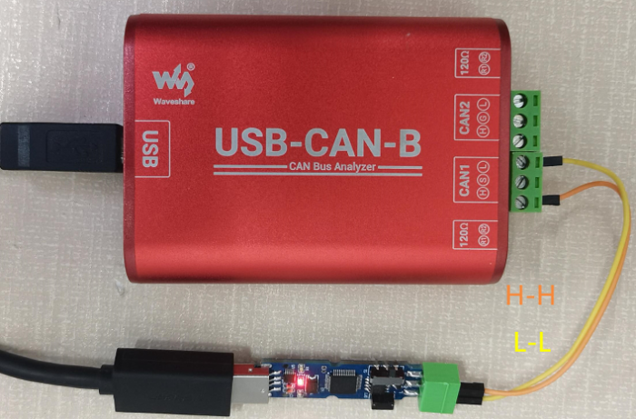
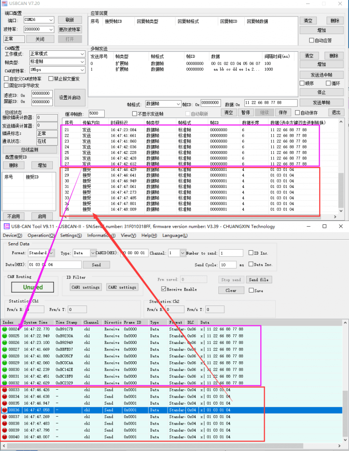
- Open the corresponding config tool, USB-CAN-A sends data, and USB-CAN-B can receive it; USB-CAN-B sends data, and USB-CAN-A can receive it too. That means the test is successful.
Using in Linux System
Hardware Test
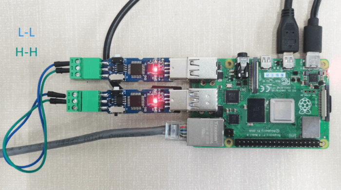
- The L and H of the 2 USB-CAN-A are connected correspondingly, and the 120-ohm resistance switch of the two is turned on (the switch is moved to the side near the green terminal), and the USB ends are respectively connected to the USB ports of the Raspberry Pi. The hardware connection is shown below:
Demo Test
- Copy the following commands to the terminal of the Raspberry Pi.
wget https://www.waveshare.com/w/upload/7/72/USB-CAN-A.zip
sudo apt-get install unzip
unzip USB-CAN-A.zip
cd USB-CAN-A
sudo make clean
sudo make
- Enter the following commands in the terminal interface.
./canusb -t -d /dev/ttyUSB0 -s 1000000 -t
- Open another terminal interface and run:
./canusb -d /dev/ttyUSB1 -s 1000000 -t -i 5 -j BEEE
- One USB-CAN-A (ttyUSB0) sends data, and the other USB-CAN-A (ttyUSB1) receives the corresponding data. The effect is as follows: