- sales/support
Google Chat:---
- sales
+86-0755-88291180
- sales01
sales@spotpear.com
- sales02
dragon_manager@163.com
- support
tech-support@spotpear.com
- CEO-Complaints
zhoujie@spotpear.com
- Only Tech-Support
WhatsApp:13246739196
- Purchase/Shipping/Refund
WhatsApp:13424403025
- HOME
- >
- ARTICLES
- >
- Common Moudle
- >
- Sensors
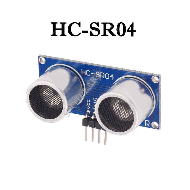
HC-SR04 User Guide
Arduino connects ultrasonic sensor for distance measurement
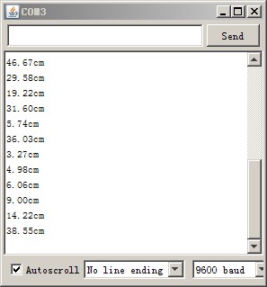
Ultrasonic sensors are suitable for static distance measurement of large flat surfaces. The range of ordinary ultrasonic sensors is about 2cm-450cm, and the resolution is 3mm (the test environment is not so good, and the personal measurement is relatively stable. The distance is about 10cm-2m. If this distance is exceeded, accidental inaccuracies often occur. Of course not Eliminate technical issues.)
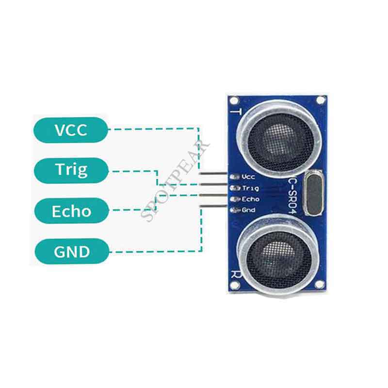
The test object is the SRF-04 ultrasonic sensor, which has four pins: 5v power supply pin (Vcc), trigger control terminal (Trig), receiving terminal (Echo), and ground terminal (GND)
The working principle of the module:
IO trigger ranging to at least 10us high signal;
module automatically sends eight 40kHz square wave, automatically detect whether a signal return;
a signal to return to a high IO output, high duration of the ultrasonic time from launch to return.
Test distance = (time high * speed of sound (340M / S)) / 2;
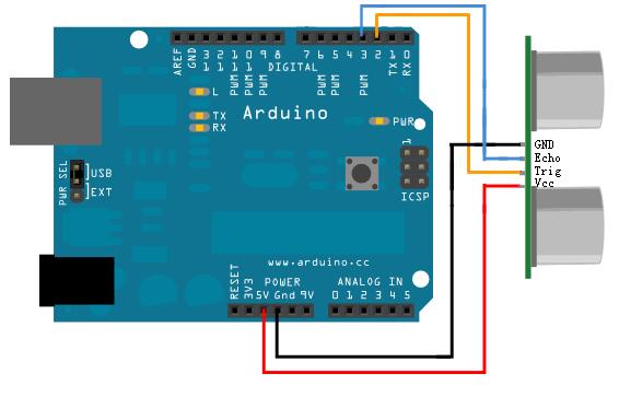
Circuit connection method:
Arduino program example: