


- sales/support
Google Chat:---
- sales
+86-0755-88291180
- sales01
sales@spotpear.com
- sales02
dragon_manager@163.com
- support
tech-support@spotpear.com
- CEO-Complaints
zhoujie@spotpear.com
- Only Tech-Support
WhatsApp:13246739196
- Purchase/Shipping/Refund
WhatsApp:13424403025
- HOME
- >
- ARTICLES
- >
- Common Moudle
- >
- ESP
ESP32-S3-Touch-AMOLED-2.16 User Guide
Features
- Powered by the ESP32-S3R8 high-performance Xtensa 32-bit LX7 dual-core processor, with a main frequency of up to 240 MHz
- Supports 2.4GHz Wi-Fi (802.11 b/g/n) and Bluetooth 5 (LE) with an onboard antenna
- Built-in 512KB SRAM and 384KB ROM, with stacked 8MB PSRAM and external 16MB Flash
- Features a Type-C interface, enhancing user convenience and device compatibility
- Onboard 2.16inch capacitive touch high-definition AMOLED display, 480 × 480 resolution, 16.7M colors, enabling clear display of color images
- Utilizes an AMOLED screen, offering higher contrast, wider viewing angles, rich colors, and fast response times for superior visual effects, along with advantages such as slim design, low power consumption, and flexibility
- Built-in CO5300 driver chip and CST9220 capacitive touch controller chip, communicating via QSPI and I2C interfaces respectively, minimizing the use of I/O pins
- Equipped with a dual-microphone array for audio algorithms such as noise reduction and echo cancellation, suitable for accurate speech recognition and near-field/far-field wake-up applications
- Onboard QMI8658 6-axis IMU (3-axis accelerometer and 3-axis gyroscope) enables motion posture detection, step counting, and other functions
- Onboard PWR and BOOT side buttons, configurable for custom function development
- Onboard 3.7V MX1.25 lithium battery charge/discharge interface
- The AXP2101 provides an efficient power management solution, supporting multiple configurable output voltages and integrating charging and battery management functions to help extend battery life
Onboard Resources
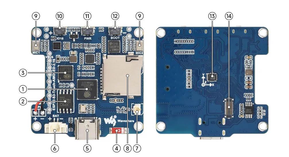
- ESP32-S3R8 Wi-Fi and Bluetooth SoC, up to 240MHz operating frequency, with onboard 8MB PSRAM
- 16MB NOR Flash
- AXP2101 Highly integrated power management chip
- Onboard Chip Antenna Supports 2.4GHz Wi-Fi (802.11 b/g/n) and Bluetooth 5 (LE)
- Type-C Port ESP32‑S3 USB port for programming and log output
- MX1.25 Lithium Battery Header MX1.25 2PIN connector for connecting a 3.7V lithium battery, supports charging and discharging
- IPEX 1 Antenna Connector Can be switched to an external antenna by changing the resistors
- TF Card Slot
- Dual-microphone Design Combined with echo cancellation circuitry for higher quality audio capture
- GPIO 18 Button Supports custom functions
- PWR Power Button Controls power on/off and supports custom functions
- BOOT Button Used for device startup and functional debugging
- QMI8658 6-axis IMU includes a 3-axis gyroscope and a 3-axis accelerometer
- Screen Interface
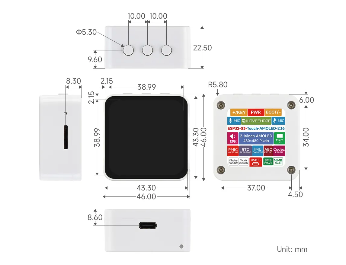
Dimensions
Working with Arduino
This chapter contains the following sections. Please read as needed:
Arduino Getting Started
New to Arduino ESP32 development and looking for a quick start? We have prepared a comprehensive Getting Started Tutorial for you.
- Section 0: Getting to Know ESP32
- Section 1: Installing and Configuring Arduino IDE
- Section 2: Arduino Basics
- Section 3: Digital Output/Input
- Section 4: Analog Input
- Section 5: Pulse Width Modulation (PWM)
- Section 6: Serial Communication (UART)
- Section 7: I2C Communication
- Section 8: SPI Communication
- Section 9: Wi-Fi Basics
- Section 10: Web Server
- Section 11: Bluetooth
- Section 12: LVGL GUI Development
- Section 13: Comprehensive Project
Note: This tutorial uses the ESP32-S3-Zero as a reference example, and all hardware code is based on its pinout. Before you start, we recommend checking the pinout of your development board to ensure the pin configuration is correct.
Setting Up Development Environment
1. Installing and Configuring Arduino IDE
Please refer to the tutorial Installing and Configuring Arduino IDE to download and install the Arduino IDE and add ESP32 support.
2. Installing Libraries
- When installing Arduino libraries, there are typically two methods: Install Online and Install Offline. If the library installation requires Install Offline, you must use the provided library file.
- For most libraries, users can easily search for and install them via the Arduino IDE's online Library Manager. However, some open-source or custom libraries are not synchronized to the Arduino Library Manager and therefore cannot be found through online search. In this case, users can only install these libraries manually via offline methods. You can click this link to download the demo package for the ESP32-S3-Touch-AMOLED-2.16 board from the
Arduinodirectory. TheArduino\librariesdirectory within this package contains all the necessary library files required for this tutorial.
| Library/File Name | Description | Version | Installation Method |
|---|---|---|---|
| GFX Library for Arduino | ST7789 display driver graphics library | v1.6.4 | Install via library manager or manually |
| SensorLib | PCF85063, QMI8658 sensor driver library | v0.3.3 | Install via library manager or manually |
| XPowersLib | AXP2101 driver library | v0.2.6 | Install via library manager or manually |
| lvgl | LVGL display framework | v8.4.0 | Install via library manager or manually |
| Mylibrary | Board pin macro definition | —— | Install manually |
| lv_conf.h | LVGL configuration file | —— | Install manually |
There are strong dependencies between versions of LVGL and its driver libraries. For example, a driver written for LVGL v8 may not be compatible with LVGL v9. To ensure that the examples can be reproduced reliably, it is recommended to use the specific versions listed in the table above. Mixing different versions of libraries may lead to compilation failures or runtime errors.
Installation Steps:
Download the demo package.
Copy all folders (Arduino_DriveBus, GFX_Library_for_Arduino, etc.) in the
Arduino\librariesdirectory to the Arduino library folder.INFOThe path to the Arduino libraries folder is typically:
c:\Users\<username>\Documents\Arduino\libraries.You can also locate it in the Arduino IDE by going to File > Preferences and checking the "Sketchbook location". The libraries folder is the
librariessubfolder within this path.For other installation methods, please refer to: Arduino Library Management Tutorial.
Demo
The Arduino demos are located in the Arduino/examples directory of the demo package.
| Demo | Basic Description | Dependency Library |
|---|---|---|
| 01_HelloWorld | Demonstrates the basic graphics library function and can also be used to test the basic performance of display screens and the display effect of random text | GFX_Library_for_Arduino |
| 02_GFX_AsciiTable | Prints ASCII characters in rows and columns on the screen according to the screen size | GFX_Library_for_Arduino |
| 03_LVGL_AXP2101_ADC_Data | Drives the AXP2101 using the ported XPowersLib to get power-related data | GFX_Library_for_Arduino |
| 04_LVGL_QMI8658_ui | LVGL draws an acceleration line chart | LVGL, SensorLib |
| 05_LVGL_Widgets | LVGL demonstration | LVGL, Arduino_DriveBus, Adafruit_XCA9554 |
| 06_ES7210 | ES7210 driver demo, picking up human voice for detection | —— |
| 07_ES8311 | ES8311 driver example, plays simple audio | —— |
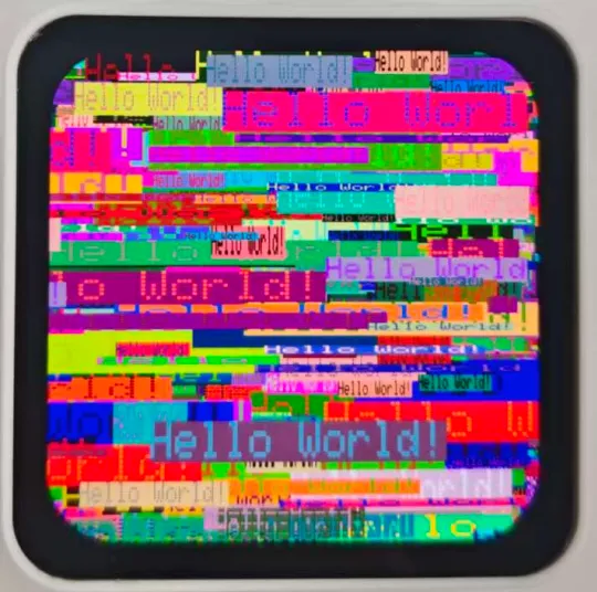
01_HelloWorld
Demo Description
- This demo demonstrates how to control the SH8601 display using the Arduino GFX library, demonstrating basic graphics library functions through dynamically changing text. This code can also be used to test the basic performance of the display and the random text display effects
Hardware Connection
- Connect the development board to the computer
Code Analysis
Display initialization:
if (!gfx->begin()) {
   USBSerial.println("gfx->begin() failed!");
}
Clear the screen and display text:
 gfx->fillScreen(BLACK);
 gfx->setCursor(10, 10);
 gfx->setTextColor(RED);
 gfx->println("Hello World!");
Animated display:
 gfx->setCursor(random(gfx->width()), random(gfx->height()));
 gfx->setTextColor(random(0xffff), random(0xffff));
 gfx->setTextSize(random(6), random(6), random(2));
 gfx->println("Hello World!");
Operation Result
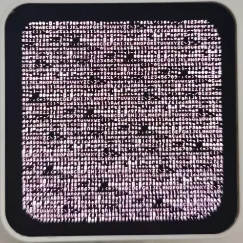
02_GFX_AsciiTable
Demo Description
- This demo shows how to display a basic ASCII character table on the SH8601 display by using the Arduino GFX library on an ESP32. The core function of the code is to initialize the display and print ASCII characters in rows and columns according to the screen size
Hardware Connection
- Connect the development board to the computer
Code Analysis
Create data bus and graphic display objects
- Here a data bus object
busis created for communicating with the display, initialized with specific pin configurations. Then a graphics display objectgfxis created, passing parameters such as the data bus, reset pin, rotation angle, whether it is an IPS panel, and the width and height of the display
 Arduino_DataBus *bus = new Arduino_ESP32QSPI(
    LCD_CS /* CS */, LCD_SCLK /* SCK */, LCD_SDIO0 /* SDIO0 */, LCD_SDIO1 /* SDIO1 */,
    LCD_SDIO2 /* SDIO2 */, LCD_SDIO3 /* SDIO3 */);

 Arduino_GFX *gfx = new Arduino_SH8601(bus, -1 /* RST */,
0 /* rotation */, false /* IPS */, LCD_WIDTH, LCD_HEIGHT);- Here a data bus object
Draw row and column numbers and character table
- First set the text color to green and print the row numbers one by one on the display. Then set the text color to blue and print the column numbers. Next, use a loop to draw each character individually, forming the character table, with each character using white foreground and black background
 gfx->setTextColor(GREEN);
 for (int x = 0; x < numRows; x++) {
    gfx->setCursor(10 + x * 8, 2);
    gfx->print(x, 16);
 }
 gfx->setTextColor(BLUE);
 for (int y = 0; y < numCols; y++) {
    gfx->setCursor(2, 12 + y * 10);
    gfx->print(y, 16);
 }

 char c = 0;
 for (int y = 0; y < numRows; y++) {
    for (int x = 0; x < numCols; x++) {
       gfx->drawChar(10 + x * 8, 12 + y * 10, c++, WHITE, BLACK);
    }
 }
Operation Result
03_LVGL_AXP2101_ADC_Data
Demo Description
- This demo demonstrates power management using the XPowers library under LVGL, and provides PWR custom button control for screen on and off actions
Hardware Connection
- Connect the development board to the computer
Code Analysis
Screen on/off function
  void toggleBacklight() {
  USBSerial.println(backlight_on);
  if (backlight_on) {
      for (int i = 255; i >= 0; i--) {
      gfx->Display_Brightness(i);
      delay(3);
      }
  }else{
      for(int i = 0;i <= 255;i++){
      gfx->Display_Brightness(i);
      delay(3);
      }
  }
  backlight_on = !backlight_on;
  }
Operation Result
04_LVGL_QMI8658_ui
Demo Description
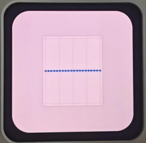
- This demo demonstrates using LVGL for graphical display, communicating with the QMI8658 IMU to obtain accelerometer and gyroscope data
Hardware Connection
- Connect the development board to the computer
Code Analysis
setup: Responsible for initializing various hardware devices and the LVGL graphics library environment- Serial initialization:
USBSerial.begin(115200)prepares for serial debugging - Touch controller initialization: Continuously attempts to initialize the touch controller FT3168. If initialization fails, prints an error message and waits with a delay; prints a success message upon success
- Graphics display initialization: Initializes the graphics display device gfx, sets brightness, and prints LVGL and Arduino version information Then initializes the LVGL, including registering a print callback function for debugging, initializing the display driver and the input device driver. Creates and starts an LVGL timer. Finally creates a label and sets its initial text to "Initializing..."
- Creating a chart: Creates a chart object chart, sets chart properties such as type, range, number of data points, etc., and adds data series for the three axes of acceleration
- Acceleration sensor initialization: Initializes the acceleration sensor qmi, configures accelerometer and gyroscope parameters, enables them, and prints the chip ID and control register information
- Serial initialization:
looplv_timer_handler(): This is an important function in the LVGL graphics library, used to handle various timer events, animation updates, input processing, and other tasks for the graphical interface. Calling this function in each loop ensures the graphical interface runs smoothly and responds to interactions promptly- Reading acceleration sensor data: If acceleration sensor data is ready, reads acceleration data and prints it via the serial port, while updating the chart to display acceleration data. If the gyroscope data is ready, reads the gyroscope data and prints it via the serial port. Finally adds a small delay to increase data polling frequency
Operation Result
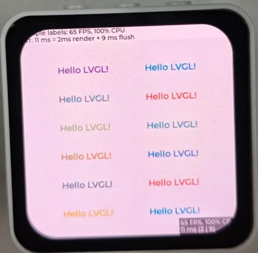
05_LVGL_Widgets
Demo Description
- This example demonstrates LVGL Widgets example. The frame rate can reach 50~60 fps in dynamic states. Optimizing the SH8601 display library can achieve smoother frame rates. This can be compared with scenarios where double buffering and dual acceleration are enabled in the ESP-IDF environment
Hardware Connection
- Connect the development board to the computer
Code Analysis
setup: Responsible for initializing various hardware devices and the LVGL graphics library environment- Serial initialization:
USBSerial.begin(115200)prepares for serial debugging - I2C bus Initialization:
Wire.begin(IIC_SDA, IIC_SCL); initializes I2C bus for communicating with other I2C devices - Expansion chip initialization: Creates and initializes the expansion chip expander, sets pin modes to output, and performs some initial pin state settings
- Touch controller initialization: Continuously attempts to initialize the touch controller FT3168. If initialization fails, prints an error message and waits with a delay; prints a success message upon success
- Graphics display initialization: Initializes the graphics display device gfx, sets brightness, and obtains the width and height of the screen. Then initializes LVGL, including registering a print callback function for debugging, setting the touch controller's power mode to monitoring mode, initializing display driver and input device driver. Creates and starts an LVGL timer. Creates a label and sets its text. Finally calls
lv_demo_widgets()to showcase LVGL example widgets
- Serial initialization:
looplv_timer_handler(): This is an important function in the LVGL graphics library, used to handle various timer events, animation updates, input processing, and other tasks for the graphical interface. Calling this function in each loop ensures the graphical interface runs smoothly and responds to interactions promptlydelay(5): Adds a small delay to avoid excessive CPU resource consumption
Operation Result
06_ES7210
Demo Description
- This demo demonstrates using I2S to drive the ES7210 chip, pick up sounds, and filter out human voice
Hardware Connection
- Connect the development board to the computer
Operation Result
- The device picks up audio directly without showing content on the screen.
07_ES8311
Demo Description
- This demo demonstrates using I2S to drive the ES8311 chip, playing the converted binary audio file
Hardware Connection
- Connect the development board to the computer
Code Analysis
es8311_codec_init: Initializes the ES8311 audio codec- Creates an ES8311 codec handle es_handle
- Configures ES8311 clock parameters, including master clock and sampling clock frequencies, clock polarity, etc.
- Initializes the codec, sets audio resolution to 16-bit
- Configures sampling frequency
- Configures microphone-related parameters, such as turning off the microphone, setting volume and microphone gain
setup: Performs overall initialization settings, including serial port, pins, I2S, and the ES8311 codec- Initializesserial port for debugging output
- Sets a specific pin as output and pulls it high
- Configures the I2S bus, setting pins, operating mode, sample rate, data bit width, channel mode, etc.
- Initializes the I2C bus
- Calls
es8311_codec_initfunction to initialize the ES8311 codec - Plays a pre-defined audio data (canon_pcm) via the I2S bus
Operation Result
ESP-IDF
This chapter contains the following sections. Please read as needed:
ESP-IDF Getting Started
New to ESP32 ESP-IDF development and looking to get started quickly? We have prepared a general Getting Started Tutorial for you.
- Section 1: Environment Setup
- Section 2: Running Examples
- Section 3: Creating a Project
- Section 4: Using Components
- Section 5: Debugging
- Section 6: FreeRTOS
- Section 7: Peripherals
- Section 8: Wi-Fi Programming
- Section 9: BLE Programming
Please Note: This tutorial uses the ESP32-S3-Zero as a teaching example, and all hardware code is based on its pinout. Before you start, it is recommended that you check the pinout of your development board to ensure the pin configuration is correct.
Setting Up Development Environment
For the ESP32-S3-Touch-AMOLED-2.16 development board, ESP-IDF V5.5 or above is required.
The following guide uses Windows as an example, demonstrating development using VS Code + the ESP-IDF extension. macOS and Linux users should refer to the official documentation.
Install the ESP-IDF Development Environment
Download the installation manager from the ESP-IDF Installation Manager page. This is Espressif's latest cross-platform installer. The following steps demonstrate how to use its offline installation feature.
Click the Offline Installer tab on the page, then select Windows as the operating system and choose your desired version from the filter bar.
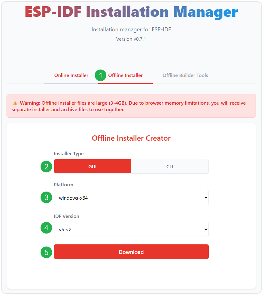
After confirming your selection, click the download button. The browser will automatically download two files: the ESP-IDF Offline Package (.zst) and the ESP-IDF Installer (.exe).
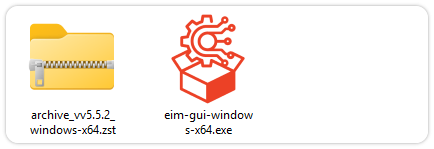
Please wait for both files to finish downloading.
Once the download is complete, double-click to run the ESP-IDF Installer (eim-gui-windows-x64.exe).
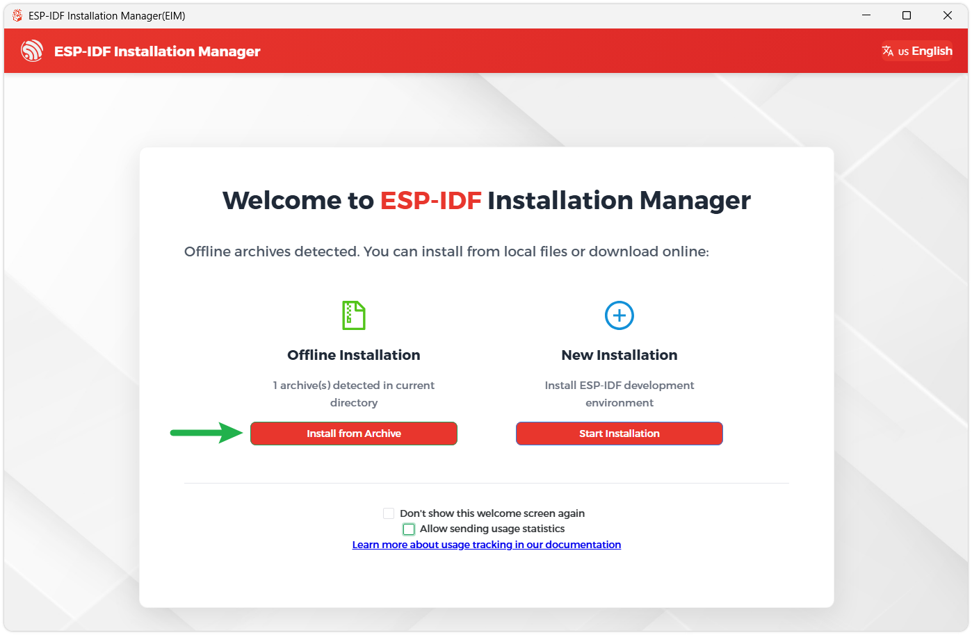
The installer will automatically detect if the offline package exists in the same directory. Click Install from archive.
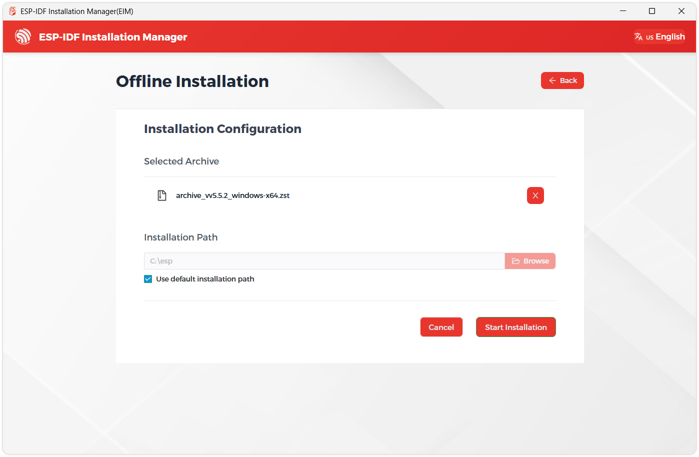
Next, select the installation path. We recommend using the default path. If you need to customize it, ensure the path does not contain Chinese characters or spaces. Click Start installation to proceed.
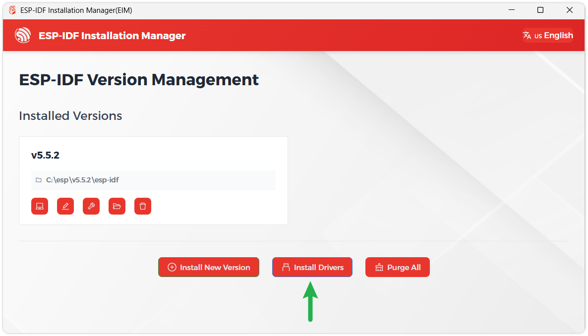
When you see the following screen, the ESP-IDF installation is successful.
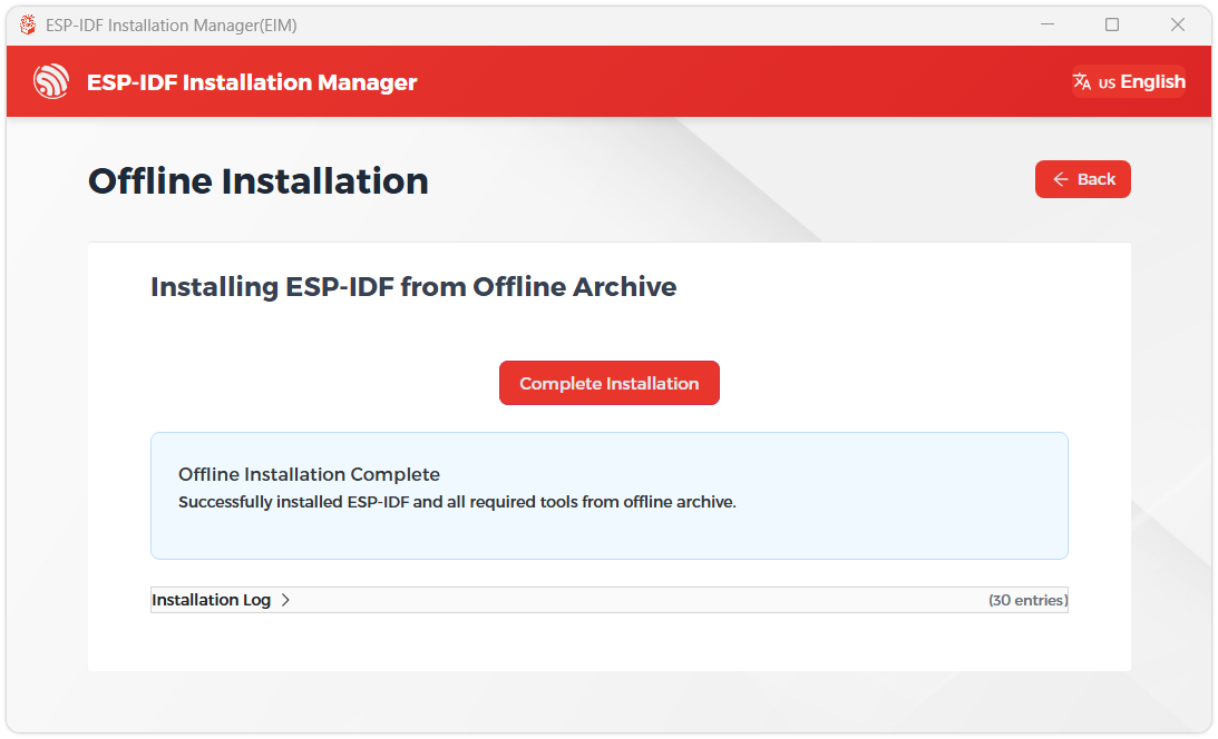
We recommend installing the drivers as well. Click Finish installation, then select Install driver.
Install Visual Studio Code and the ESP-IDF Extension
Download and install Visual Studio Code.
During installation, it is recommended to check Add "Open with Code" action to Windows Explorer file context menu to facilitate opening project folders quickly.
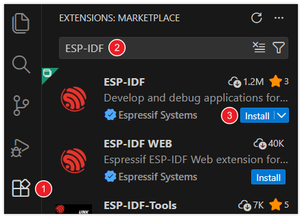
In VS Code, click the Extensions icon
 in the Activity Bar on the side (or use the shortcut Ctrl + Shift + X) to open the Extensions view.
Enter ESP-IDF in the search box, locate the ESP-IDF extension, and click Install.
For ESP-IDF extension versions ≥ 2.0, the extension will automatically detect and recognize the ESP-IDF environment installed in the previous steps, requiring no manual configuration.
Demo
The ESP-IDF demos are located in the ESP-IDF directory of the demo package.
| Demo | Basic Description |
|---|---|
| 01_AXP2101 | Gets power-related data by driving the AXP2101 via the ported XPowersLib |
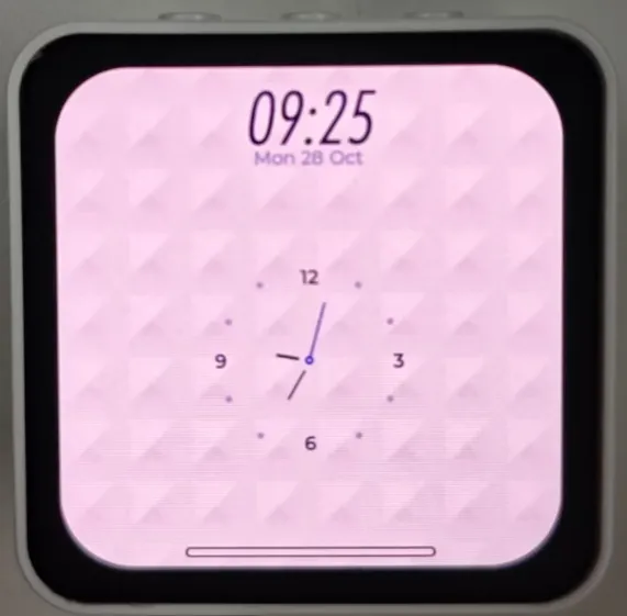
| 02_lvgl_demo_v9 | LVGL Demonstration |
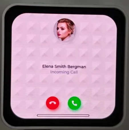
| 03_esp-brookesia | Demonstrates a complete phone-style UI system, including status bar, navigation bar, app launcher, and gesture interaction components |
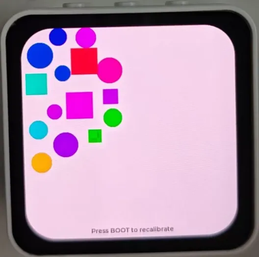
| 04_Immersive_block | Uses the QMI8658 six-axis sensor to collect acceleration data, driving randomly generated geometric shapes rendered by the LVGL graphics library to move in sync with device tilt |
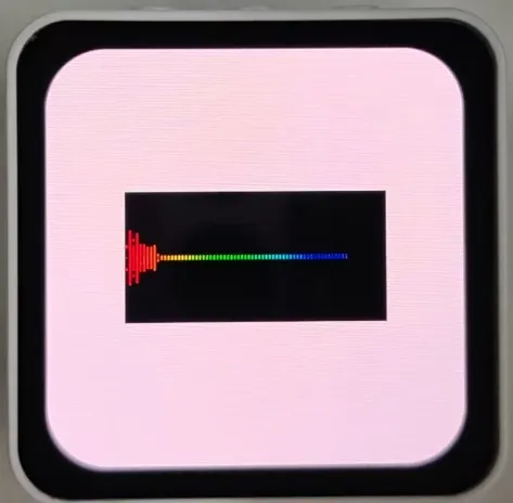
| 05_Spec_Analyzer | Showcases a real-time audio spectrum visualization analyzer, presenting audio frequency distribution intuitively via 64 colored symmetrical spectrum bars with peak tracking |
01_AXP2101
Demo Description
- This demo demonstrates porting XPowersLib in ESP-IDF, and driving AXP2101 to obtain power-related data through the ported XPowersLib
Hardware Connection
- Connect the development board to the computer
Code Analysis
i2c_init: Initializes the I2C master device, preparing it for communication with other devices (e.g., the PMU)- Configures I2C parameters, including setting the master device mode, specifying the SDA and SCL pins, enabling the pull-up resistor, and determining the clock frequency
- Installs the I2C driver to apply the configuration to the actual hardware
pmu_register_read: Reads a series of byte data from a specific register of the PMU- Performs parameter checks to ensure the incoming parameters are valid and avoid invalid read operations
- Performs I2C operations in two steps, first sends the register address to read, then reads the data During the reading process, different processing is carried out according to the length of bytes to be read to ensure accurate reading of the data. At the same time, handles error cases in the I2C communication process and returns the corresponding status code so that the upper-layer code can determine if the read operation is successful
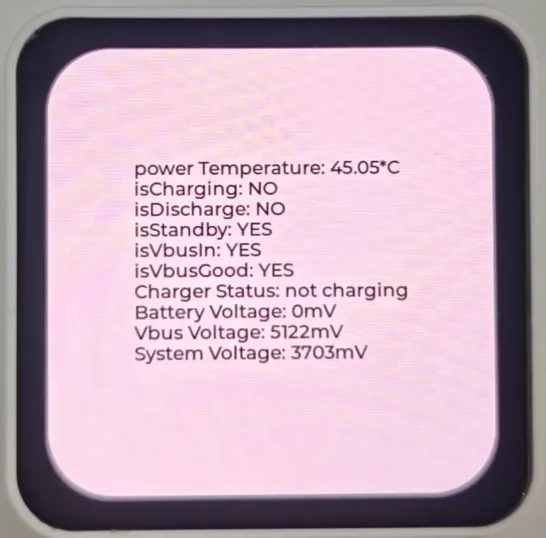
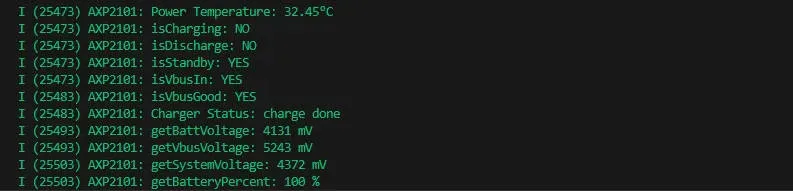
Operation Result
- This demo will not light up the screen
- The serial port monitor displays the parameters: chip temperature, charging state, discharging state, standby state, Vbus connection, Vbus condition, charger status, battery voltage, Vbus voltage, system voltage, battery percentage
02_lvgl_demo_v9
Demo Description
- This demo runs the LVGL V9 demo program
Hardware Connection
- Connect the development board to the computer
Operation Result
03_esp-brookesia
Demo Description
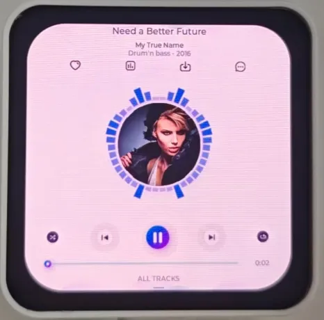
- This example demonstrates a complete phone-style UI system, including components such as a status bar, navigation bar, app launcher, and gesture interaction
Hardware Connection
- Connect the development board to the computer
Operation Result
   |
|---|
04_Immersive_block
Demo Description
- This example uses the QMI8658 six-axis sensor to collect acceleration data, driving randomly generated geometric shapes rendered by the LVGL graphics library to move in sync with device tilt
Hardware Connection
- Connect the development board to the computer
Code Analysis
generate_random_shapes(): Generates graphics randomly- Initializes the random seed (based on system time) and resets the shape count
- Loops to attempt generating shapes, up to 100 attempts to find a valid position (not overlapping with existing shapes)
- Valid position criteria: The shape's center is within the screen boundaries and does not overlap with any previously generated shape
- For a valid position: Updates the LVGL object position (
lv_obj_set_pos) and stores it in the shapes array - For an invalid position: Deletes the LVGL shape object to avoid memory leaks
perform_level_calibration(): Core function for horizontal calibration- Collects 200 acceleration samples, calculates the average value for X/Y axes as the bias values (
accel_bias_x/y) - Detects sample fluctuation range (if the range for X/Y axes is greater than 0.1, calibration is considered unstable and a retry is triggered)
- After calibration is complete, sets the
calibration_doneflag and prints the bias information
- Collects 200 acceleration samples, calculates the average value for X/Y axes as the bias values (
Operation Result
05_Spec_Analyzer
Demo Description
- This example showcases a real-time audio spectrum visualization analyzer. It intuitively presents audio frequency distribution via 64 colored symmetrical spectrum bars with peak tracking
Hardware Connection
- Connect the development board to the computer
Code Analysis
timer_cb: LVGL timer callback function, responsible for spectrum visualization rendering- Canvas and Layer Initialization: Gets the canvas object, initializes an LVGL layer (layer rendering improves refresh efficiency and prevents flickering), and clears the screen (black background)
- Basic Parameter Calculation: Calculates spectrum bar width (canvas width / 64), canvas center Y coordinate (for symmetrical drawing), and spectrum bar gap
- Iterates to render 64 spectrum bars
- Layer Rendering Completion: Calls
lv_canvas_finish_layerto commit the layer rendering and updates the canvas display
lv_example_canvas_10: Canvas initialization- Static Draw Buffer Definition: Uses
LV_DRAW_BUF_DEFINE_STATICto define a 300×150 pixel RGB565 format draw buffer - Canvas Creation: Creates an LVGL canvas object, sets its size and centers it, and binds the static draw buffer
- Timer Creation: Creates a 33ms timer, binds the
timer_cbcallback function, and passes the canvas object as user data to enable timed rendering
- Static Draw Buffer Definition: Uses
Operation Result
XiaoZhi AI Application Tutorial
XiaozhiAI (XiaoZhi AI) is an open-source AI voice chatbot project based on the ESP32 development board, aiming to bring the general intelligence of large language models (LLMs) to edge devices. It provides a software-hardware integrated solution supporting full-duplex voice conversations and IoT device control, dedicated to assisting developers in building highly customized physical AI agents quickly and at low cost.
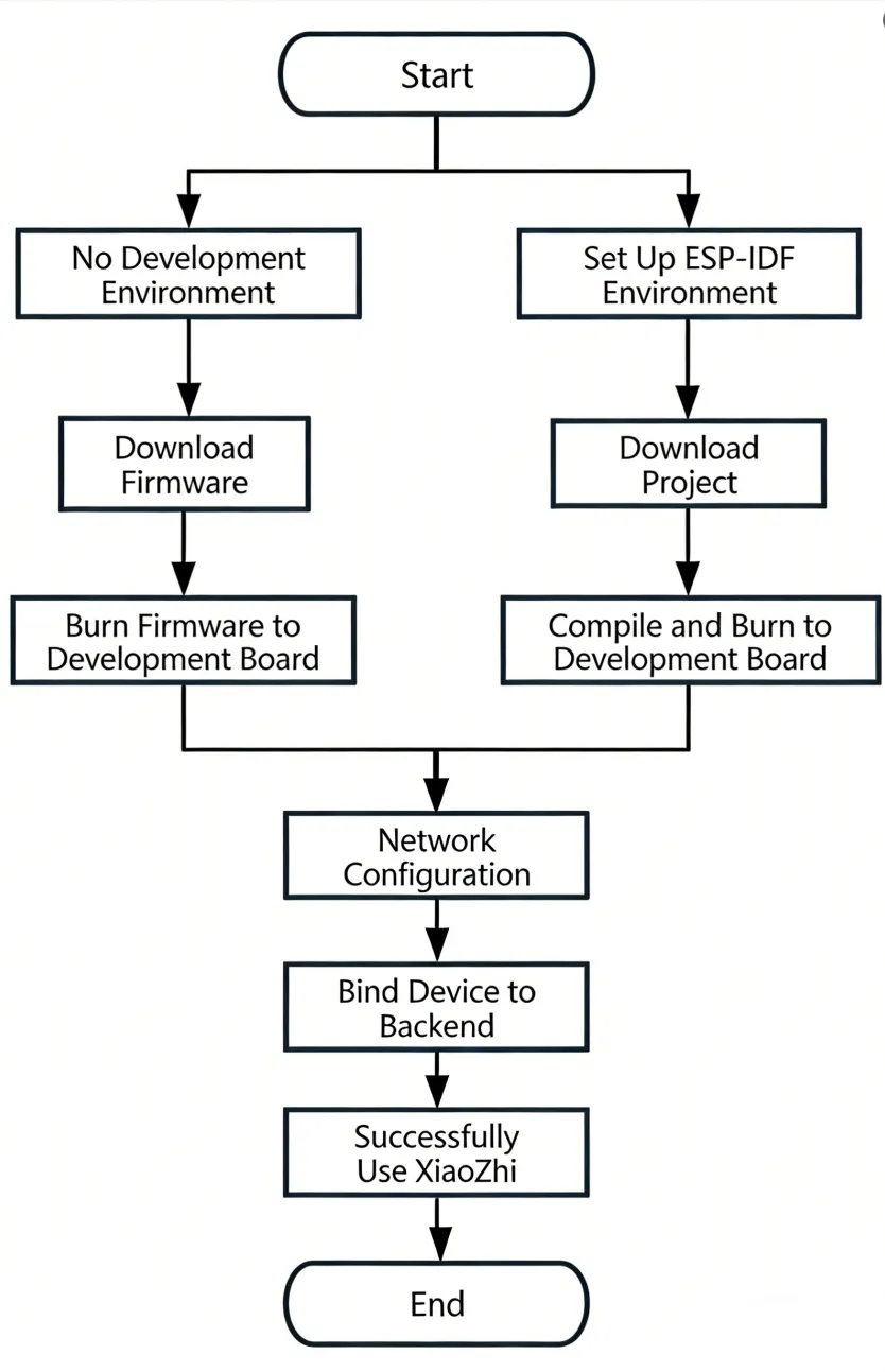
This article demonstrates how to flash firmware for Waveshare ESP32 development boards that support XiaoZhi AI, covering two methods: flashing without a development environment (directly flashing precompiled firmware) and flashing with a development environment (compiling from source and flashing).
0. Firmware Flashing Process Reference
This section uses the ESP32-S3-Touch-AMOLED-1.8 development board as an example. The steps are similar for other development boards.
Please first confirm that your hardware is listed in the XiaoZhi AI Supported Products List.
1. Flashing Without a Development Environment
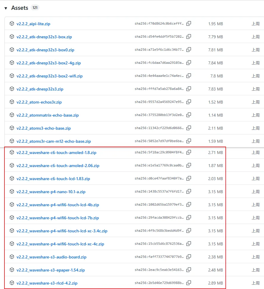
1.1 Download Firmware from XiaoZhi Official GitHub
Visit the XiaoZhi GitHub to download the firmware file for your device. Click Assets to expand the full file list:
Refer to the Flash Firmware Flashing and Erasing Tutorial to complete the firmware flashing.
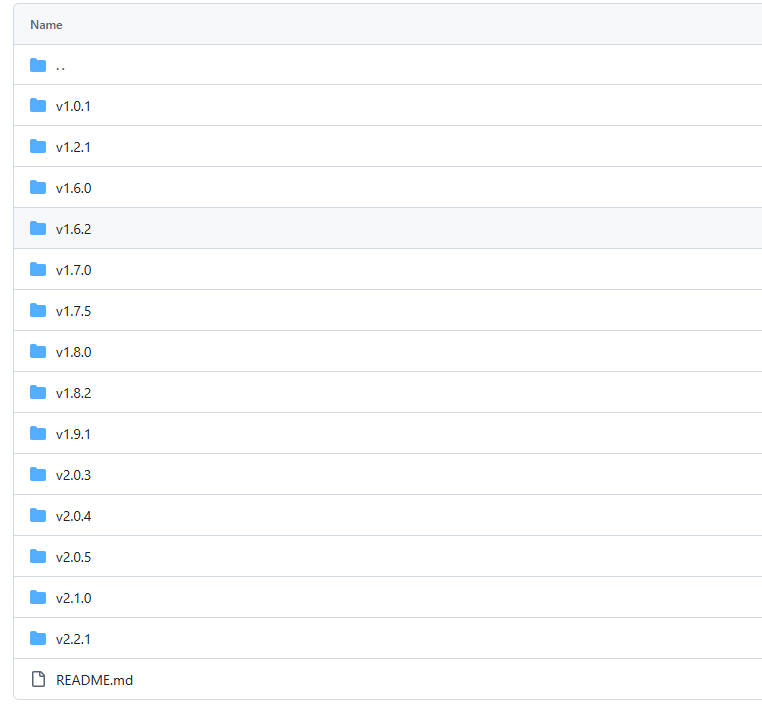
1.2 Download Firmware from Waveshare GitHub
This repository aggregates firmware for Waveshare ESP32 development boards that support XiaoZhi AI. All firmware has been tested and verified on the corresponding boards, making it convenient for users to find and download. Firmware versions may be updated slightly later than the official XiaoZhi repository.
Visit the Waveshare GitHub repository and download the appropriate firmware version for your needs:
Refer to the Flash Firmware Flashing and Erasing Tutorial to complete the firmware flashing.
2. Flashing with ESP-IDF Environment
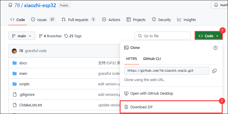
2.1 Download the Project from XiaoZhi GitHub
Visit the XiaoZhi AI Chatbot repository to download the complete project code:
2.2 Environment Setup
Refer to the ESP-IDF Environment Setup Tutorial to configure the development environment.
2.3 Configuration and Compilation
Click
 to select the target device. Choose the chip model corresponding to your development board (e.g.,
 esp32s3):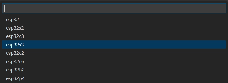 TIP
TIPWhen setting the target device, ESP-IDF will automatically configure the corresponding toolchain and libraries. This process may take some time, please be patient. For more details, please refer to the Official Documentation.
Click
 to open the ESP-IDF terminal, then execute the command
 idf.py menuconfigto enter the configuration interface. Select Xiaozhi Assistant: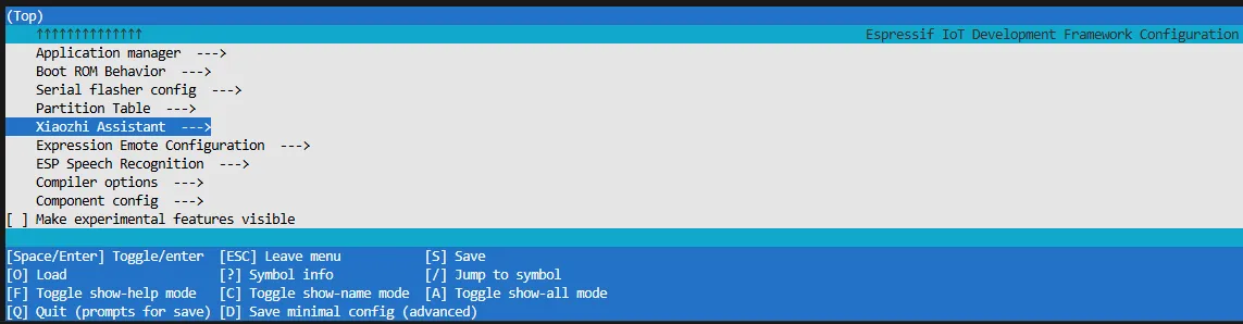
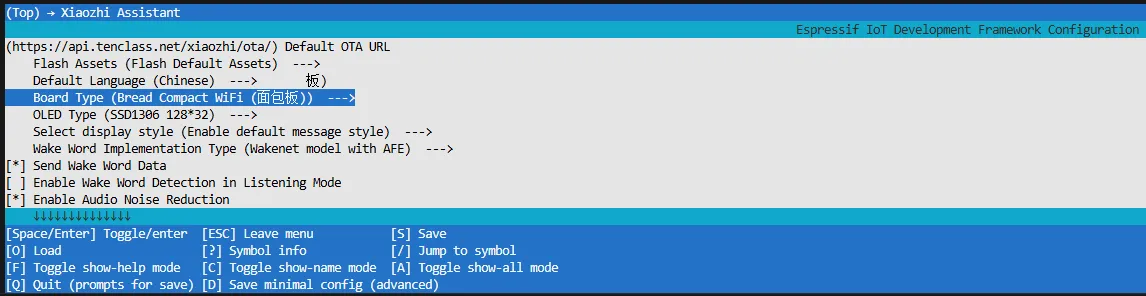
Select Board Type to choose the development board type:
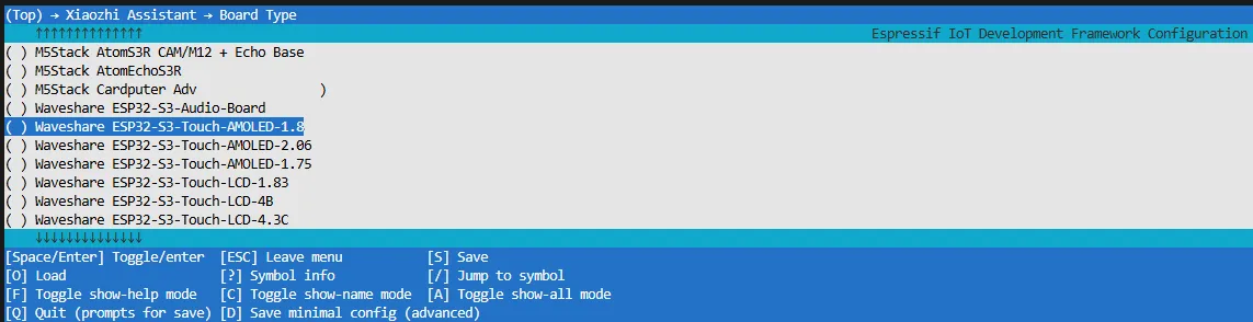
Choose the product model corresponding to your development board:
Press the S key to save the configuration and exit. Then click the
 to automatically complete compilation, flashing, and serial monitoring.
2.4 Start Network Provisioning
Connect your phone or computer to the device's Wi-Fi hotspot: Xiaozhi-xxxxxx. After successful connection, the configuration page should automatically pop up. If not, manually open a browser and visit
http://192.168.4.1.On the network configuration page, select the Wi-Fi name you want to connect to (only 2.4G band is supported; to connect to an iPhone hotspot, enable Max Compatibility in your phone's system settings). The SSID will be auto-filled. Enter the password and click Connect to start connecting:

2.5 Add a New Device to the Management Console
Ensure the device has successfully connected to the Internet. The device will then broadcast a 6-digit device verification code (you can wake the device again to replay the code).
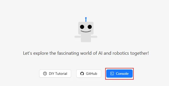
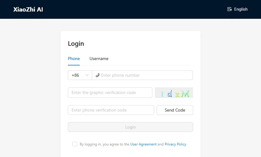
Visit the XiaoZhi AI Console. If you haven't registered, complete the registration and log in:
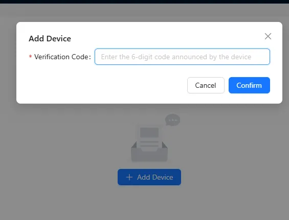
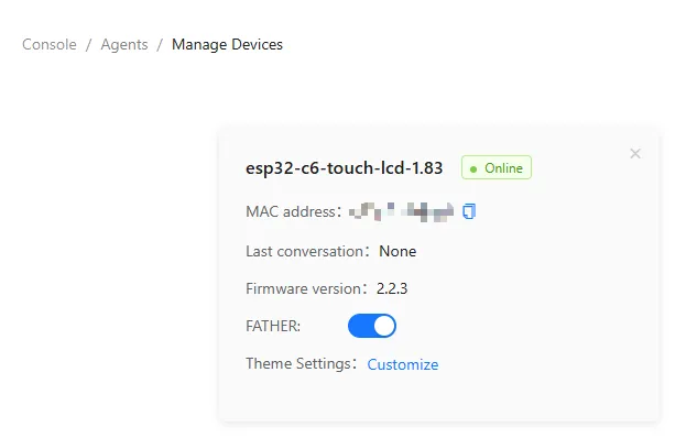
Enter the 6-digit verification code. The device will automatically activate and appear on the Device Management page, ready for normal use.
Say the wake word "Hello XiaoZhi" to wake the device and start voice conversations.
ESP32-S3-Touch-AMOLED-1.8 Button Instructions:
- BOOT button: Press to wake XiaoZhi
- PWR button: Short press to power on; long press for more than 6 seconds to power off
3. XiaoZhi Resources
Resources
1. Hardware Resources
Development Board Design Files
2. Technical Manuals
Official ESP32-S3 Chip Manuals
Datasheets
3. Demo
[Tutorial Navigation]
- Features
- Onboard Resources
- Dimensions
- Working with Arduino
- Arduino Getting Started
- Setting Up Development Environment
- Demo
- ESP-IDF
- ESP-IDF Getting Started
- Setting Up Development Environment
- Demo
- XiaoZhi AI Application Tutorial
- 0. Firmware Flashing Process Reference
- 1. Flashing Without a Development Environment
- 2. Flashing with ESP-IDF Environment
- 2.1 Download the Project from XiaoZhi GitHub
- 2.2 Environment Setup
- 2.3 Configuration and Compilation
- 2.4 Start Network Provisioning
- 2.5 Add a New Device to the Management Console
- 3. XiaoZhi Resources
- Resources