- sales/support
Google Chat:---
- sales
+86-0755-88291180
- sales01
sales@spotpear.com
- sales02
dragon_manager@163.com
- support
tech-support@spotpear.com
- CEO-Complaints
zhoujie@spotpear.com
- Only Tech-Support
WhatsApp:13246739196
- Purchase/Shipping/Refund
WhatsApp:13424403025
- HOME
- >
- ARTICLES
- >
- For Arduino
- >
- Mother Board
R7FA4-PLUS-B User Guide
Overview
Introduction
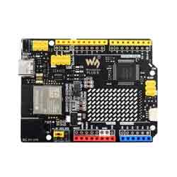
R7FA4 PlUS B combines the processing power and the new peripherals of Renesas Electronics' RA4M1 microcontroller with wireless connectivity capabilities of Espressif's ESP32-S3. In addition, the board also offers onboard 12x8 LED matrix, Qwiic connectors, VRTC and OFF pins, catering to all potential needs for your next project.
With R7FA4 PlUS B, you can easily upgrade your project and add wireless connectivity to extend the coverage of your current setup. If this is your first project, the board has everything you need to spark your creativity.
Features
- Based on R7FA4M1AB3CFM, and is compatible with Arduino UNO R4 WiFi.
- Utilizes Renesas Electronics' RA4M1 (Arm® Cortex®-M4) microcontroller, with a main frequency of 48MHz.
- Onboard ESP32-S3 module, integrates 2.4GHz Wi-Fi and Bluetooth LE dual-mode wireless communication, allowing the maker to use it for wireless communication. Combined with Arduino IoT Cloud, you can remotely monitor and control the projects.
- Onboard 12x8 red LED matrix, suitable for creative projects with animation or plotting sensor data, no additional hardware is required.
- Equipped with 256 kB Flash and 32 kB RAM, the expanded memory can easily handle complex projects.
- The R7FA4 Plus development board adds a 12-bit DAC, CAN bus and operational amplifiers, providing expanded functionality and flexibility for designs.
- Onboard 5V/3.3V headers for easy voltage switching, allowing the use of more expansion modules.
- Flexible power options, supporting USB-C power supply or external input power VIN (6V<=VIN<=21V).
- Onboard power indicator (PWR), USER LED, serial port receive indicator (RX), and transmit indicator (TX), making it easy to monitor the working status of the development board.
- Onboard ICSP interface, can be used as an SPI interface.
- Supports user soldering of corresponding interface insertion into the experimental board.
Product Parameters Comparison
| MODEL |
|
|
|
|---|---|---|---|
| MICROCONTROLLER | R7FA4 (32-bit ARM Cortex-M4) | R7FA4 (32-bit ARM Cortex-M4) | ESP32-S3R8 (Dual-core 32-bit Xtensa LX7) |
| ESP32-S3FN8 (Dual-core 32-bit Xtensa LX7) | |||
| CLOCK FREQUENCY | R7FA4: 48MHz | R7FA4: 48MHz | ESP32-S3R8: 240MHz |
| ESP32-S3FN8: 240MHz | |||
| STORAGE | R7FA4: 256kB Flash, 32kB RAM | R7FA4: 256kB FLASH, 32kB RAM | ESP32-S3R8: 384kB ROM, 512kB RAM, 16MB Flash, 8MB PSRAM |
| ESP32-S3FN8: 384kB ROM, 512kB RAM, 8MB Flash | |||
| WIRELESS COMMUNICATION | None | 2.4GHz WiFi + Bluetooth LE | |
| OPERATING VOLTAGE | Options for 5V/3.3V, support more shields | 3.3V | |
| POWER INPUT | 6~24V | 6~21V | |
| RESET BUTTON | Lateral, easier to use when connecting with shield | Vertical | |
| IO PIN OUTPUT CURRENT | 8mA | 40mA | |
| DIGITAL PINS | 14 | 14 | |
| ANALOG PINS | 6 | 8 | |
| DAC | 2 | None | |
| PWM | 6 | 5 | |
| UART | 1 | 2 | |
| I2C | 1 | 1 | |
| SPI | 1 | 1 | |
| CAN | 1 | None | |
| DC JACK | Low profile, shields won't be blocked anymore while connecting | None | |
| POWER OUTPUT HEADER | Provides 5V OR 3.3V power output and common-grounding with other boards | None | |
| 5V POWER OUTPUT | Up to 2000mA Max, features higher driving capability | 1000mA Max | |
| EXPERIMENTAL BOARD | Support, the solder pad is provided for DIY interfaces to connect with the experimental board | Support | |
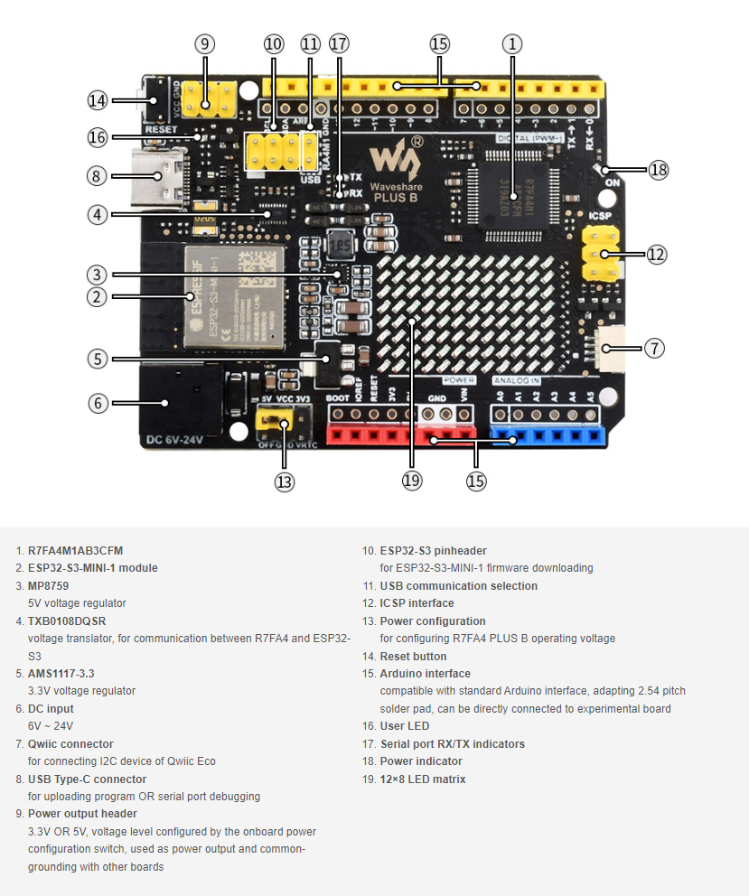
Hardware Description
Onboard Interface
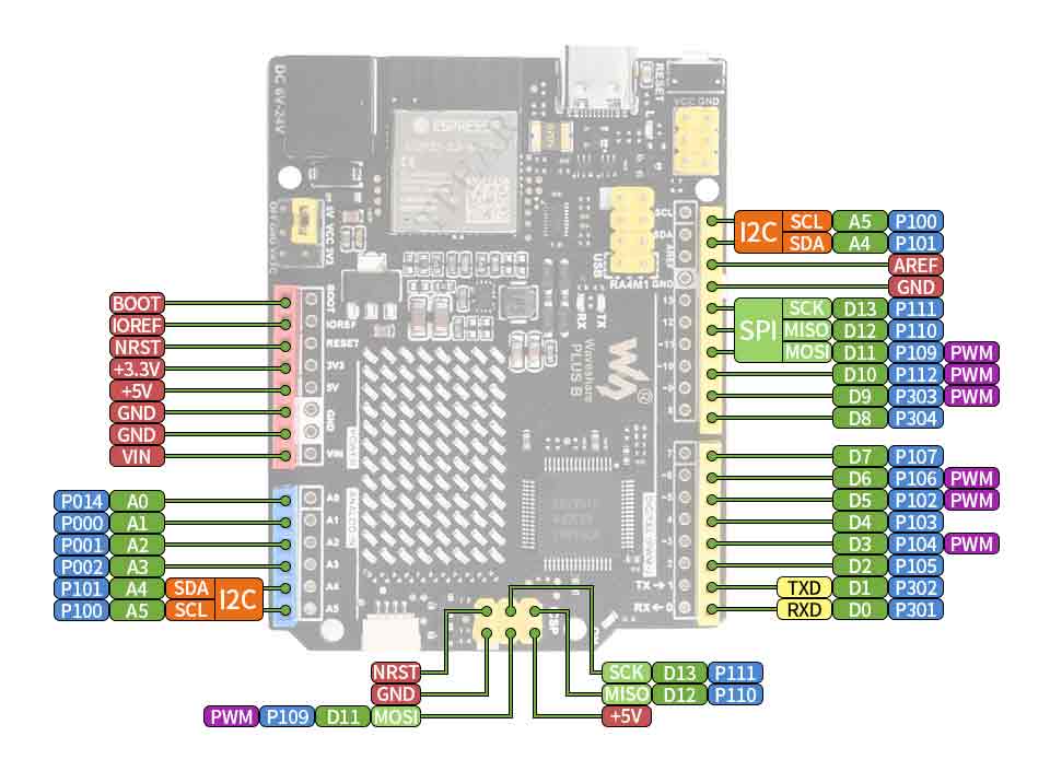
Pinout Definition
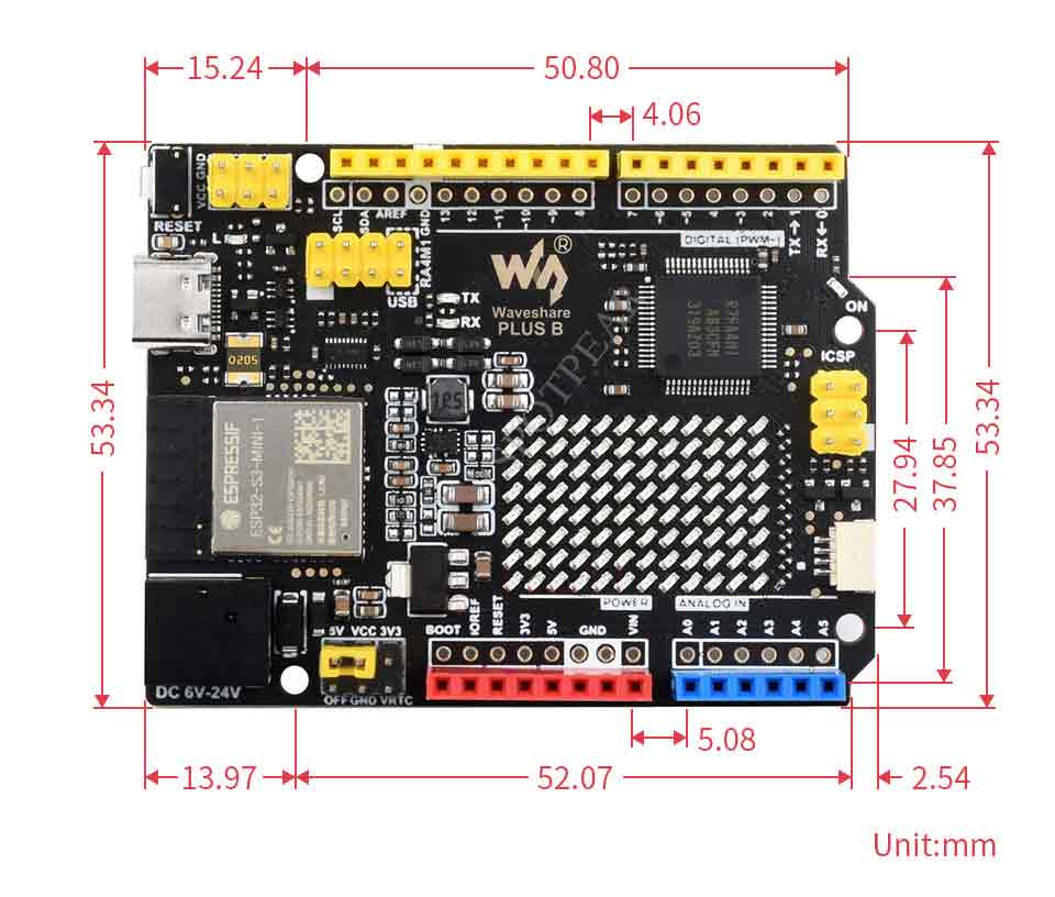
Dimensions
Arduino IDE Development
Install Arduino IDE
- The following development is based on Windows by default.
- Open download page, and select the corresponding one to download according to your system and system bits.
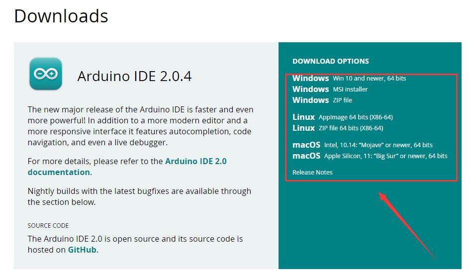
- Select "JUST DOWNLOAD" OR "CONTRIBUTE DOWNLOAD".

- Just run to install and install all the defaults.
Install Board Package
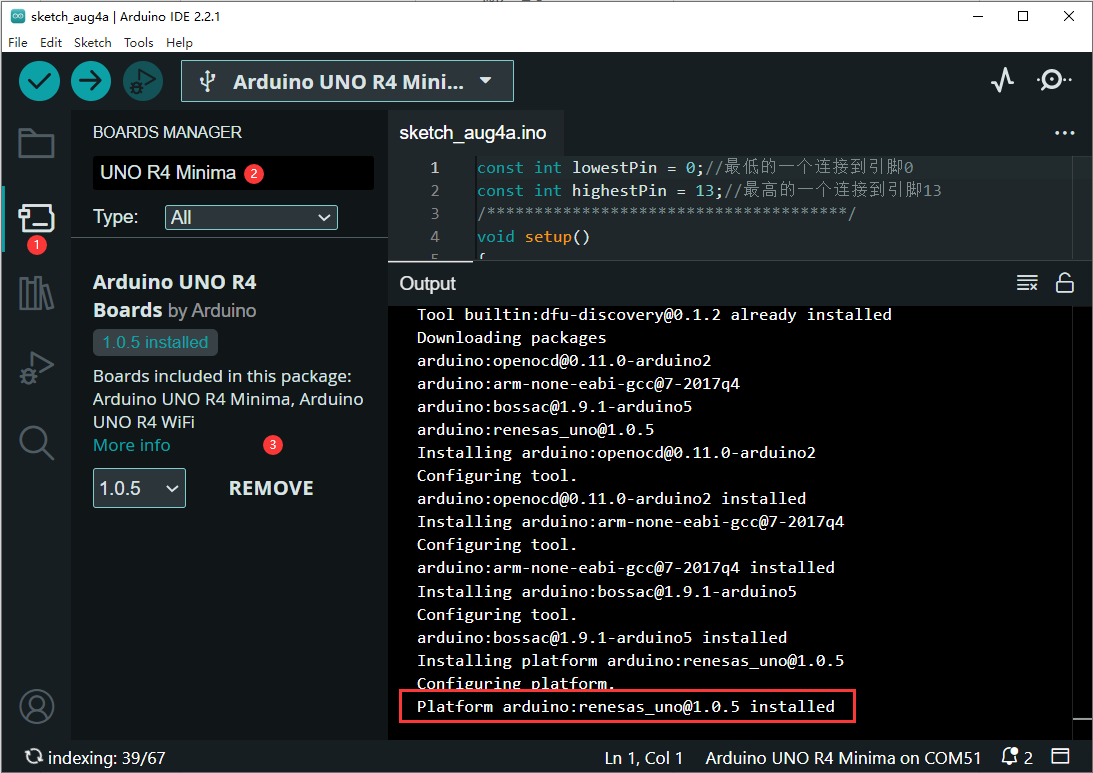
- Please open "Board Manager" on the left, search "UNO R4 Minima" and install the latest version (or the version to be used):
Create Example
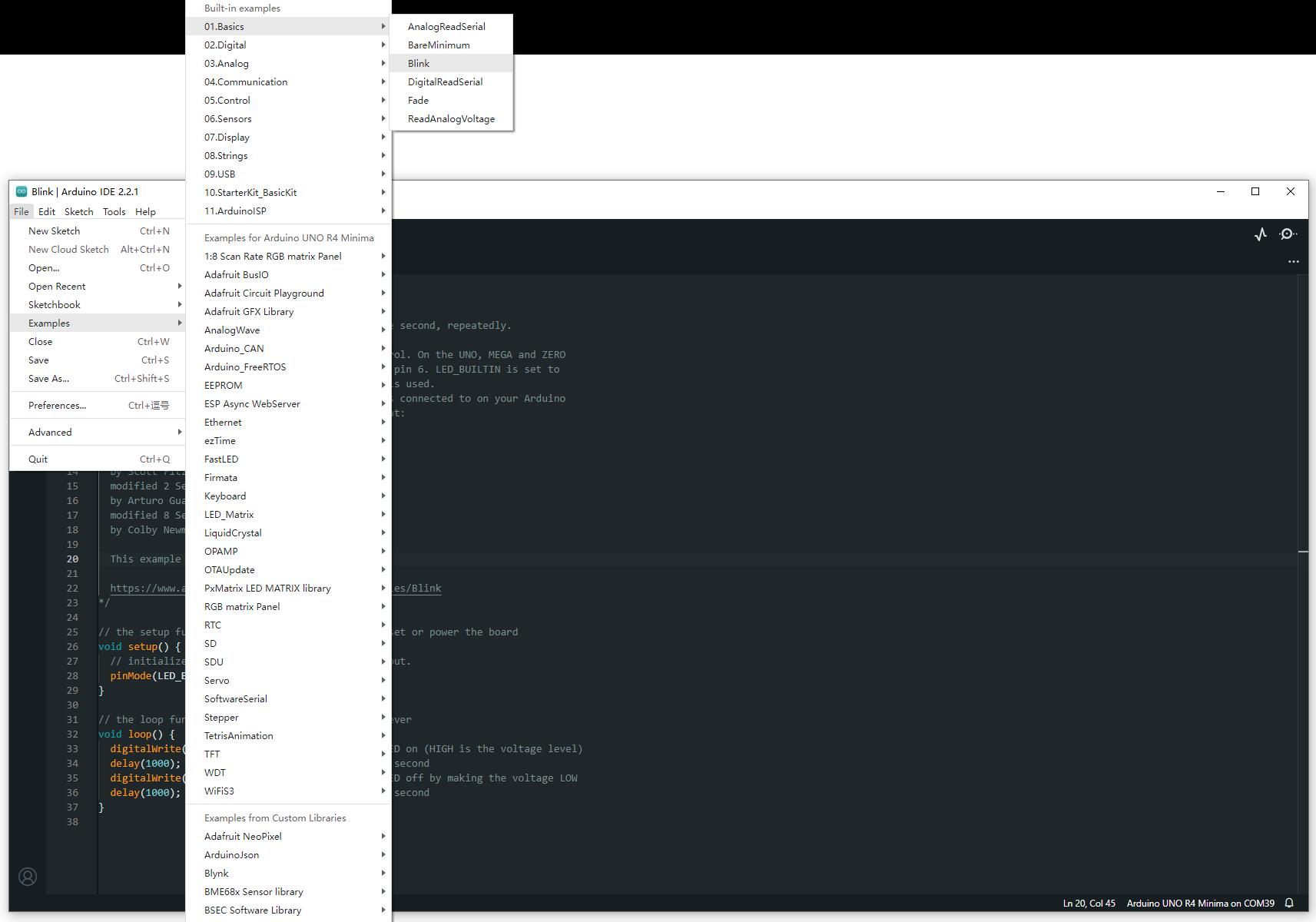
- The following example is about how to make LED blinks (File -> examples -> Blink under 01.Basics).
- Select the development board and COM port.
Search UNO R4, select Arduino UNO R4 WiFi, and then click on "OK".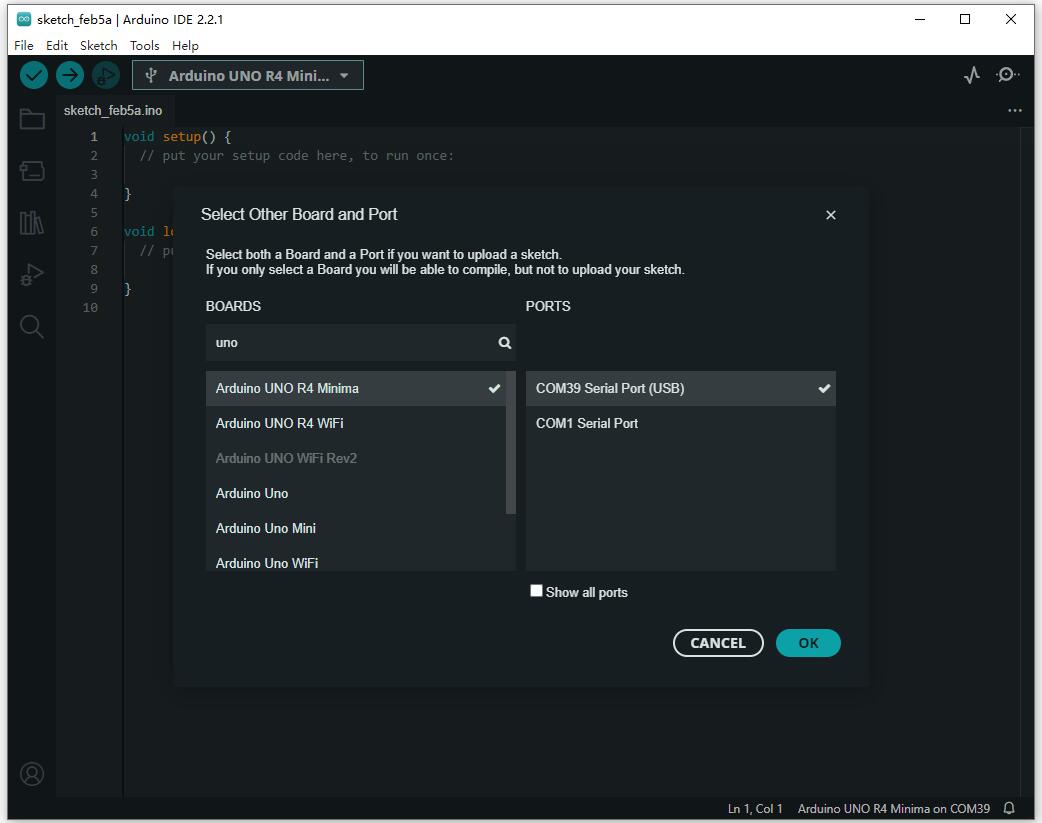
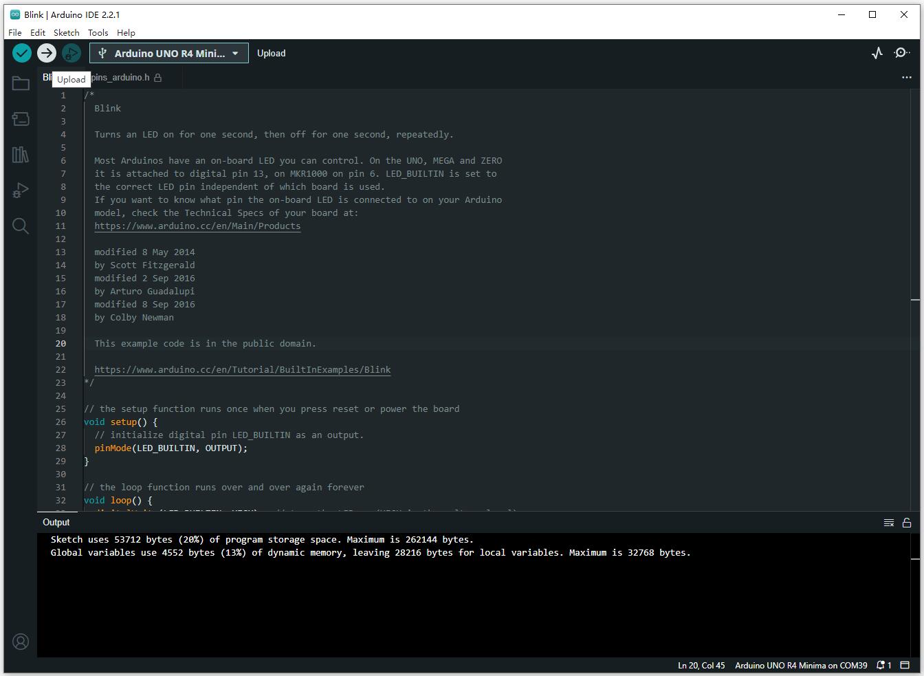
- Click ✓ in the menu bar to compile, and click → to burn the compiled program to the board.
Open Example
- Open the existing example, the operation is simpler, directly run the corresponding .ino demo, refer to the operation above, select the corresponding board and port, compile, download and burn.
Example Explanation
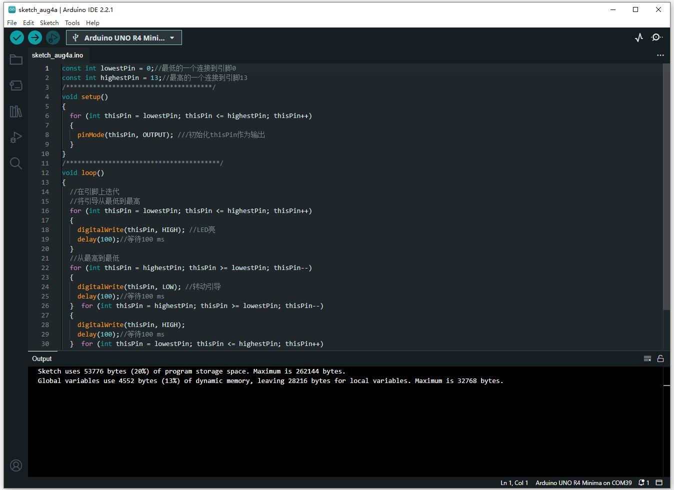
GPIO_TEST
This demo is for testing the GPIO0-13 output, in this demo, the GPIO0-13 is initialized as output mode and outputs the high level or low level in order.
ADC_TEST
The Photosensitive demo obtains the value of the photosensitive resistor by reading the value of the pins A0-A5. If the value is greater than or equal to 730, the LED will be on and the relay pin will be switched on. Otherwise, the LED pin will be off and the relay pin will be switched off.
The Read_Analog_Input demo obtains the value of the analog pin of the raindrop sensor by reading the value of pin A0. If the value is less than 500, the LED is on; otherwise, the LED is off.
MatrixIntro
The MatrixIntro demo is a 12 × 8 LED matrice that can be illuminated and programmed to modify the display screen.
test_WIFI
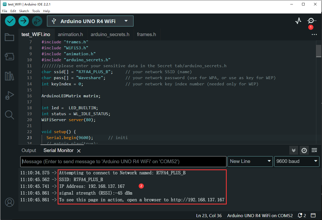
This demo is for R7FA4 PLUS B in STA (Station) mode, connected to the same Wi-Fi network as a PC. (Ensure that the R7FA4 PLUS B connects to a Wi-Fi network operating on the 2.4GHz frequency band. If the network doesn't support the 2.4GHz band, you can use the PC as a hotspot with the network frequency set to "Any available frequency.") Remember to update the ssid and the password with the Wi-Fi network name and password you want to connect to. Additionally, you can modify the 12x8 LED matrix display through programming.
- Use the PC to open the hotspot, burn the code and wait for the R7FA4 PLUS B to connect to the PC's hotspot (in the picture, ssid is the name of the hotspot that the R7FA4 PLUS B is going to connect to, and pass is the password of the hotspot that the R7FA4 PLUS B is going to connect to). Open the serial monitor to check whether the R7FA4 PLUS B is connected successfully, and you can see that there is an IP address assigned if successful.
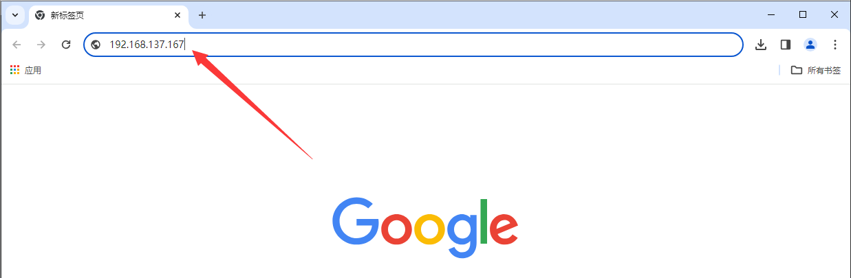
- Copy the IP address and open the webpage.
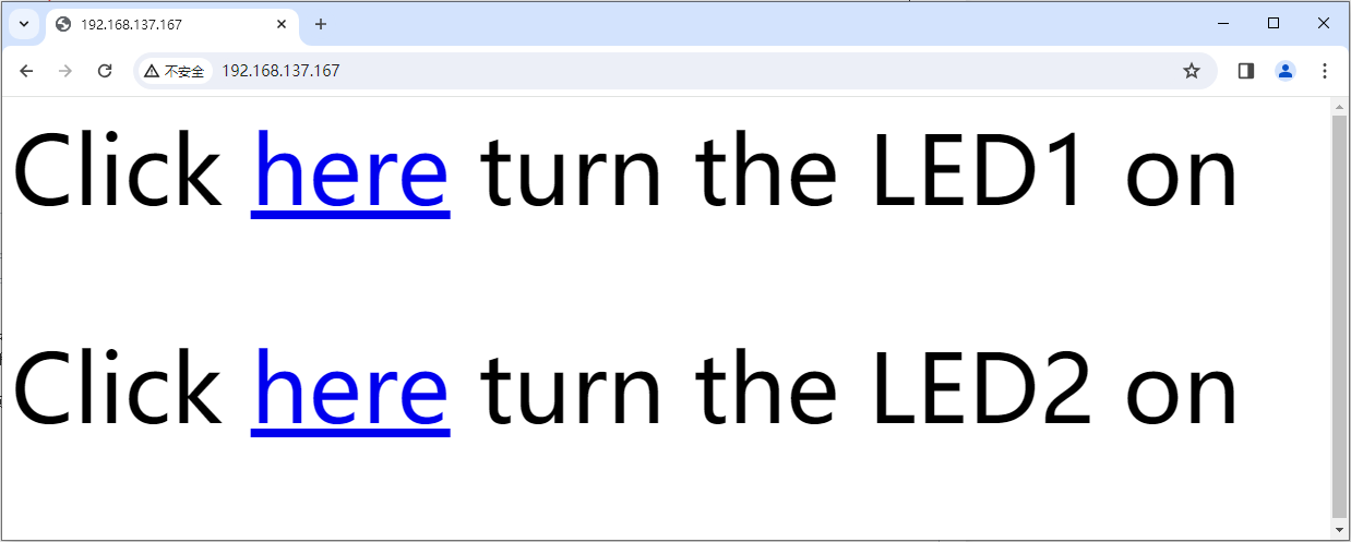
- Enter the webpage, and click on "here" to observe the 12 × 8 LED matrix display changes.
Resource
Document
Software
Related Tutorial
Related Tutorials
Support
Monday-Friday (9:30-6:30) Saturday (9:30-5:30)
Email: services01@spotpear.com