- sales/support
Google Chat:---
- sales
+86-0755-88291180
- sales01
sales@spotpear.com
- sales02
dragon_manager@163.com
- support
tech-support@spotpear.com
- CEO-Complaints
zhoujie@spotpear.com
- Only Tech-Support
WhatsApp:13246739196
- Purchase/Shipping/Refund
WhatsApp:13424403025
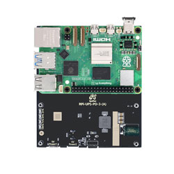
RPi-UPS-PD-3-(A) User Guide
【I2C enable and Search】
】Enable I2C
[] Method 1
Enable i2c in config.txt sudo nano /boot/config.txt
Add at the bottom of the configuration file
dtparam=i2c_arm=on
Crtl+O to save, Ctrl+X to exit
sudo reboot
Reboot to take effect
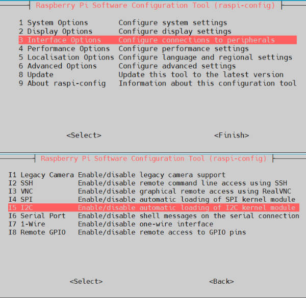
[] Method 2
Use the raspi-config command to select and enable i2c
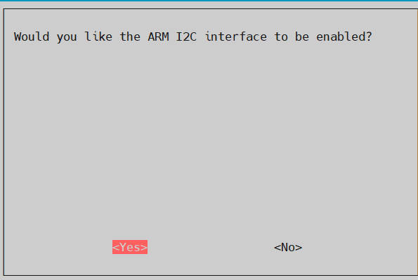
sudo raspi-config --> Interface Options --> I2C --> YES --> OK
[] Method 3
Use raspi-config to directly enable i2c
sudo raspi-config nonint do_i2c <0/1>
Parameter 0: Enable I2C
Parameter 1: Disable I2C
】Search enabled i2c devices

】Search i2c device address
Because i2c1 is enabled by default and UPS also uses i2c1, here we only use i2c1 as an example:
sudo i2cdetect -y 1
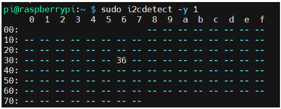
The address of the power reading and writing chip is detected to be 0x36
【GUI display battery status】
】Install Software
sudo apt-get update
sudo apt-get install python3-tk
】Edit code file
sudo mkdir -m a+x ./battery_status_code
cd ./battery_status_code
sudo nano ./battery_status_GUI_app.py
】Add the following code to the file
import tkinter as tk
from tkinter import PhotoImage
import smbus
import time
import threading
device_address = 0x36
VCELL = 0x02
SOC = 0x04
SOC1 = 0x05
MODE = 0x06
VERSION = 0x08
CONFIG = 0x0C
COMMAND = 0xFE
bus = smbus.SMBus(1)
def read_custom_bits(device_address, register, num_bits):
num_bytes = (num_bits + 7) // 8 # 计算所需的字节数
# 从设备中读取指定字节数的数据
data = bus.read_i2c_block_data(device_address, register, num_bytes)
# 将字节数据转换为位串
bit_string = ''.join(format(byte, '08b') for byte in data)
# 从位串中提取指定位数的数据
result = int(bit_string[:num_bits], 2)
return result
def update_data():
while True:
VCELL_data = read_custom_bits(device_address, VCELL, 12)
SOC_data = bus.read_byte_data(device_address, SOC)
SOC1_data = bus.read_byte_data(device_address, SOC1)
# MODE_data = bus.read_byte_data(device_address, MODE)
# VERSION_data = bus.read_byte_data(device_address, VERSION)
# CONFIG_data = bus.read_byte_data(device_address, CONFIG)
# COMMAND_data = bus.read_byte_data(device_address, COMMAND)
# 更新标签文本
vcell_label.config(text=f"Battery voltage: {VCELL_data * 0.00125:.4f} V")
soc_label.config( text=f"Battery level: {SOC_data + (SOC1_data / 256):.2f} %")
# vcell_label.config(text=f"VCELL: {VCELL_data * 0.00125:.4f} V")
# soc_label.config(text=f"SOC: {SOC_data + (SOC1_data / 256):.2f} %")
# mode_label.config(text=f"MODE: {MODE_data}")
# version_label.config(text=f"VERSION: {VERSION_data}")
# config_label.config(text=f"CONFIG: {CONFIG_data}")
# command_label.config(text=f"COMMAND: {COMMAND_data}")
time.sleep(0.5)
def start_update_thread():
threading.Thread(target=update_data, daemon=True).start()
root = tk.Tk()
root.title("I2C Data Monitor")
root.attributes("-fullscreen", True)
# 添加Logo
logo = PhotoImage(file="/home/pi/battery_status_code/logo.png")
logo_label = tk.Label(root, image=logo)
logo_label.pack(pady=10)
vcell_label = tk.Label(root, text="Battery voltage: ", font=("Helvetica", 16))
vcell_label.pack(pady=10)
soc_label = tk.Label(root, text="Battery level: ", font=("Helvetica", 16))
soc_label.pack(pady=10)
#vcell_label = tk.Label(root, text="VCELL: ", font=("Helvetica", 16))
#vcell_label.pack(pady=10)
#soc_label = tk.Label(root, text="SOC: ", font=("Helvetica", 16))
#soc_label.pack(pady=10)
#mode_label = tk.Label(root, text="MODE: ", font=("Helvetica", 16))
#mode_label.pack(pady=10)
#version_label = tk.Label(root, text="VERSION: ", font=("Helvetica", 16))
#version_label.pack(pady=10)
#config_label = tk.Label(root, text="CONFIG: ", font=("Helvetica", 16))
#config_label.pack(pady=10)
#command_label = tk.Label(root, text="COMMAND: ", font=("Helvetica", 16))
#command_label.pack(pady=10)
button = tk.Button(root, text="Close", command=root.quit, font=("Helvetica", 16))
button.pack(pady=20)
# 启动更新数据的线程
start_update_thread()
# 绑定按键事件,按F11键切换全屏模式,按Esc键退出全屏模式
root.bind("<F11>", lambda event: root.attributes("-fullscreen", not root.attributes("-fullscreen")))
root.bind("<Escape>", lambda event: root.attributes("-fullscreen", False))
root.mainloop()
】Execute program
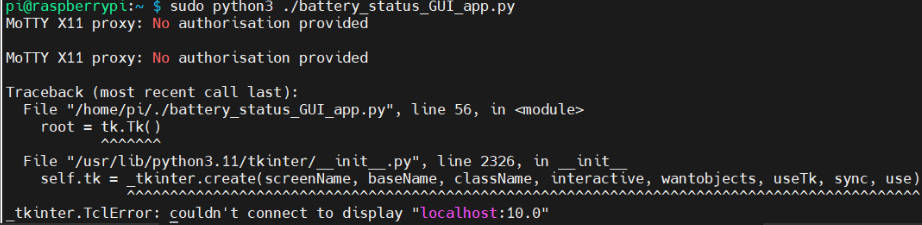
sudo python3 ./battery_status_GUI_app.py
NOTE:To execute the program in the GUI environment, if you only execute it in ssh, you will get an error "Unable to access the graphical environment"
】Automatic startup
[] Create Python script
[] Create a systemd service file
[] Add the following code to the file
[Unit]
Description=Tkinter GUI Application
After=graphical.target
[Service]
User=pi
Environment=DISPLAY=:0
ExecStart=/usr/bin/python3 /home/pi/battery_status_code/battery_status_GUI_app.py
Restart=always
[Install]
WantedBy=graphical.target
[] Reload systemd configuration
[] Enable and start the service
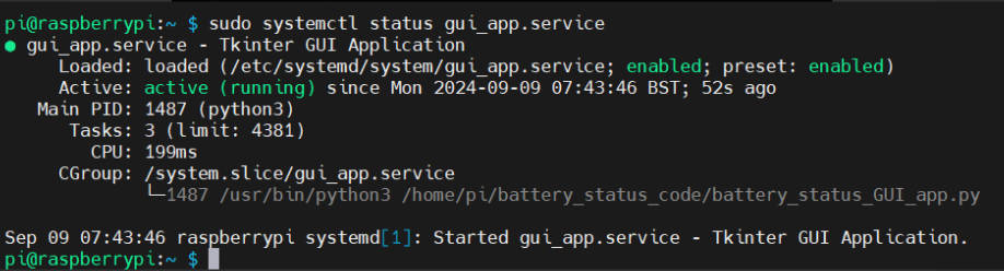
[] Verify whether the service is running
【Command line display battery status】
】Edit code file
sudo mkdir -m a+x ./battery_status_code
cd ./battery_status_code
sudo nano ./battery_status_command_app.py
】Add the following code to the file
import smbus
import time
import sys
device_address = 0x36
VCELL = 0x02
SOC = 0x04
SOC1 = 0x05
MODE = 0x06
VERSION = 0x08
CONFIG = 0x0C
COMMAND = 0xFE
bus = smbus.SMBus(1)
def read_custom_bits(device_address, register, num_bits):
num_bytes = (num_bits + 7) // 8 # 计算所需的字节数
# 从设备中读取指定字节数的数据
data = bus.read_i2c_block_data(device_address, register, num_bytes)
# 将字节数据转换为位串
bit_string = ''.join(format(byte, '08b') for byte in data)
# 从位串中提取指定位数的数据
result = int(bit_string[:num_bits], 2)
return result
def clear_screen():
# 清除屏幕并将光标移动到起始位置
sys.stdout.write("\033[H\033[J")
sys.stdout.flush()
while True:
clear_screen()
VCELL_data = read_custom_bits(device_address, VCELL, 12)
SOC_data = bus.read_byte_data(device_address, SOC)
SOC1_data = bus.read_byte_data(device_address, SOC1)
MODE_data = bus.read_byte_data(device_address, MODE)
VERSION_data = bus.read_byte_data(device_address, VERSION)
CONFIG_data = bus.read_byte_data(device_address, CONFIG)
COMMAND_data = bus.read_byte_data(device_address, COMMAND)
# 打印读取的数据
print(" Battery status \n")
print("Battery voltage:", (VCELL_data * 0.00125))
print("Battery level :", SOC_data + (SOC1_data / 256), "%")
print()
time.sleep(1)
】Execute program
sudo python3 ./battery_status_command_app.py
【Resources】
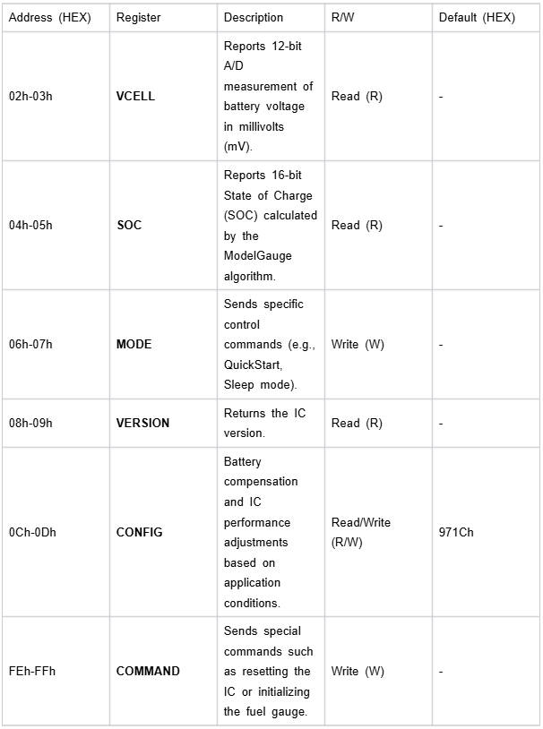
Register function explanation:
【Support】
Monday-Friday (9:30-6:30) Saturday (9:30-5:30) - (China time)
Email: services01@spotpear.com