


- sales/support
Google Chat:---
- sales
+86-0755-88291180
- sales01
sales@spotpear.com
- sales02
dragon_manager@163.com
- support
tech-support@spotpear.com
- CEO-Complaints
zhoujie@spotpear.com
- Only Tech-Support
WhatsApp:13246739196
- Purchase/Shipping/Refund
WhatsApp:13424403025
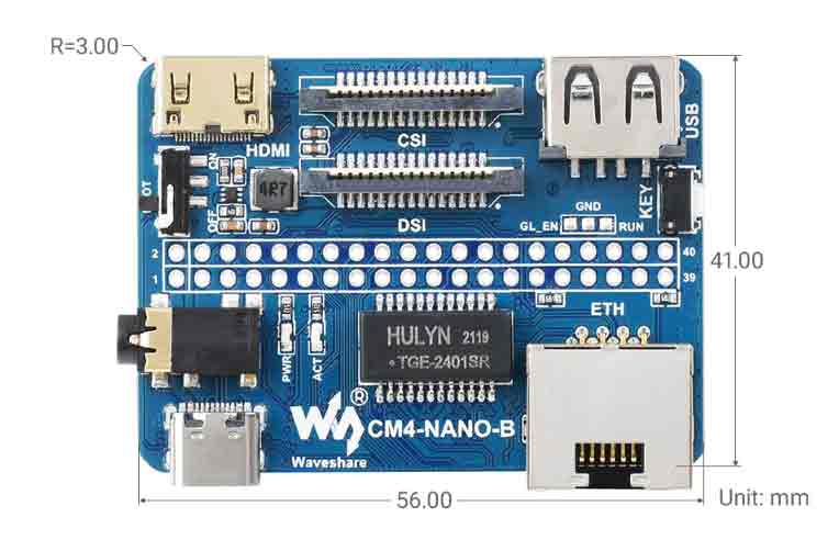
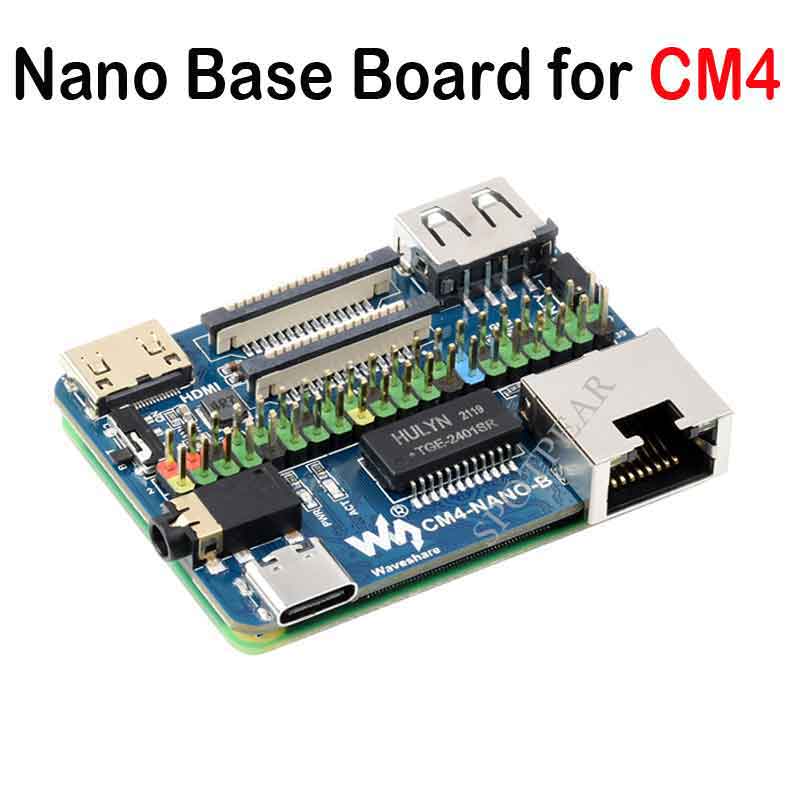
Raspberry Pi CM4-NANO-B User Guide
Overview
Product description
CM4-NANO-B (Raspberry Pi CM4 Ultra Mini Expansion Board Type B) is a baseboard that can be used with Raspberry Pi Compute Module 4. Although it is tiny, it can bring out the interface of Raspberry Pi Compute Module 4.
Precautions for use
1. DO NOT hot-plug any devices except the USB and HDMI.
2. As the module does not have any protection, please do not short-circuit the power supply.
3. The USB Type-C interface can be used as a power supply or as a USB SLAVE interface to program the image.
4. In order to ensure the normal power supply of the CM4, please do not connect other devices when using the USB Type-C interface to program the image.
5. Providing 5V 2A for CM4 to ensure that it is in normal use. Otherwise, there may be problems such as automatic shutdown, frequency reduction and so on.
6. The USB2.0, CSI, DSI and Audio interfaces are disabled by default and need to be enabled by the user.
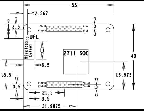
Dimension
CM4-NANO-B
Compute_Module 4
Onboard Resources
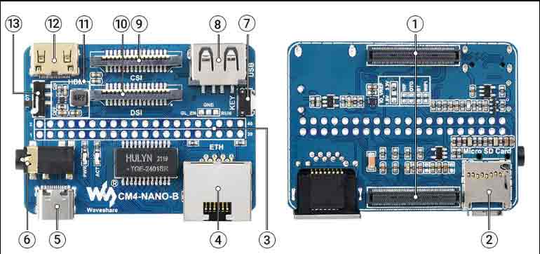
| Label | Name | Description |
| 1 | CM4 socket | suitable for all variants of Compute Module 4 |
| 2 | Micro SD card interface | For inserting a Micro SD card with the system, only for Lite version |
| 3 | 40PIN GPIO interface | Easy access to various HAT modules |
| 4 | Ethernet port | RJ45 Gigabit Ethernet port, support 10 / 100 / 1000M network access |
| 5 | Power supply/burning interface | 5V/2A power supply, can also be used as eMMC programming interface |
| 6 | Audio Interface | 3.5mm audio interface |
| 7 | User button | Support various USB device |
| 8 | USB2.0 | Indicates the working status of the Raspberry Pi |
| 9 | CAM interface | MIPI CSI camera interface, connect with CM4 CSI0 interface |
| 10 | DSI | MIPI DSI display interface, connect with CM4 DSI1 interface |
| 11 | DC step-down circuit | DC buck circuit to power 3.3V for DSI, CSI and GPIO |
| 12 | MINI HDMI | HDMI interface, support 4K 30fps output |
| 13 | BOOT | ON: Switch the USB to type C interface, and enter the download mode when powered on (configured as a large-capacity disk through rpi boot) OFF: Switch the USB to TYPE A interface, it will not enter the download when powered on (start from eMMC or SD card) |
Usage Introduction
Writing Image
- According to the version of CM4 you are using, the image programming can be divided into two versions: EMMC and LITE. Please choose the version below according to your CM4 to watch.
- Write Image for Compute Module Boards eMMC version
- Write Image for Compute Module Boards Lite version
USB2.0
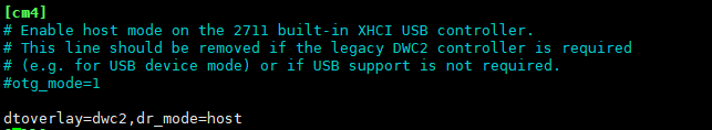
USB enable configuration
- The USB port is disabled by default on the CM4 to save power.
- It is recommended to directly open the config.txt file in the boot drive letter after the programming is completed, and add the following content:
dtoverlay=dwc2,dr_mode=host
- After saving the file, start the machine according to the normal process
USB-OTG Mode
- If you use the latest Raspberry Pi OS (image after October 30, 2021) and USB2.0 is in OTG mode by default, CM4 will report an error.
config failed, hub doesn't have any ports! (err -19)
- However, USB can still be used. If you want to remove this error, remove otg_mode=1 in [cm4] of config.txt, and add dtoverlay=dwc2, dr_mode=host (USB cannot be recognized without adding it).
CSI and DSI
Configuration
- Due to CSI and DSI are disabled by default, we need to load device tree to open, and three I2C devices, I2C-10, I2C-11, and I2C-0, will be occupied when using the CSI camera and DSI screen.
- Enter the following command:
sudo apt-get install p7zip-full
wget https://www.waveshare.net/w/upload/4/41/CM4_dt_blob.7z
7z x CM4_dt_blob.7z -O./CM4_dt_blob
sudo chmod 777 -R CM4_dt_blob
cd CM4_dt_blob/
#If executed with two cameras and DSI1
sudo  dtc -I dts -O dtb -o /boot/dt-blob.bin dt-blob-disp1-double_cam.dts
#When using any DSI, HDMI1 has no image output, even if you do not connect the DSI screen, as long as you compile the corresponding file, then HDMI1 will not output.
#If you need to restore, just delete the corresponding dt-blob.bin: sudo rm -rf /boot/dt-blob.bin
#After the execution is complete, turn off the power and restart the CM4
Open CSI Camera
- In addition to modifying the device tree, the CSI camera also needs to be set to enable the camera function
Old version (buster)
1. Execute the following command to enter the Raspberry Pi configuration
sudo raspi-config
2. Choose Interfacing Options and enter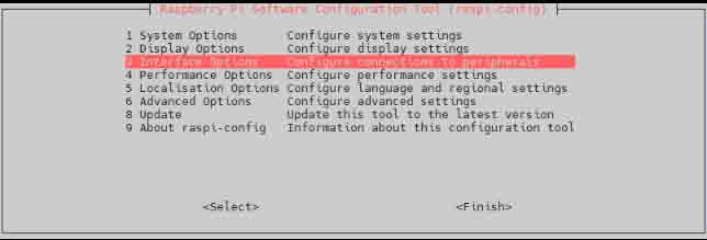
3.Choose Camera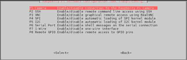
4.Choose to open camera interface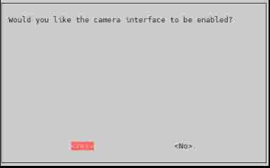
5.The system prompts as follows: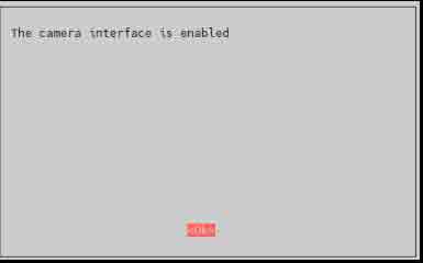
6.Back to the main interface, select Finish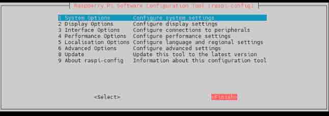
7.Reboot the system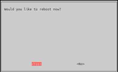
New version (bullseye)
1. Execute the following command to enter the Raspberry Pi configuration
sudo raspi-config
2. Select Interfacing Options and enter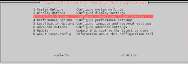
3. Choose to open camera interface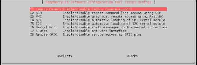
4. Choose to enable legacy camera support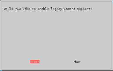
5. The system prompts as follows: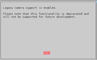
6.Back to the main interface, select Finish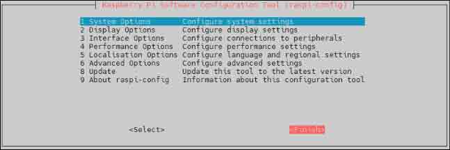
7.Then reboot the system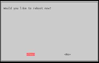
CSI Camera Test
- Make sure to connect the CSI camera and DSI screen in a power-off state, otherwise the equipment may be damaged
- Test photo:
raspistill -o image.jpg
- Test video
raspivid -o video.h264 -t 10000
- Where -t 10000 means recording for 10 seconds, users can adjust according to their own needs.
Refer to CSI camera
Audio Interface
- The Audio of this device uses GPIO audio output, GPIO18 and GPIO19, which need to be turned on through the configuration file
1. edit config.txt
sudo nano /boot/config.txt
2.add content at the bottom
dtparam=audio=on
dtoverlay=audremap,pins_18_19
3.Enter to the graphical interface, right-click the volume icon, and select AV Jack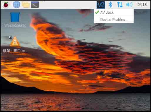
- PS: When switching to Audio interface, the audio output of HDMI will stop