


- sales/support
Google Chat:---
- sales
+86-0755-88291180
- sales01
sales@spotpear.com
- sales02
dragon_manager@163.com
- support
tech-support@spotpear.com
- CEO-Complaints
zhoujie@spotpear.com
- Only Tech-Support
WhatsApp:13246739196
- Purchase/Shipping/Refund
WhatsApp:13424403025
- HOME
- >
- ARTICLES
- >
- Common Moudle
- >
- ESP
ESP32-S3-Touch-LCD-2.1 User Guide
Overview
Introduction
ESP32-S3-Touch-LCD-2.1 is a microcontroller development board that supports 2.4GHz Wi-Fi and BT BLE 5. It integrates large capacity Flash and PSRAM and has onboard 2.1inch capacitive touch screen, can smoothly run GUI programs such as LVGL. Combined with various peripheral interfaces, it is suitable for the quick development of the HMI and other ESP32-S3 applications.
Features
- Equipped with high-performance Xtensa 32-bit LX7 dual-core processor, up to 240MHz main frequency
- Supports 2.4GHz Wi-Fi (802.11 b/g/n) and Bluetooth 5 (BLE), with onboard antenna
- Built in 512KB SRAM, 384KB ROM, 8MB PSRAM, and 16MB Flash
- Onboard 2.1inch capacitive touch screen with 480 × 480 resolution, 262K color
- Supports touch control via I2C interface, with interrupt support
- Adapting UART, I2C and some IO interfaces, integrates full-speed USB port
- Onboard QMI8658 6-axis sensor, RTC clock sensor, TF card slot and battery charging management module, etc.
- Supports accurate control such as flexible clock and multiple power modes to realize low power consumption in different scenarios
Onboard Resources
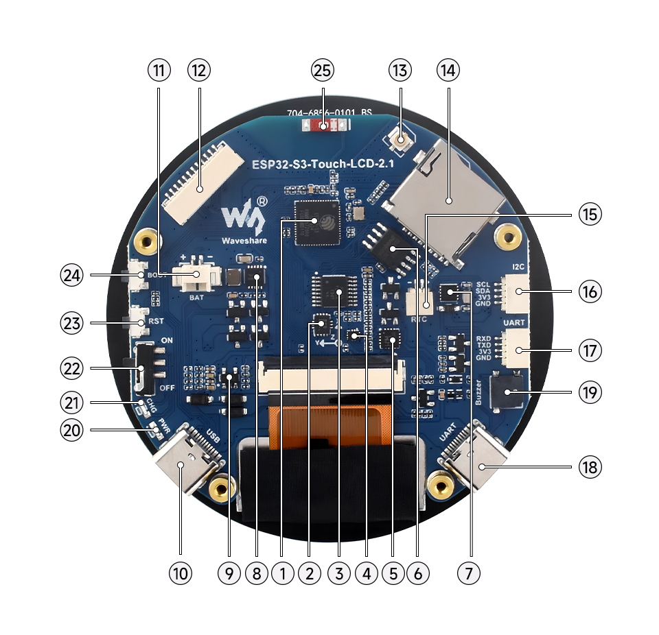
1. ESP32-S3R8 2. QST attitude sensor 3. TCA9554PWR 4. FSUSB42UMX 5. CH343P 6. 16MB Flash 7. RTC clock chip 8. Battery recharge manager Chip 9. ME6217C33M5G 10. USB Type-C port 11. Battery header | 12. 12PIN multi-functional pin header 13. IPEX Gen 1 connector 14. TF card slot 15. RTC battery header 16. I2C interface 17. UART interface 18. USB TO UART Type-C port 19. Buzzer 20. Power indicator 21. Charge indicator 22. Battery power supply control button 23. RESET button 24. BOOT button |
Interfaces
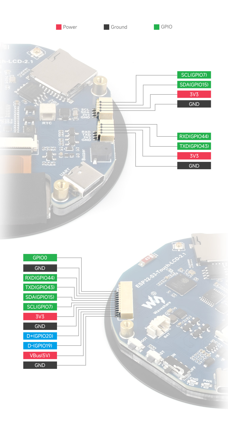
- 12PIN connector
| No. | Pin | Function | Description |
| 1 | GND | GND | Ground |
| 2 | VBus | 5V | USB power supply |
| 3 | D- | USB differential cable (GPIO19) | USB differential cable or as GPIO |
| 4 | D+ | USB differential cable (GPIO20) | USB differential cable or as GPIO |
| 5 | GND | GND | Ground |
| 6 | 3V3 | 3V3 | 3.3V external output |
| 7 | SCL | SCL (GPIO7) | I2C clock pin, cannot be used as GPIO |
| 8 | SDA | SDA (GPIO15) | I2C data pin, cannot be used as GPIO |
| 9 | TXD | TXD (GPIO43) | UART transmit data or as GPIO |
| 10 | RXD | RXD (GPIO44) | UART receive data or as GPIO |
| 11 | NC | NC | Not connected |
| 12 | IO0 | GPIO0 | Spare pinout |
- I2C interface
| Pin | Function | Description |
| GND | GND | Ground |
| 3V3 | 3V3 | 3.3V external output |
| SCL | SCL (GPIO7) | I2C clock pin, cannot be used as GPIO |
| SDA | SDA (GPIO15) | I2C data pin, cannot be used as GPIO |
- UART interface
| Pin | Function | Description |
| GND | GND | Ground |
| 3V3 | 3V3 | 3.3V external output |
| TXD | TXD (GPIO43) | UART transmit data or as GPIO |
| RXD | RXD (GPIO44) | UART receive data or as GPIO |
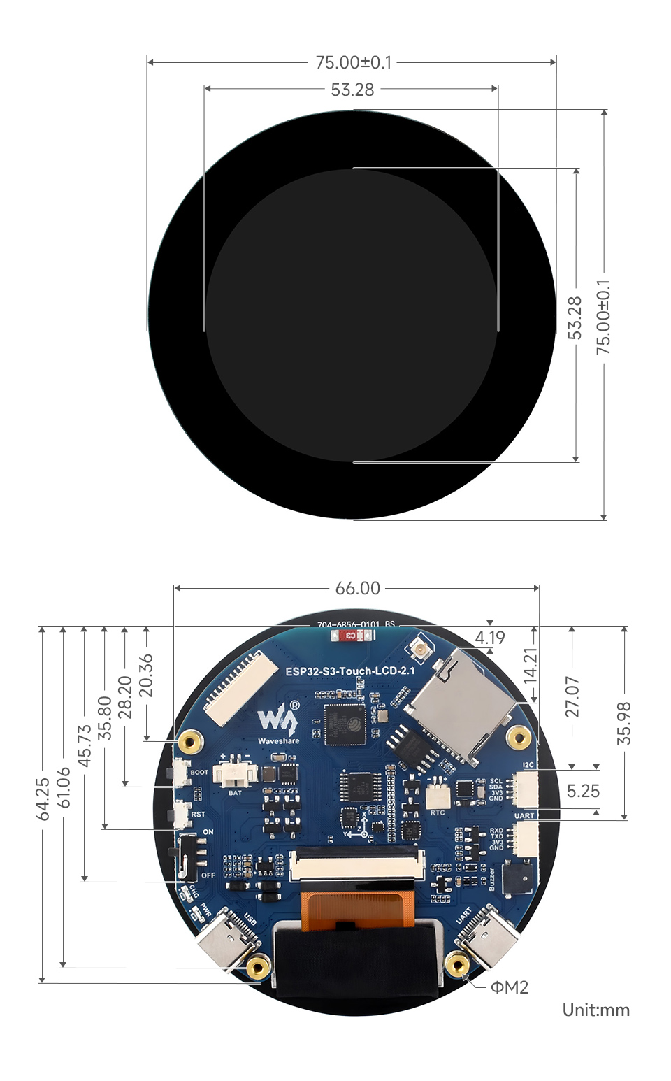
Dimensions
Specifications
| Item | Parameter |
| Interface | USB Type-C / UART Type-C |
| Controller chip | ESP32-S3 |
| LCD Type | TFT |
| LCD Controller | Display: ST7701 |
| Touch: CST820 | |
| Onboard Devices | Attitude sensor: QMI8658 |
| RTC clock: PCF85063 | |
| TF | |
| Buzzer | |
| Battery Recharging Manager Module | |
| Dimensions | 75.00±0.1 (R) mm |
Internal Hardware Connection
The product utilizes the ESP32-S3, hence it only supports RGB565 in both hardware and software. For more details, please refer to RGB LCD Introduction
LCD
| LCD Pin | ESP32S3 |
| LCD_BL | GPIO6 |
| LCD_RST | EXIO1 |
| LCD_SDA | GPIO1 |
| LCD_SCL | GPIO2 |
| LCD_CS | EXIO3 |
| PCLK | GPIO41 |
| DE | GPIO40 |
| VSYNC | GPIO39 |
| HSYNC | GPIO38 |
| B0 | NC |
| B1 | GPIO5 |
| B2 | GPIO45 |
| B3 | GPIO48 |
| B4 | GPIO47 |
| B5 | GPIO21 |
| G0 | GPIO14 |
| G1 | GPIO13 |
| G2 | GPIO12 |
| G3 | GPIO11 |
| G4 | GPIO10 |
| G5 | GPIO9 |
| R0 | NC |
| R1 | GPIO46 |
| R2 | GPIO3 |
| R3 | GPIO8 |
| R4 | GPIO18 |
| R5 | GPIO17 |
| TP_SDA | GPIO15 |
| TP_SCL | GPIO7 |
| TP_INT | GPIO16 |
| TP_RST | EXIO2 |
TF Card
| TF Card | ESP32S3 |
| SD_D0 / MISO | GPIO42 |
| SD_CMD / MOSI | GPIO1 |
| SD_SCK / SCLK | GPIO2 |
| SD_D3 / CS | EXIO4 |
| SD_D1 | NC |
| SD_D2 | NC |
QMI
| QMI8658 | ESP32S3 |
| IMU_SCL | GPIO7 |
| IMU_SDA | GPIO15 |
| IMU_INT1 | EXIO6 |
| IMU_INT2 | EXIO5 |
RTC
| PCF85063ATL | ESP32S3 |
| RTC_SCL | GPIO7 |
| RTC_SDA | GPIO15 |
| RTC_INT | EXIO7 |
Buzzer
| Buzzer | ESP32S3 |
| Buzzer_Control | EXIO8 |
BAT
| BAT | ESP32S3 |
| BAT_ADC | GPIO4 |
Usage Instructions
ESP32-S3-Touch-LCD-2.1 currently provides two development tools and frameworks, Arduino IDE and ESP-IDF, providing flexible development options, you can choose the right development tool according to your project needs and personal habits.
Development tools
| Arduino IDEArduino IDE is an open source electronic prototyping platform, convenient and flexible, easy to get started. After a simple learning, you can start to develop quickly. At the same time, Arduino has a large global user community, providing an abundance of open source code, project examples and tutorials, as well as rich library resources, encapsulating complex functions, allowing developers to quickly implement various functions. |
| ESP-IDFESP-IDF, or full name Espressif IDE, is a professional development framework introduced by Espressif Technology for the ESP series chips. It is developed using the C language, including a compiler, debugger, and flashing tools, etc., and can be developed via the command lines or through an integrated development environment (such as Visual Studio Code with the Espressif IDF plugin). The plugin offers features such as code navigation, project management, and debugging. |
Each of these two development approaches has its own advantages, and developers can choose according to their needs and skill levels. Arduino are suitable for beginners and non-professionals because they are easy to learn and quick to get started. ESP-IDF is a better choice for developers with a professional background or high performance requirements, as it provides more advanced development tools and greater control capabilities for the development of complex projects.
Components preparation
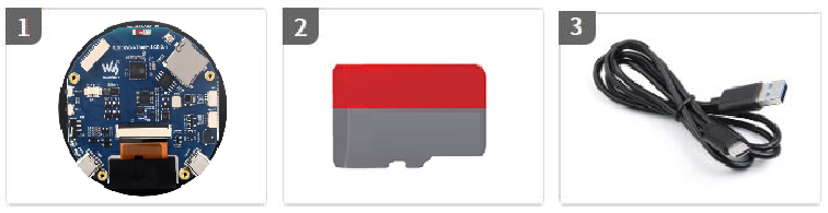
- ESP32-S3-Touch-LCD-2.1 x1
- TF card x 1
- USB cable (Type-A to Type-C) x 1
Working with Arduino
This chapter introduces setting up the Arduino environment, including the Arduino IDE, management of ESP32 boards, installation of related libraries, program compilation and downloading, as well as testing demos. It aims to help users master the development board and facilitate secondary development.

Environment setup
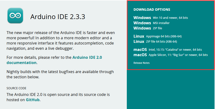
Download and install Arduino IDE
- Click to visit the official website, select the corresponding system and system bit to download.
- Run the installer and install all by default.
Install ESP32 development board
- In order to use the ESP32-related motherboard in the Arduino IDE, the software package of the esp32 by Espressif Systems board must be installed
- According to Board installation requirement, it is generally recommended to use Install Online. If online installation fails, use Install Offline
- For the installation tutorial, please refer to Arduino board manager tutorial
- The esp32 by Espressif Systems development board comes with an offline package. Click here to download: esp32_package_3.0.2_arduino offline package
| Board name | Board installation requirement | Version number requirement |
|---|---|---|
| esp32 by Espressif Systems | "Install Offline" / "Install Online" | ≥3.0.0 |
Install libraries
- When installing Arduino libraries, there are usually two ways to choose from: Install online and Install offline. If the library installation requires offline installation, you must use the provided library file
For most libraries, users can easily search and install them through the online library manager of the Arduino software. However, some open-source libraries or custom libraries are not synchronized to the Arduino Library Manager, so they cannot be acquired through online searches. In this case, users can only manually install these libraries offline. - For library installation tutorial, please refer to Arduino library manager tutorial
- ESP32-S3-Touch-LCD-2.1 library file is stored in the sample program, click here to jump:ESP32-S3-Touch-LCD-2.1 Demo
| Library Name | Description | Version | Library Installation Requirements |
|---|---|---|---|
| LVGL | Graphical library | v8.3.10 | "Install Offline” |
Run the First Arduino Demo
New Project
- Run the Arduino IDE and select
File->New Sketch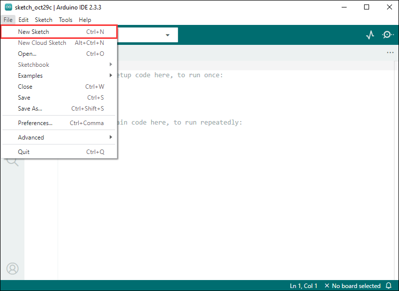
- Enter the code:
void setup() {
  // put your setup code here, to run once:
  Serial.begin(115200);
}

void loop() {
  // put your main code here, to run repeatedly:
  Serial.println("Hello, World!");
  delay(2000);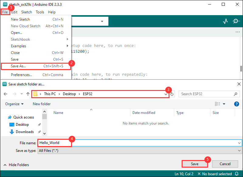
}- Save the project and select
File->Save As.... In the pop-up menu, select the path to save the project, and enter a project name, such as Hello_World, clickSave
Compile and Flash Demos
- Select the corresponding development board, take the ESP32S3 motherboard as an example:
①. Click to select the dropdown menu option Select Other Board and Port;
②. Search for the required development board model esp32s3 dev module and select;
③. Select COM Port;
④. Save the selection.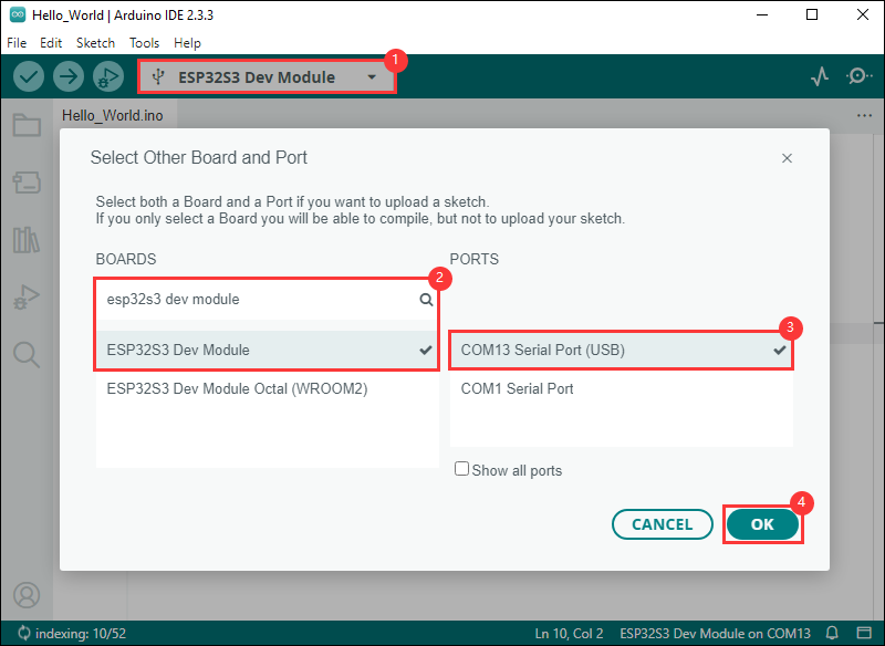
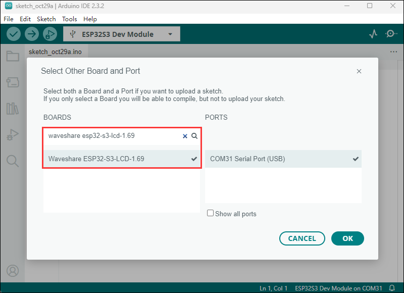
- Some development boards with specified version numbers support direct model selection, for example, "Waveshare ESP32-S3-LCD-1.69":
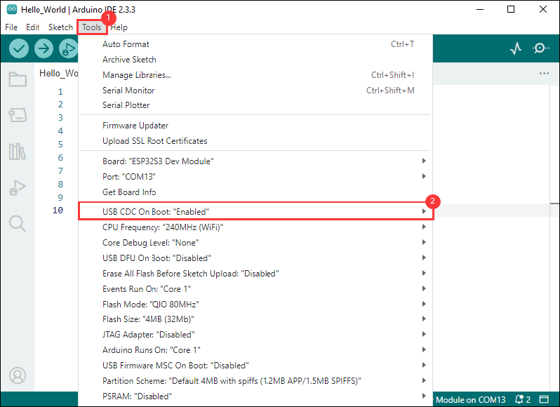
- If the ESP32S3 mainboard only has a USB port, you need to enable USB CDC, as shown in the following diagram:
- Compile and upload the program:
①. Compile the program; ②. Compile and download the program; ③. Download successful.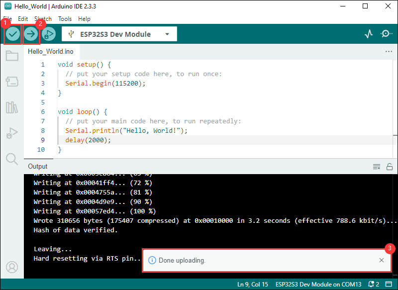
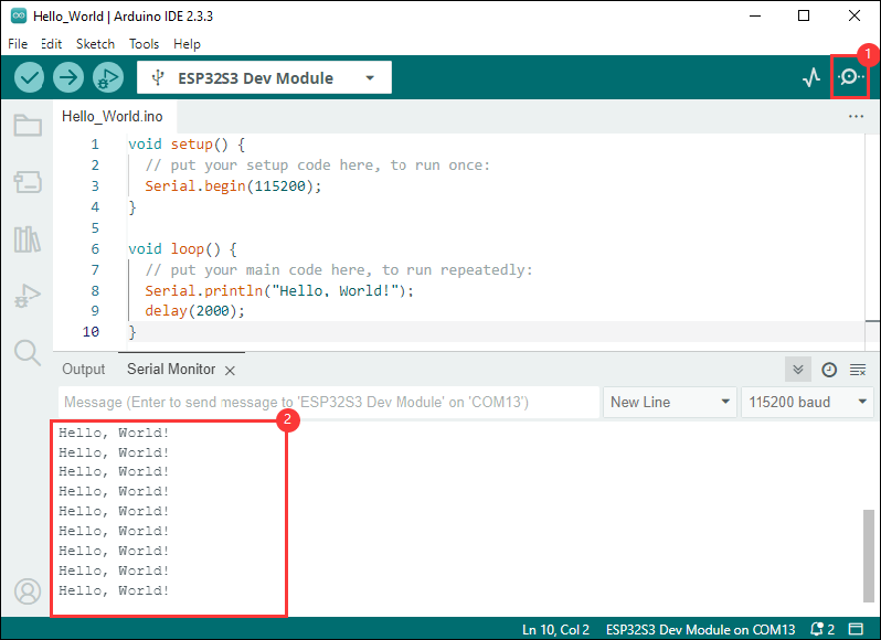
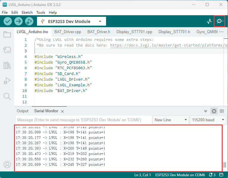
- Open the Serial Monitor window, and the demo will print "Hello World!" every 2 seconds, and the operation is as follows:
Demos

| Demo | Basic Description | Dependency Library |
|---|---|---|
| LVGL_Arduino | Test onboard device functionality | LVGL |
Arduino project parameter settings
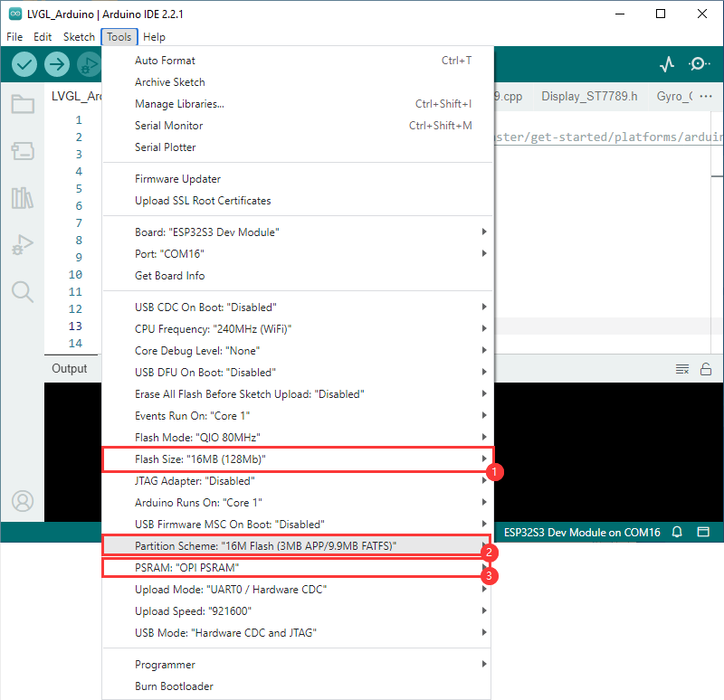
LVGL_Arduino
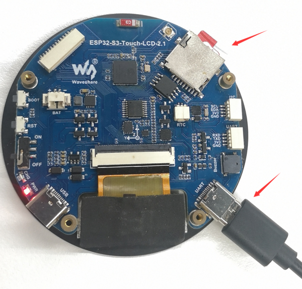
Hardware connection
- Insert the TF card into the development board
- Connect the board to the computer

Code analysis
- setup(): Initialize the onboard devices
- Driver_Init(): Initialize a small device and create a task
Driver_Loop - Driver_Loop(): Drive onboard devices
RTC_Loop(): Process real-time clockQMI8658_Loop(): Read gyroscope dataBAT_Get_Volts(): Get battery voltage
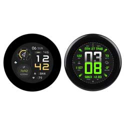
Result demonstration
- LCD screen display
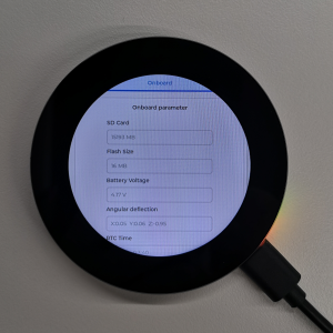
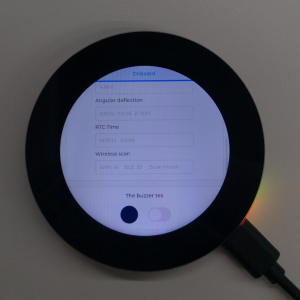
- Parameter description
| Parameter | Function | Description |
| SD Card | Display TF card size | Connect the TF card, if the recognition fails, please format the TF card to FAT32 format (please wait for a while to reset and check again if the recognition fails for the first time) |
| Flash Size | Display Flash size | Current onboard 16MB Flash |
| Battery Voltage | Battery voltage | The battery voltage can be detected when the battery is connected |
| Angular deflection | Display the angular deflection of the board | Display the offset in three directions |
| RTC Time | Display RTC time | Display the current RTC time If the RTC time is not consistent with the current time, because the data cannot be retained in the power-off state, if you need to keep the RTC time normal, you need to connect the RTC battery and update the RTC time. |
| Wireless number | Display the number of scanned WiFi and Bluetooth | When it finishes, display Scan Finish at the end |
| The buzzer test | Buzzer control page | Can control buzzer switch |
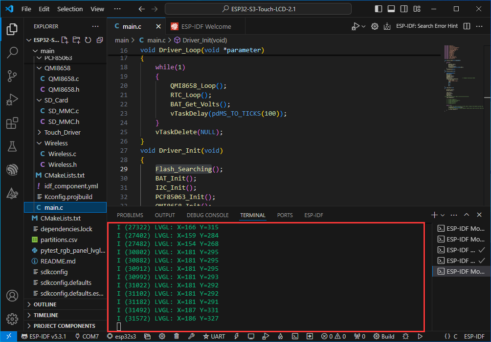
- Swipe on the touch screen, the serial port monitor prints the corresponding position coordinate information
Working with ESP-IDF
This chapter introduces setting up the ESP-IDF environment setup, including the installation of Visual Studio and the Espressif IDF plugin, program compilation, downloading, and testing of example programs, to assist users in mastering the development board and facilitating secondary development.

Environment setup
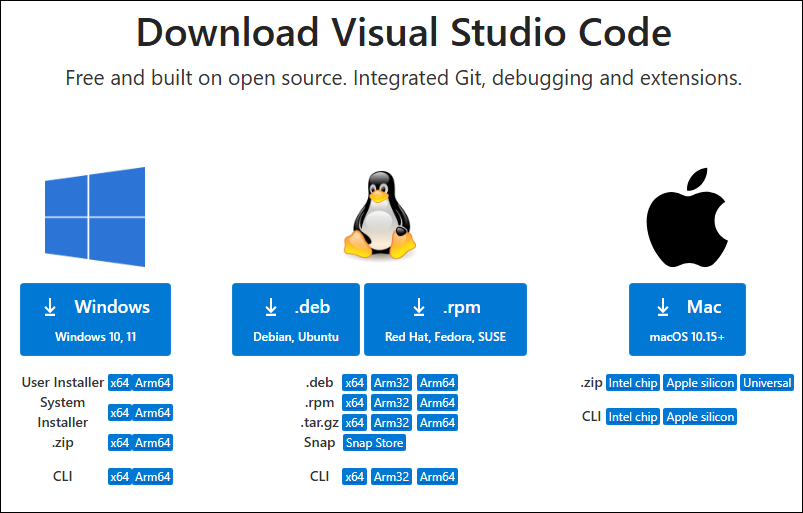
Download and install Visual Studio
- Open the download page of VScode official website, choose the corresponding system and system bit to download
- After running the installation package, the rest can be installed by default, but here for the subsequent experience, it is recommended to check boxes 1, 2, and 3
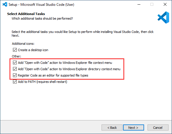
- After the first two items are enabled, you can open VSCode directly by right-clicking files or directories, which can improve the subsequent user experience.
- After the third item is enabled, you can select VSCode directly when you choose how to open it.
Install Espressif IDF Plugin
- It is generally recommended to use Install Online. If online installation fails due to network factor, use Install Offline
- For more information about how to install the Espressif IDF plug-in, see Install Espressif IDF Plugin
| Plugin name | Plugin installation requirements | Version number requirements |
|---|---|---|
| Espressif IDF | "Install Offline" / "Install Online" | ≥5.3.1 |
Run the First ESP-IDF Demo
New Project
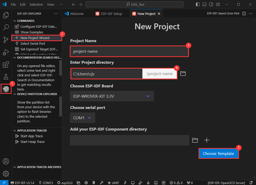
Create Demo
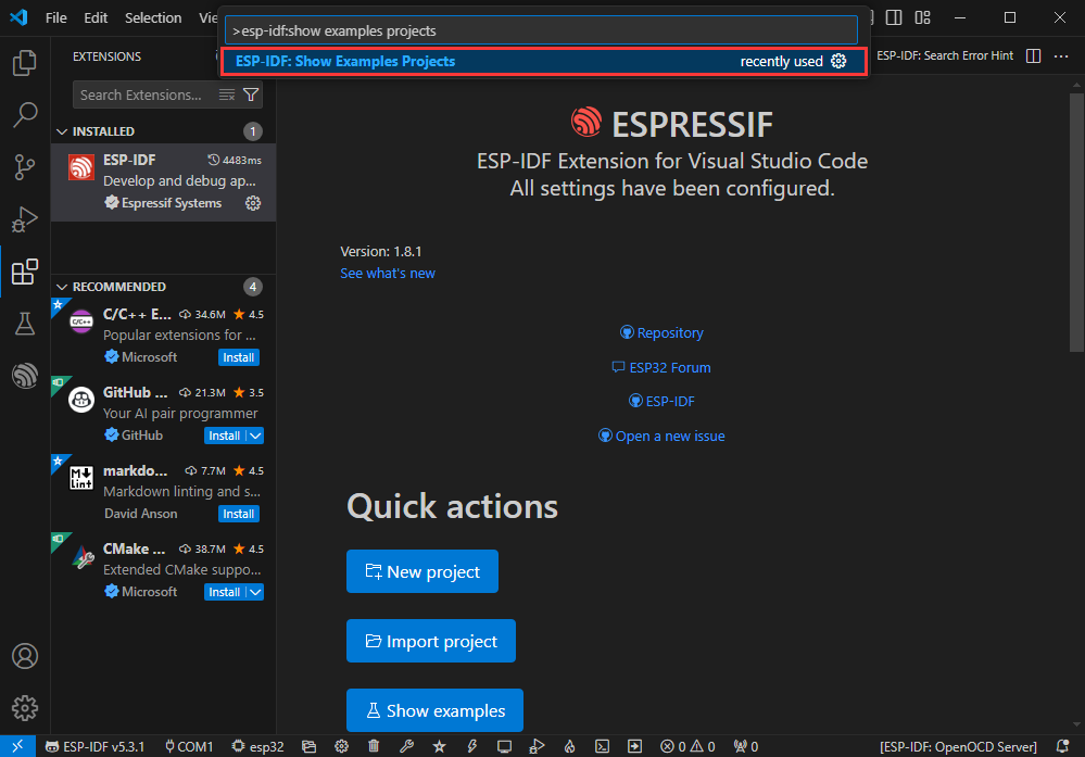
- Using the shortcut F1, enter esp-idf:show examples projects
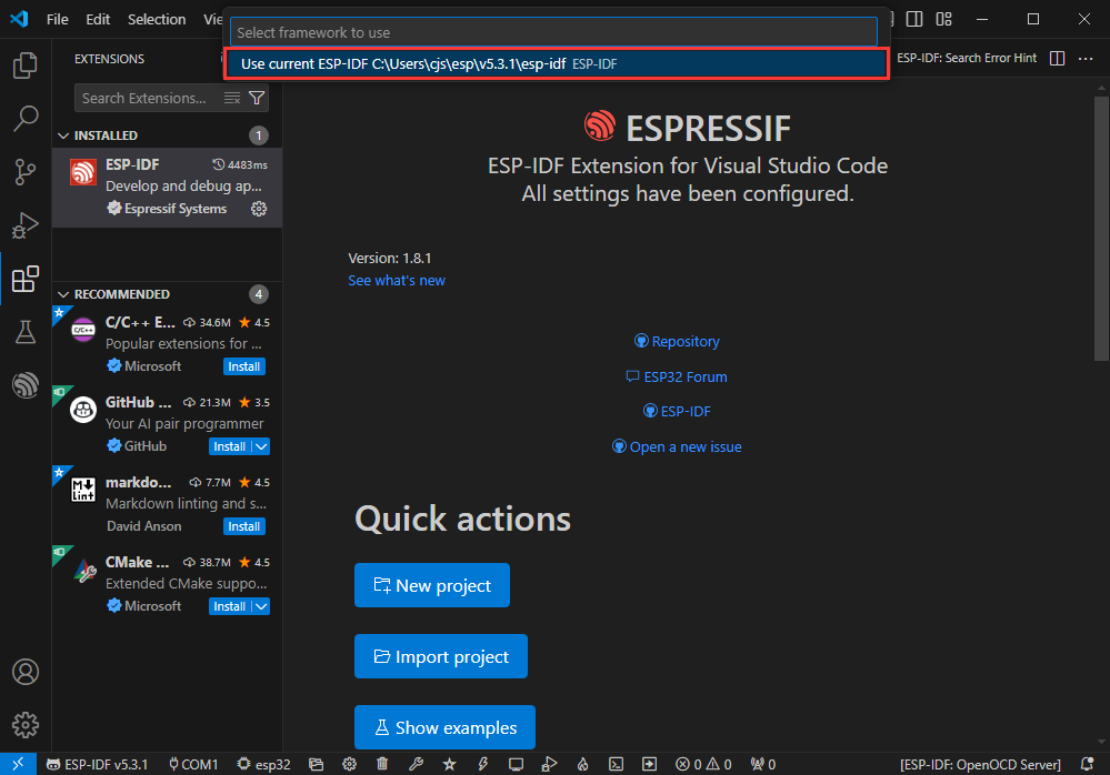
- Select your current IDF version
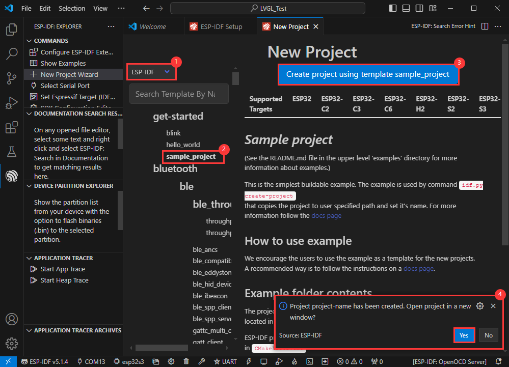
- Take the Hello world demo as an example
①Select the corresponding demo
②Its readme will state what chip the demo applies to (how to use the demo and the file structure are described below, omitted here)
③Click to create the demo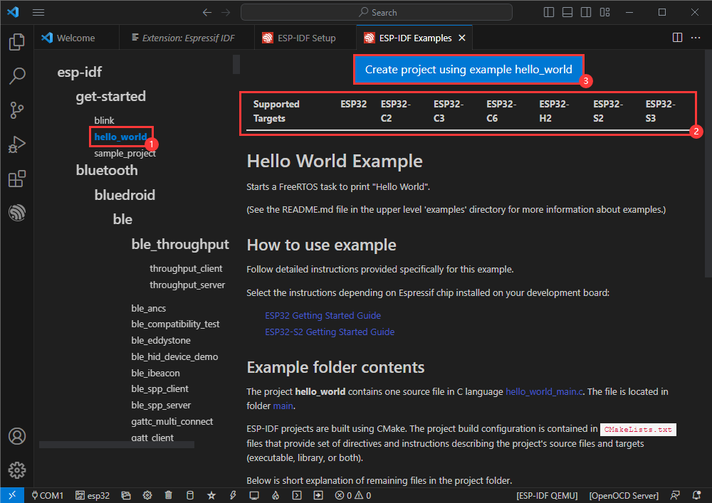
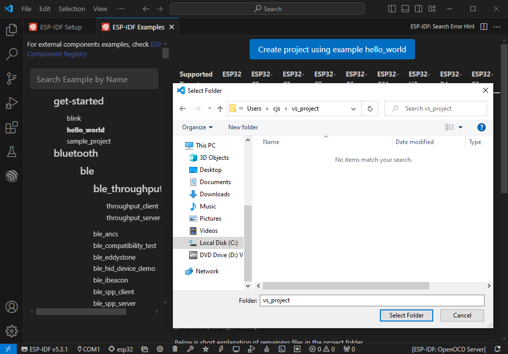
- Select the path to save the demo, and require that the demos cannot use folders with the same name
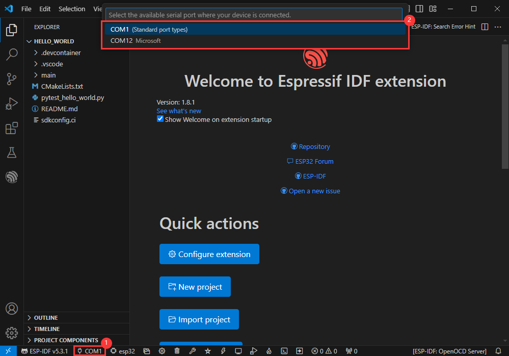
Modify COM Port
- The corresponding COM ports are shown here, click to modify them
- Please select the COM ports according to your device (You can view it from the device manager)
- In case of a download failure, please press the Reset button for more than 1 second or enter download mode, and wait for the PC to recognize the device again before downloading once more
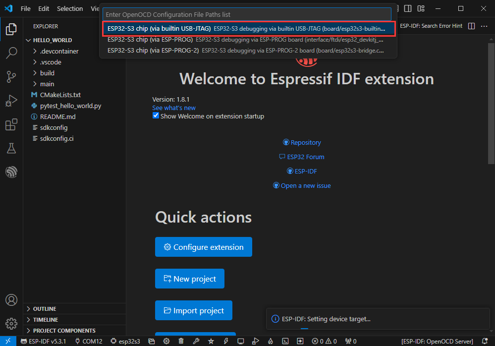
Modify Driver Object
- Select the object we need to drive, which is our main chip ESP32S3
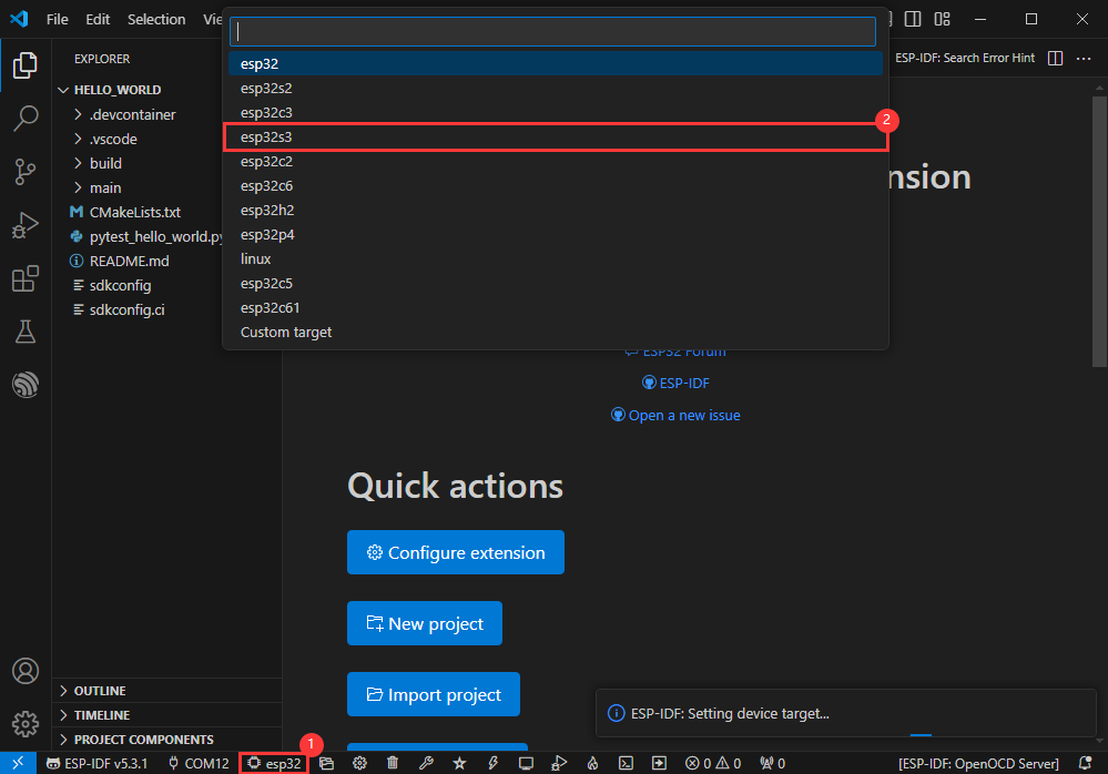
- Choose the path to openocd, it doesn't affect us here, so let's just choose one
Other Status Bar Functions
①.ESP-IDF Development Environment Version Manager, when our project requires differentiation of development environment versions, it can be managed by installing different versions of ESP-IDF. When the project uses a specific version, it can be switched to by utilizing it
②.Device flashing COM port, select to flash the compiled program into the chip
③.Select set-target chip model, select the corresponding chip model, for example, ESP32-P4-NANO needs to choose esp32p4 as the target chip
④.menuconfig, click it to Modify sdkconfig configuration file Project configuration details
⑤.fullclean button, when the project compilation error or other operations pollute the compiled content, you can clean up all the compiled content by clicking it
⑥.Build project, when a project satisfies the build, click this button to compile
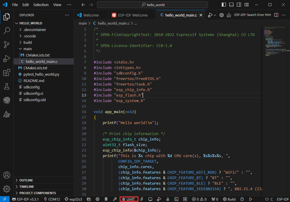
⑦.Current download mode, the default is UART
⑧.flash button, when a project build is completed, select the COM port of the corresponding development board, and click this button to flash the compiled firmware to the chip
⑨.monitor enable flashing port monitoring, when a project passes through Build --> Flash, click this button to view the log of output from flashing port and debugging port, so as to observe whether the application works normally
⑩.Debug
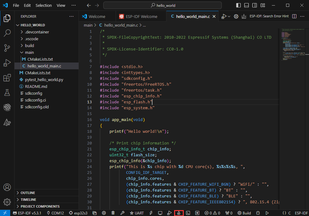
⑪.Build Flash Monitor one-click button, which is used to continuously execute Build --> Flash --> Monitor, often referred to as "little flame"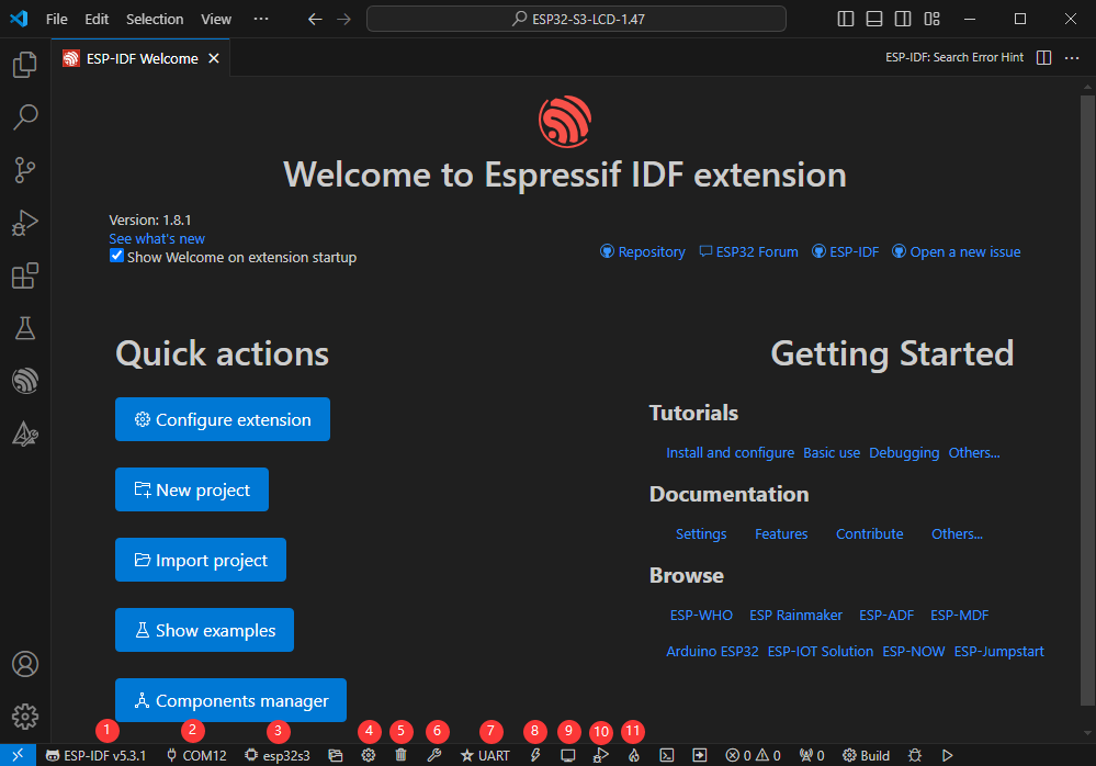
Compile, Flash and Serial Port Monitor
- Click on the all-in-one button we described before to compile, flash and open the serial port monitor
- It may take a long time to compile especially for the first time
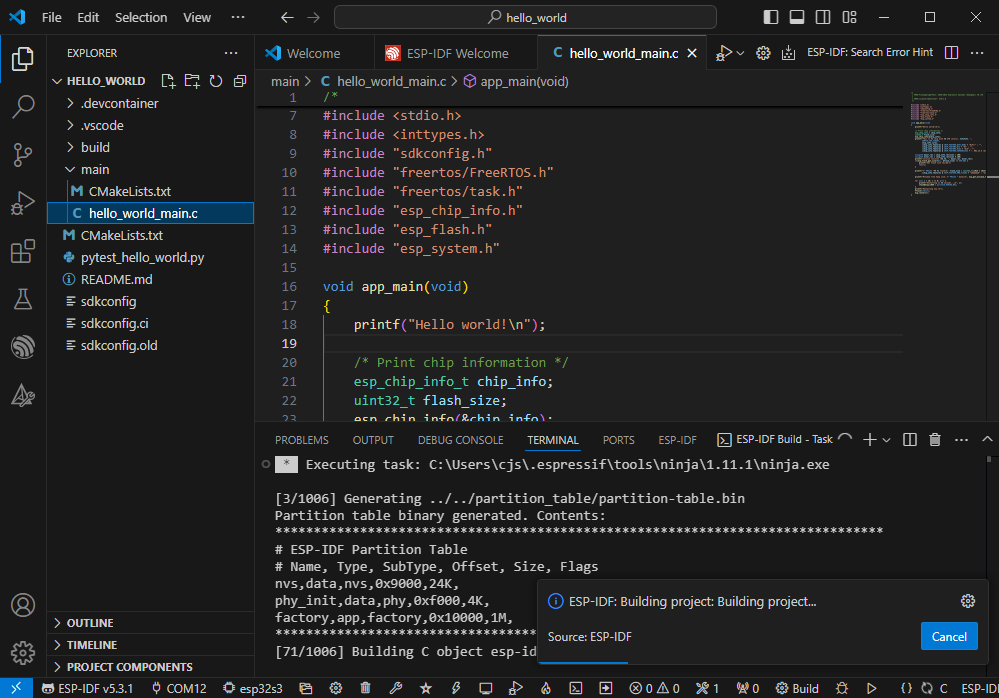
- During this process, the ESP-IDF may take up a lot of CPU resources, so it may cause the system to lag
- If it is the first time to flash the program for a new project, you will need to select the download method, and select UART
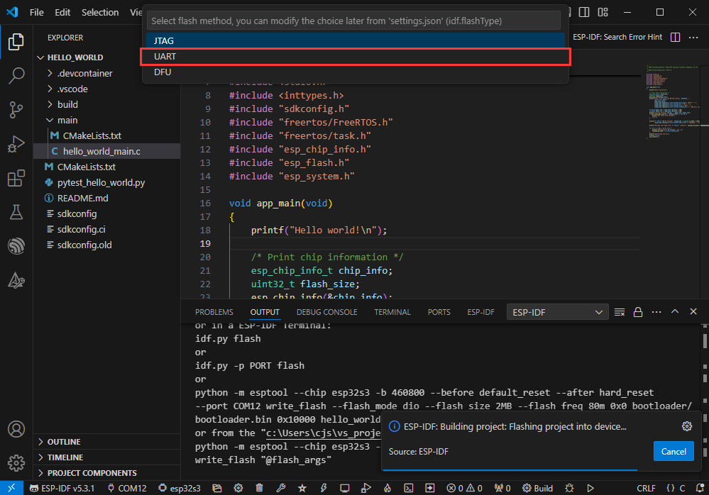
- This can also be changed later in the Download methods section (click on it to pop up the options)
- As it comes with the onboard automatic download circuit, it can be downloaded automatically without manual operation
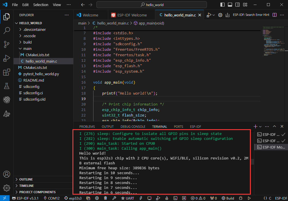
- After successful download, it will automatically enter the serial monitor, you can see the chip output the corresponding information and be prompted to restart after 10S
Use the IDF Demos
Open In the Software
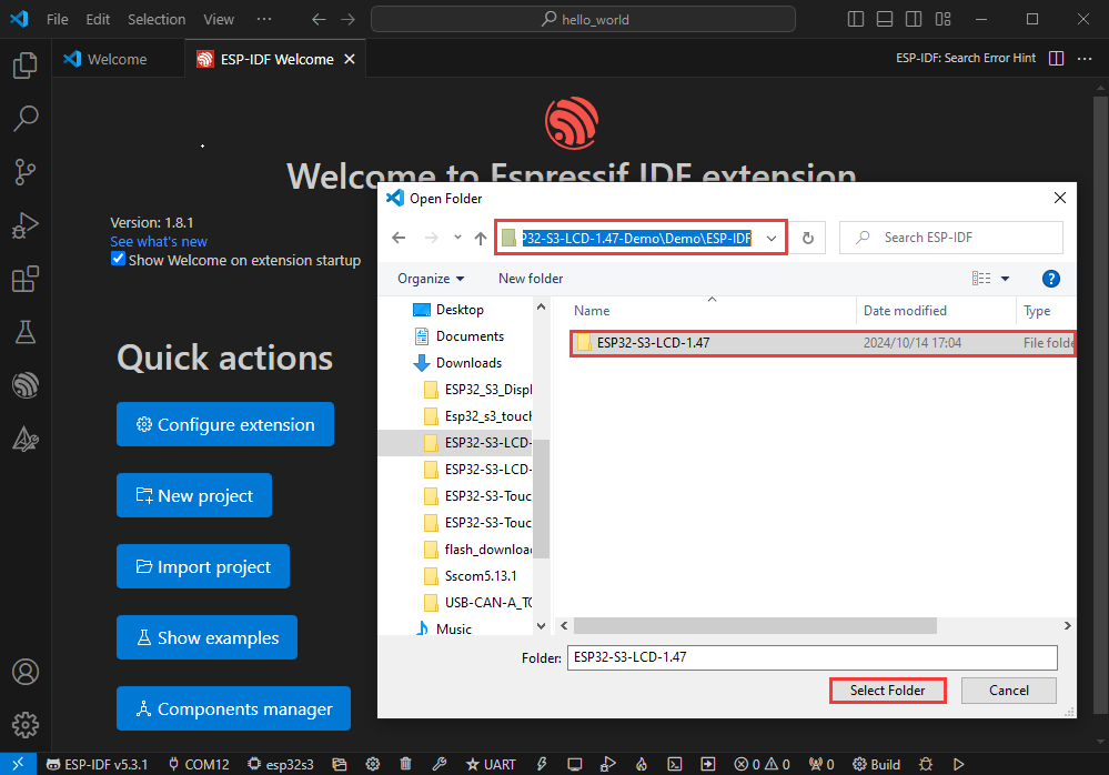
- Open VScode software and select the folder to open the demo
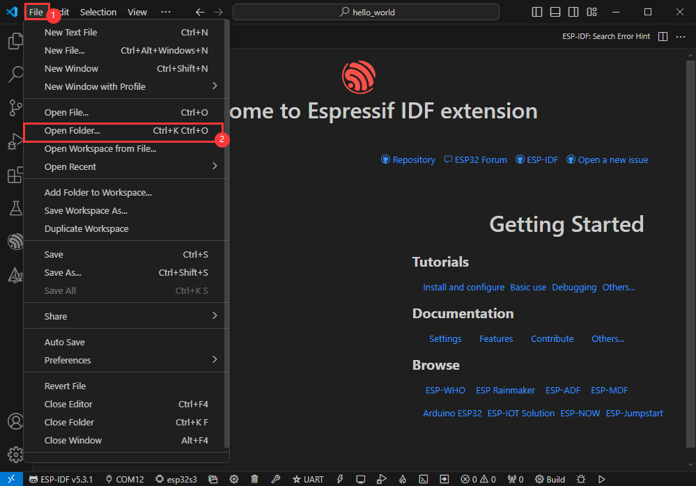
- Select the provided ESP-IDF example and click to select the file (located in the /Demo/ESP-IDF path under demo)
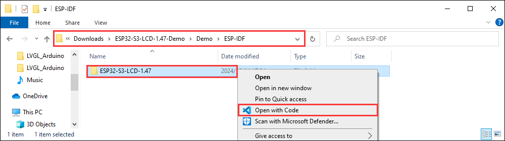
Open from Outside the Software
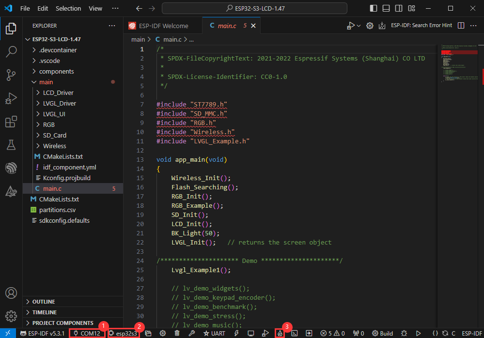
- Select the project directory correctly and open the project, otherwise it will affect the compilation and flashing of subsequent programs
- After connecting the device, select the COM port and model, click below to compile and flash to achieve program control
ESP-IDF Project Details
- Component: The components in ESP-IDF are the basic modules for building applications, each component is usually a relatively independent code base or library, which can implement specific functions or services, and can be reused by applications or other components, similar to the definition of libraries in Python development.
- Component reference: The import of libraries in the Python development environment only requires to "import library name or path", while ESP-IDF is based on the C language, and the importing of libraries is configured and defined through
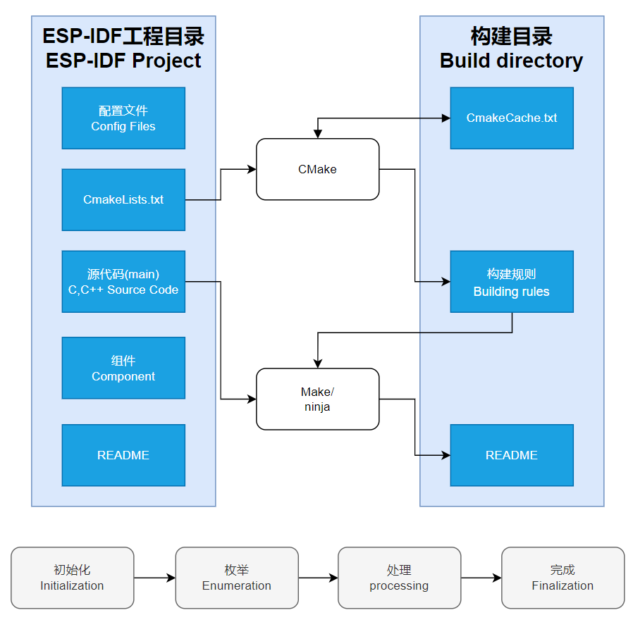
CMakeLists.txt. - The purpose of CmakeLists.txt: When compiling ESP-IDF, the build tool
CMakefirst reads the content of the top-levelCMakeLists.txtin the project directory to read the build rules and identify the content to be compiled. When the required components and demos are imported into theCMakeLists.txt, the compilation toolCMakewill import each content that needs to be compiled according to the index. The compilation process is as follows:
- Component reference: The import of libraries in the Python development environment only requires to "import library name or path", while ESP-IDF is based on the C language, and the importing of libraries is configured and defined through
Demos

| Demo | Basic Description |
|---|---|
| ESP32-S3-Touch-LCD-2.1-Test | Test onboard device functionality |
ESP32-S3-Touch-LCD-2.1-Test
Hardware connection
- Insert the TF card into the development board
- Connect the board to the computer
Code analysis
- setup(): Initialize the onboard devices
- Driver_Init(): Initialize a small device and create a task
Driver_Loop - Driver_Loop(): Drive onboard devices
RTC_Loop(): Process real-time clockQMI8658_Loop(): Read gyroscope dataBAT_Get_Volts(): Get battery voltage
Result demonstration
- LCD screen display


- Parameter description
| Parameter | Function | Description |
| SD Card | Display TF card size | Connect the TF card, if the recognition fails, please format the TF card to FAT32 format (please wait for a while to reset and check again if the recognition fails for the first time) |
| Flash Size | Display Flash size | Current onboard 16MB Flash |
| Battery Voltage | Battery voltage | The battery voltage can be detected when the battery is connected |
| Angular deflection | Display the angular deflection of the board | Display the offset in three directions |
| RTC Time | Display RTC time | Display the current RTC time If the RTC time is not consistent with the current time, because the data cannot be retained in the power-off state, if you need to keep the RTC time normal, you need to connect the RTC battery and update the RTC time. |
| Wireless number | Display the number of scanned WiFi and Bluetooth | When it finishes, display Scan Finish at the end |
| The buzzer test | Buzzer control page | Can control buzzer switch |
- Swipe on the touch screen, the serial port monitor prints the corresponding position coordinate information
Flash Firmware Flashing and Erasing
- The current demo provides test firmware, which can be used to test whether the onboard device functions properly by directly flashing the test firmware
Resources
Schematic diagram
Project diagram
Demo
Datasheets
ESP32-S3
Display
Other components
Software tools
Arduino
VScode
Debugging tool
Other resource links
FAQ
- Click the Reset button for more than 1 second, wait for the PC to re-recognize the device and then download again
- Long press the BOOT button, press RESET at the same time, then release RESET, then release the BOOT button, at this time the module can enter the download mode, which can solve most of the problems that can not be downloaded.
It may be due to Flash blank and the USB port is not stable, you can long-press the BOOT button, press RESET at the same time, and then release RESET, and then release the BOOT button, at this time the module can enter the download mode to flash the firmware (demo) to solve the situation.
- It's normal for the first compilation to be slow, just be patient
- Some AppData folders are hidden by default and can be set to show.
- English system: Explorer->View->Check "Hidden items"
- Chinese system: File Explorer -> View -> Display -> Check "Hidden Items”
- Windows system:
①View through Device Manager: Press the Windows + R keys to open the "Run" dialog box; input devmgmt.msc and press Enter to open the Device Manager; expand the "Ports (COM and LPT)" section, where all COM ports and their current statuses will be listed.
②Use the command prompt to view: Open the Command Prompt (CMD), enter the “mode” command, which will display status information for all COM ports.
③Check hardware connections: If you have already connected external devices to the COM port, the device usually occupies a port number, which can be determined by checking the connected hardware.
- Linux system:
①Use the dmesg command to view: Open the terminal.
①Use the ls command to view: Enter ls /dev/ttyS* or ls /dev/ttyUSB* to list all serial port devices.
③Use the setserial command to view: Enter setserial -g /dev/ttyS* to view the configuration information of all serial port devices.
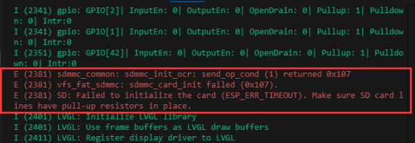
- This situation is that the TF card is not installed or the TF card cannot be recognized. If this situation occurs, please wait for a period of time to reset the device. If it still cannot be resolved, please format the TF card to FAT32 format. If it still fails, please try a different TF card
- Install MAC Driver and flash again.
- Check the schematic diagram for different development boards with Type-C interfaces, and handle the output accordingly:
- For development boards with direct USB output, printf function is supported for printing output. If you want to support output via the Serial function, you will need to enable the USB CDC On Boot feature or declare HWCDC.
- For development boards with UART to USB conversion, both printf and Serial functions are supported for printing output, and there is no need to enable USB CDC On Boot.
- The screen supports 262k colors, due to ESP limitations, RGB565 is used, actually 65k colors
- 0x15,0x20,0x51,0x6B,0x7E
Support
Monday-Friday (9:30-6:30) Saturday (9:30-5:30)
Email: services01@spotpear.com
[Tutorial Navigation]
- Overview
- Usage Instructions
- Working with Arduino
- Working with ESP-IDF
- Environment setup
- Run the First ESP-IDF Demo
- New Project
- Create Demo
- Modify COM Port
- Modify Driver Object
- Other Status Bar Functions
- Compile, Flash and Serial Port Monitor
- Use the IDF Demos
- Demos
- Flash Firmware Flashing and Erasing
- Resources
- FAQ
- Question: After the module downloads the demo and re-downloads it, why sometimes it can't connect to the serial port or the flashing fails?
- Question: Why does the module keep resetting and flicker when viewed the recognition status from the device manager?
- Question: How to deal with the first compilation of the program being extremely slow?
- Question: What should I do if I can't find the AppData folder?
- Question: How do I check the COM port I use?
- Question: Why does ESP-IDF report this error?
- Question: Why does the program flashing fail when using a MAC device?
- Question: Does this development board support multi-touch?
- Question: Why is there no output after successfully flashing the code with no issues?
- Question: RGB screen issue
- Question: How to use SquareLine Studio to design interfaces?
- Question: What addresses are already occupied on the I2C bus?
- Support