




- sales/support
Google Chat:---
- sales
+86-0755-88291180
- sales01
sales@spotpear.com
- sales02
dragon_manager@163.com
- support
tech-support@spotpear.com
- CEO-Complaints
zhoujie@spotpear.com
- Only Tech-Support
WhatsApp:13246739196
- Purchase/Shipping/Refund
WhatsApp:13424403025
- HOME
- >
- ARTICLES
- >
- Common Moudle
- >
- Sensors
A121 Range Sensor User Guide
Overview
Introduction
A121 Range Sensor is based on 60 GHz Pulsed Coherent Radar (PCR) technology, enabling human presence and motion detection, and supports high-precision distance measurement. With configurable detection zones and sensitivity parameters, it possesses excellent anti-interference capability. The module integrates an Arm® Cortex®-M4 MCU (STM32L431CBT6), which can function as a standalone unit running user applications directly on the Acconeer RSS, or communicate with an external host via a register command protocol. It features small size, low power consumption, and easy integration, making it suitable for applications such as human presence detection, proximity sensing, non-contact triggering, and vital sign monitoring.
Usage Scenarios
- Consumer electronics
- Human presence and motion detection
- Material classification and object detection
- Vital sign detection (e.g., breathing, heart rate)
- Gesture control and non-contact buttons
- IoT & smart cities
- Smart parking solutions
- Liquid level/height monitoring
- Liquid surface velocity measurement
- Structural integrity monitoring
- Pedestrian/people flow counting
- Industry & agriculture
- Proximity and distance sensing
- Vibration measurement
- Automotive electronics
- In-cabin monitoring (occupant/status detection)
- Access control and human-machine interaction (HMI)
Operating Principle
The A121 utilizes Pulsed Coherent Radar (PCR) technology. It transmits ultra-short RF pulses and coherently receives the echoes. By leveraging picosecond-level time resolution, it precisely measures the signal round-trip time, achieving sub-millimeter distance accuracy. Simultaneously, phase information allows it to perceive minute displacements and motion. The pulsed operation mode results in very low average power consumption. The highly integrated chip can achieve a range of up to approximately 23 meters without requiring antenna aperture. Since it uses RF electromagnetic waves, it is unaffected by environmental interference such as light, dust, and noise, making it suitable for small, battery-powered devices with low power requirements. Please click this link to understand the working principle of radar.
Specifications
| Product | A121 Range Sensor |
|---|---|
| Operating Frequency Band | 60GHz |
| Modulation | PCR |
| Power Supply | 5V |
| I/O Level | 3.3V |
| Output Interface | USB/UART/I2C |
| Communication Baud Rate | UART: 921.6Kbps |
| I2C: 100K/400K | |
| Range Resolution | 0.03m@25°Profile1 |
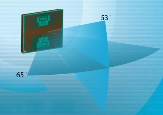
| Field of View | Horizontal: 53° |
| Vertical: 65° | |
| Range Accuracy | 0.03m@Profile1 |
| Maximum Operating Current | 5V 80mA |
| Ambient Temperature | -40 ~ 85℃ |
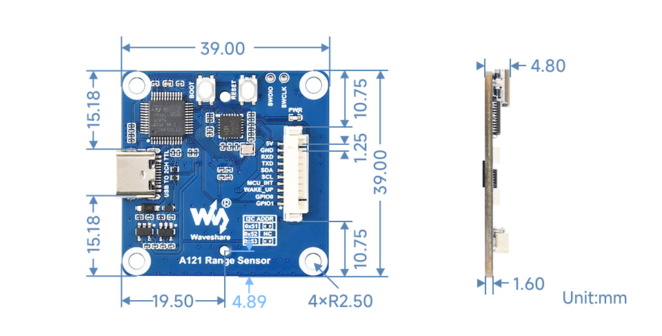
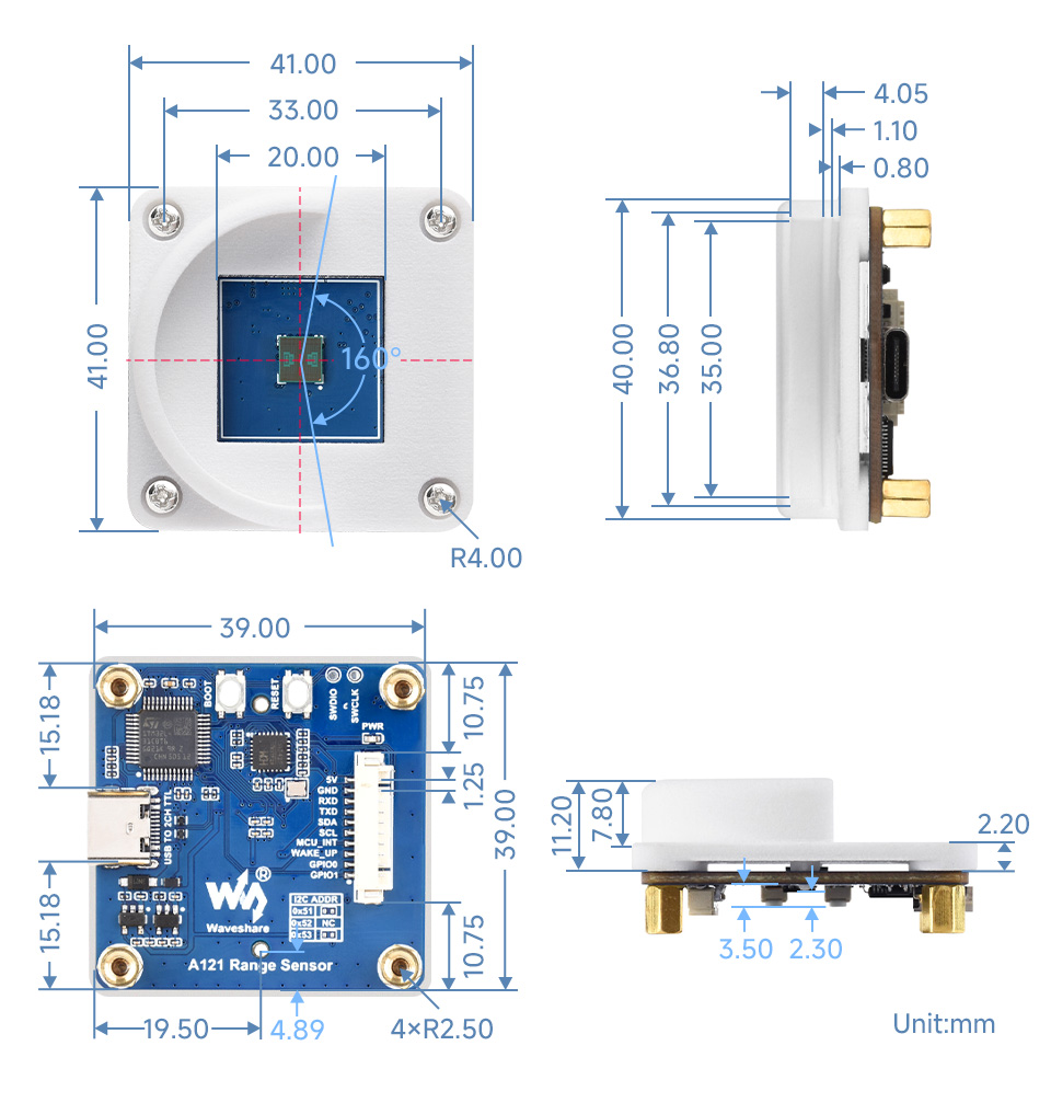
| Dimensions | 39×39mm |
Exploration Tool
- Helps you quickly start testing and evaluating our sensor to meet your use case requirements. It will also guide you to find the optimal sensor settings and assist in fine-tuning the final product's data processing. The following runs on a Windows PC. For Linux, please refer to this link.
- Click to download the host computer tool
- Click to download the firmware, which is the firmware for the Exploration Tool by default.
Getting Started
- Extract the portable_exploration_tool.zip file in a suitable location.
- Double-click the update.bat script. This update process takes a long time, so please wait patiently. If it fails, check your network connection and run update.bat again.
- After the update is complete, double-click the run_app.bat script to launch the Exploration Tool application. In the pop-up "Acconeer Exptool Launcher" window, click A121.
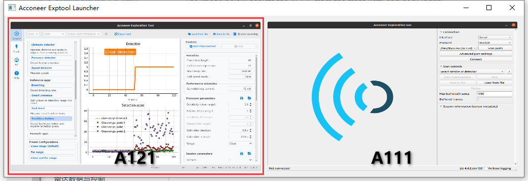
- Connect the module to your computer using a Type-C cable. Find the ports in Device Manager. They are listed under Ports (COM & LPT) as USB-Enhanced -SERIAL-A CH342 and USB-Enhanced -SERIAL-B CH342. If not found, you may need to reinstall the driver
- When connecting the module to the Exploration Tool application, use the USB-Enhanced -SERIAL-A CH342 port, then click Connect. Once successfully connected, you can proceed with testing. Each test has a documentation link next to it; click to view if you are unsure.
Flashing Firmware
- Click Flash in the Exploration Tool
- Select XM125
- Check the box for Show all devices
- Select the USB-Enhanced -SERIAL-A CH342 port. You can use online download or a local file
- Click Flash on the next screen. Follow the prompts to enter boot mode, and the firmware flashing will begin.
- Done indicates successful flashing.
Firmware Description
- The A121 Range Sensor provides comprehensive firmware variants, including for the host computer tool, UART, and I2C interfaces, as described below:
- UART firmware outputs information via the USB-Enhanced -SERIAL-B CH342 port or the serial pins on the board
- I2C firmware outputs information via the I2C pins and is used in conjunction with the BUSY pin. The slave address defaults to 0x52 and can be adjusted to 0x51 or 0x53 via resistors on the board
| Demo | Basic Description |
|---|---|
| Exploration Tool | |
| acc_exploration_server_a121 | Flash this firmware to connect with the Exploration Tool |
| UART | |
| Getting started | |
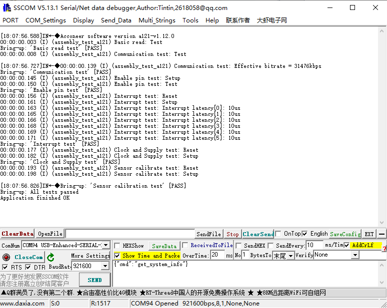
| example_bring_up | Basic bring-up example for quick start and application development |
| example_control_helper | Control helper example demonstrating basic usage of the control interface |
| example_detector_distance | Basic distance detector example |
| example_detector_presence | Basic presence detector example |
| example_service | Basic Service interface example |
| Advanced control | |
| example_detector_distance_calibration_caching | Distance detection + calibration result caching |
| example_detector_distance_low_power_hibernate | Distance detection with low-power hibernate mode |
| example_detector_distance_low_power_off | Distance detection with low-power off mode |
| example_detector_distance_with_iq_data_print | Distance detection with IQ raw data printing |
| example_detector_presence_low_power_hibernate | Presence detection with low-power hibernate mode |
| example_detector_presence_low_power_off | Presence detection with low-power off mode |
| example_detector_presence_multiple_configurations | Presence detection with multiple configuration switching |
| example_detector_presence_with_iq_data_print | Presence detection with IQ raw data printing |
| example_service_calibration_caching | Calibration caching example in Service mode |
| example_service_low_power_sensor_disable | Service low power: sensor disable |
| example_service_low_power_sensor_hibernate | Service low power: sensor hibernate |
| example_service_multiple_configurations | Service multiple configurations example |
| example_service_sensor_disable | Service: sensor disable |
| example_service_sensor_hibernate | Service: sensor hibernate |
| example_service_sensor_off | Service: sensor off |
| example_service_subsweeps | Service: subsweeps configuration example |
| Processing | |
| example_processing_amplitude | Amplitude processing example |
| example_processing_coherent_mean | Coherent mean processing example |
| example_processing_noncoherent_mean | Non-coherent mean processing example |
| example_processing_peak_interpolation | Peak interpolation processing example |
| example_processing_static_presence | Static presence detection processing example |
| example_processing_subtract_adaptive_bg | Adaptive background subtraction processing example |
| Troubleshooting | |
| example_diagnostic_test | Diagnostic test example for hardware/communication troubleshooting |
| Reference Apps | |
| ref_app_breathing | Breathing detection reference application |
| ref_app_parking | Parking/spot detection reference application |
| ref_app_smart_presence | Smart presence detection reference application |
| ref_app_tank_level | Level/liquid level detection reference application |
| ref_app_touchless_button | Touchless button reference application |
| Example Apps | |
| example_cargo | Cargo utilization and human presence detection reference example |
| example_hand_motion_detection | Example for detecting hand motion or gestures |
| example_surface_velocity | Example for measuring the velocity of a moving surface |
| example_vibration | Example for detecting and analyzing vibration characteristics |
| example_waste_level | Example for measuring waste or material level height |
| I2C | |
| i2c_distance_detector | I2C interface distance detector basic example |
| i2c_example_cargo | I2C interface cargo detection example |
| i2c_presence_detector | I2C interface presence detector basic example |
| i2c_ref_app_breathing | I2C interface breathing detection reference application |
Lens Description
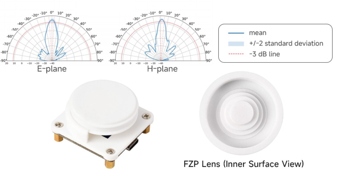
- The reference lenses we provide are made of 3301PA material, featuring a solid monolithic structure design with good mechanical strength and stability. The lens assembly consists of the following key components:
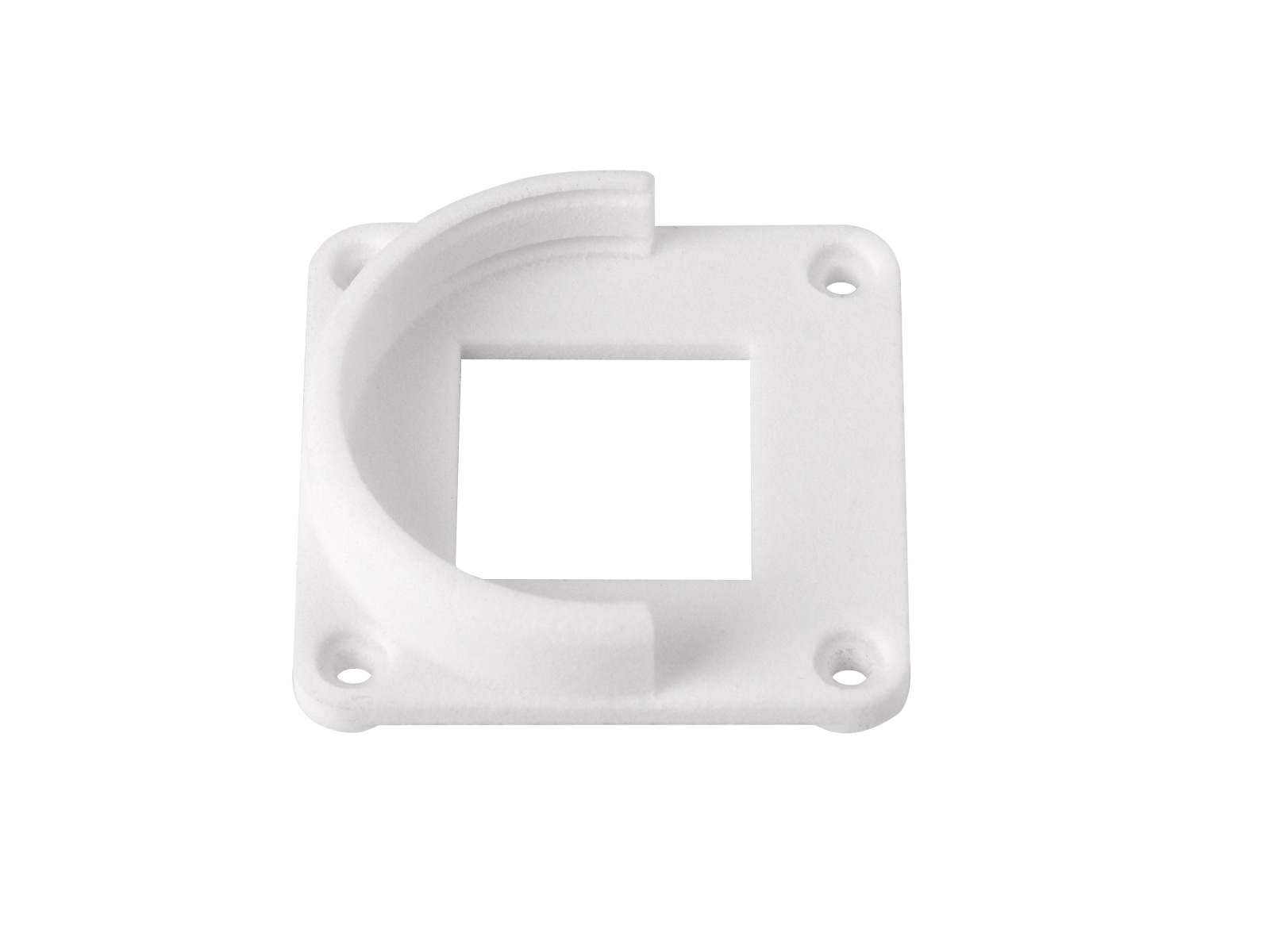
1. Lens Holder
Used to secure the PCB and lens assembly, ensuring the relative positional accuracy between the lens and the chip, thereby improving system assembly stability and consistency.
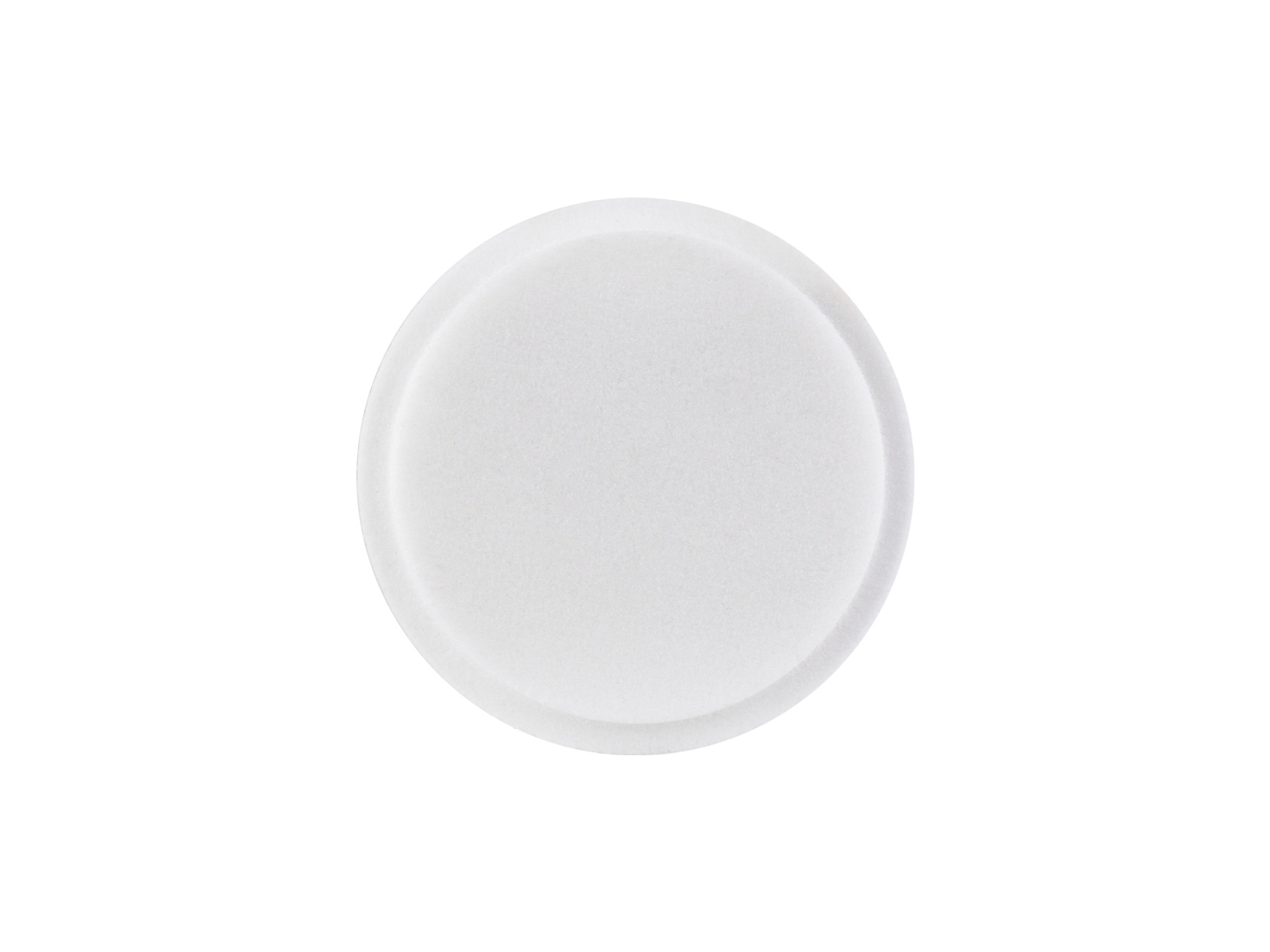
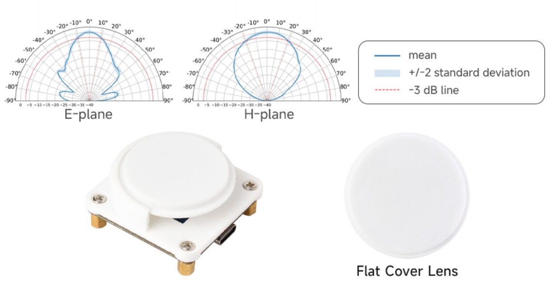
2. Flat Cover
Primarily used to protect the photosensitive chip surface from scratches or contamination during assembly, transportation, or use. It does not introduce optical distortion to the imaging.
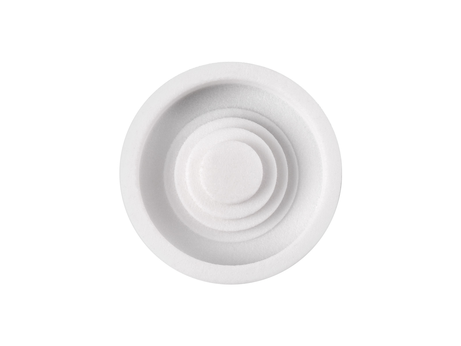
3. Fresnel Zone Plate
Achieves light focusing through phase modulation principles. It effectively reduces lens thickness and weight while maintaining focusing capability, making it suitable for applications with structural height constraints.
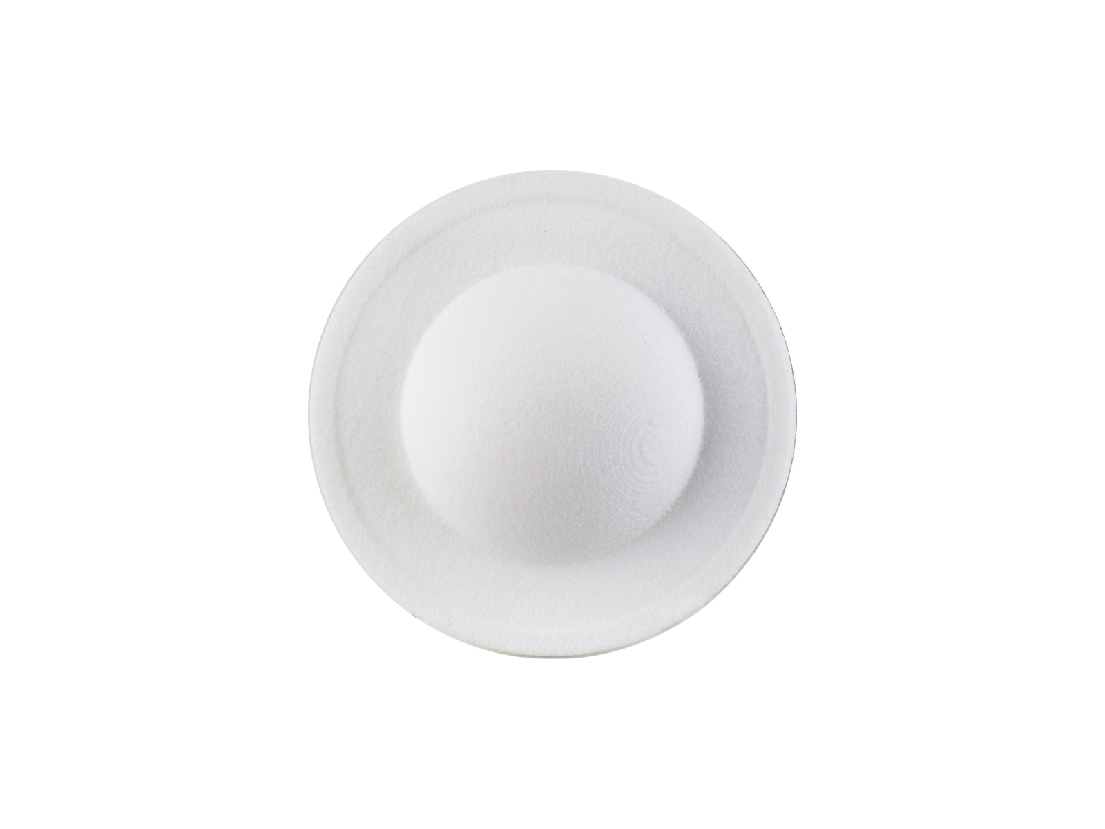
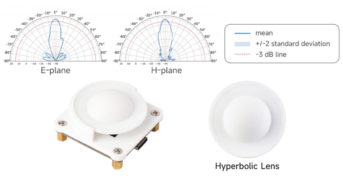
4. Hyperbolic Lens
Focuses incident light through refraction principles, effectively improving imaging quality, focusing accuracy, and image clarity of the optical system.
Detection Range
- Flat Cover
- Hyperbolic Lens
- Fresnel Zone Plate
Other Information
- For information on how to configure the A121 and other parameter descriptions, please click this link.
Dimensions
UART Firmware Usage
- This section briefly explains the effects and usage of UART firmware. The default baud rate is 921600.
- To test different functions, you need to flash different firmware. For flashing instructions, refer to the Flashing Firmware section above.
Hardware Connection
- After flashing the firmware, connect the module to the computer via a Type-C cable. You can view information by selecting the USB-Enhanced -SERIAL-B CH342 port or through the TX pin on the MX1.25 connector.
Getting Started
- example_bring_up effect:
- example_control_helper effect:
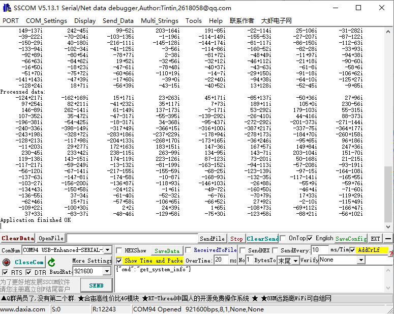
- example_detector_distance effect:
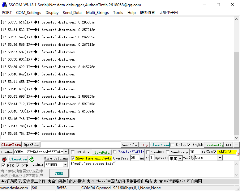
- example_detector_presence effect:
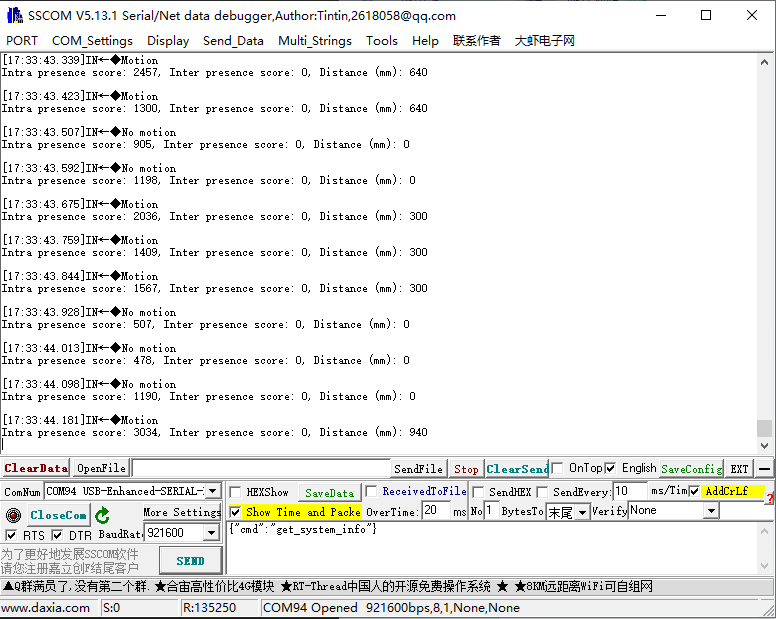
- example_service effect:
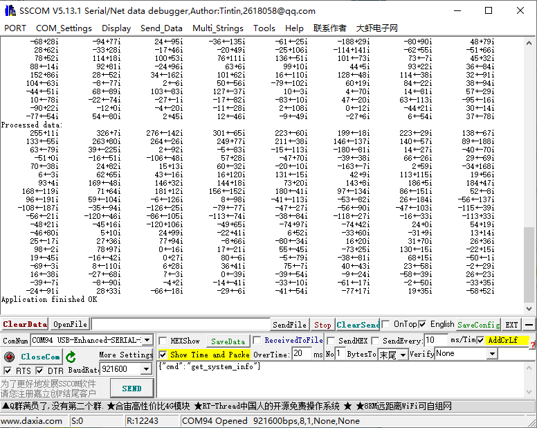
Reference Apps
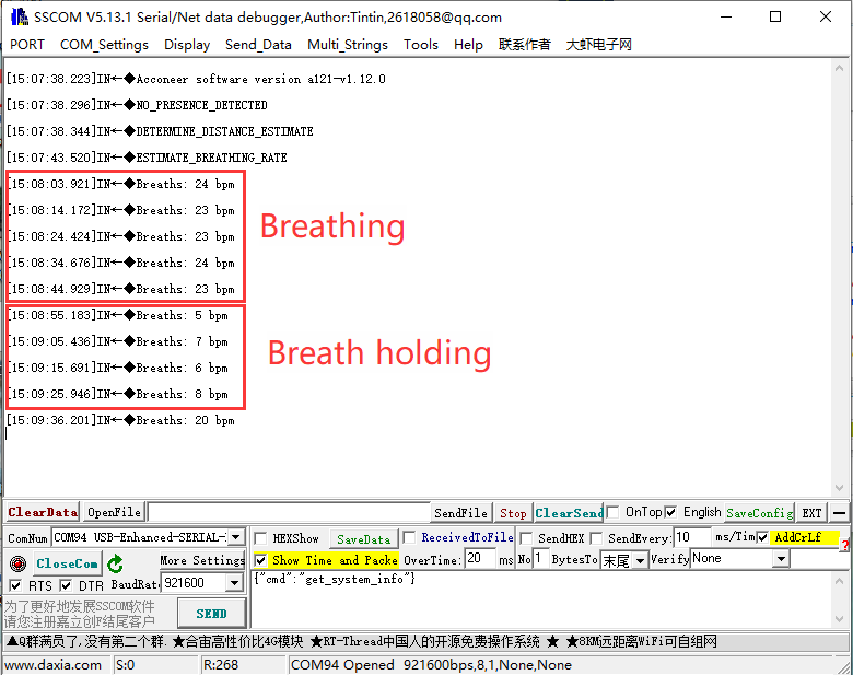
- ref_app_breathing effect:
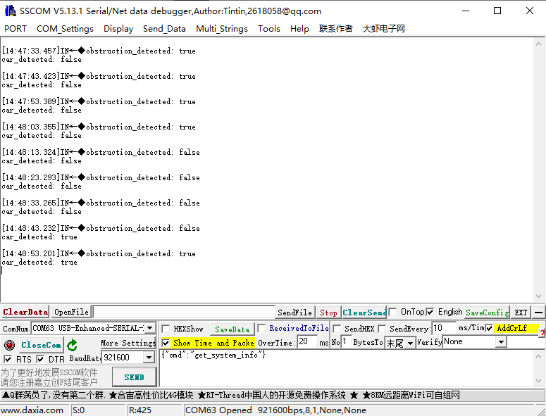
- ref_app_parking effect:
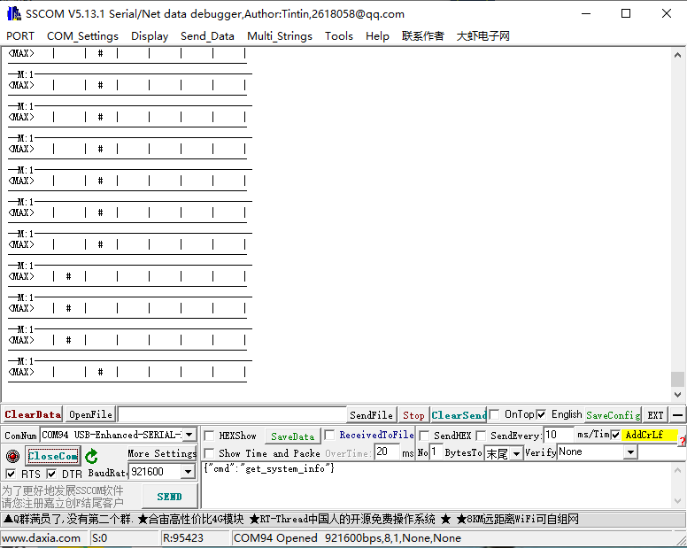
- ref_app_smart_presence effect:
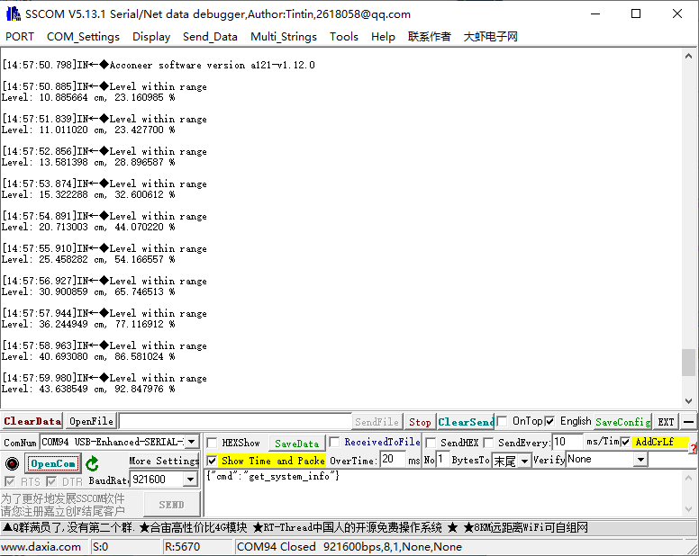
- ref_app_tank_level effect:
- ref_app_touchless_button effect:
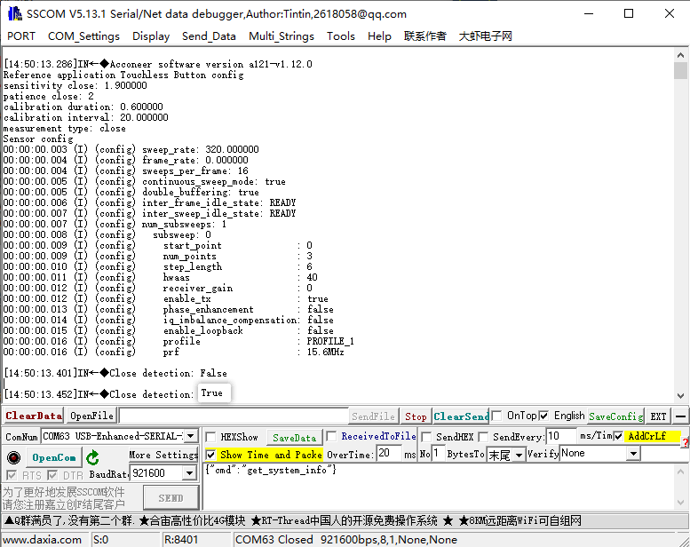
Example Apps
- example_cargo effect:
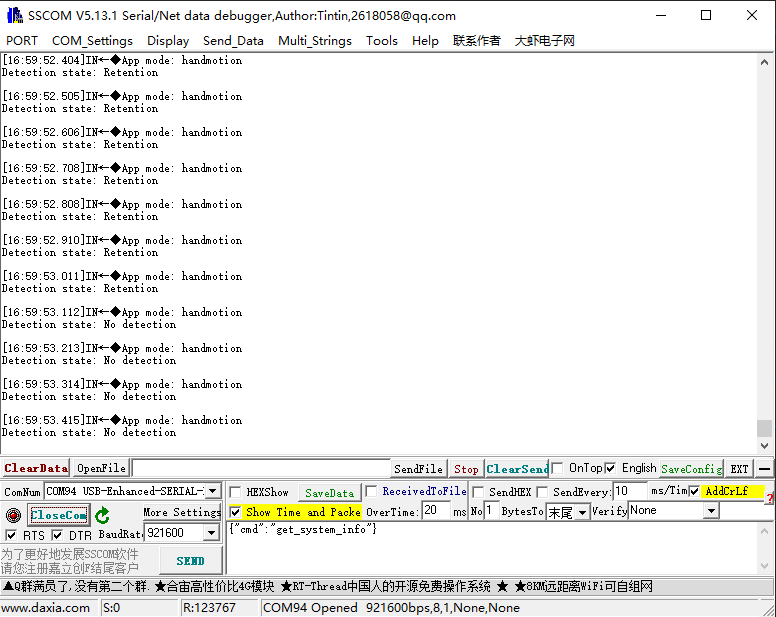
- example_hand_motion_detection effect:
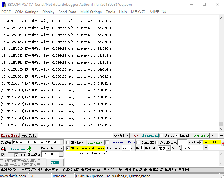
- example_surface_velocity effect:
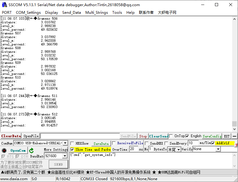
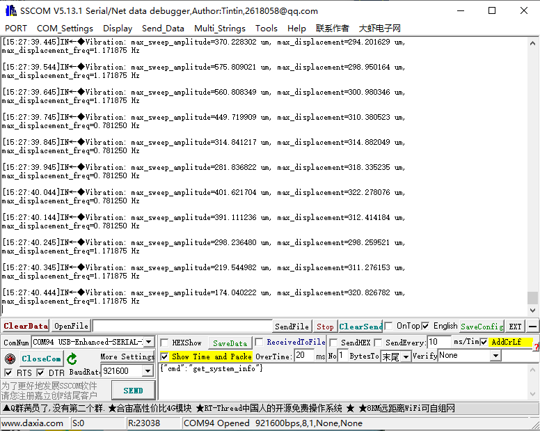
- example_vibration effect:
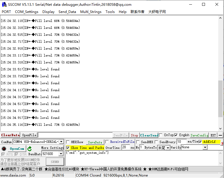
- example_waste_level effect:
I2C Firmware Usage
- This section briefly explains the effects and usage of I2C firmware. The default slave address is 0x52.
- To test different functions, you need to flash different firmware. For flashing instructions, refer to the Flashing Firmware section above.
Working with Raspberry Pi
Enable Raspberry Pi I2C
- Enter the command in the Raspberry Pi terminal: sudo raspi-config nonint do_i2c 0
Hardware Connection
To access the Raspberry Pi I2C, refer to the following: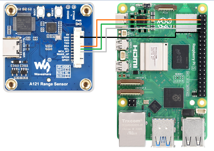
Install Library
- C
git clone https://github.com/WiringPi/WiringPi.git
cd WiringPi/
./build debian
# Proceed to the next step based on the generated filename
sudo mv debian-template/wiringpi_*.*_arm64.deb .
sudo apt install ./wiringpi_*.*_arm64.deb
# Check if the installation was successful (a version number will appear)
gpio -v
- Python
sudo apt install python-smbus2
Download Demo
cd ~
wget https://files.waveshare.com/wiki/A121_Range_Sensor/A121_Range_Sensor_Demo.zip
unzip A121_Range_Sensor_Demo.zip
cd A121_Range_Sensor_Demo/
Run C Demo
cd ~/A121_Range_Sensor_Demo/Raspberrypi/c/
# Choose the compilation target based on the flashed firmware. Options are:
make A121_APP=BREATHING -B
make A121_APP=CARGO -B
make A121_APP=PRESENCE -B
make A121_APP=DISTANCE -B
#Run the demo
./main
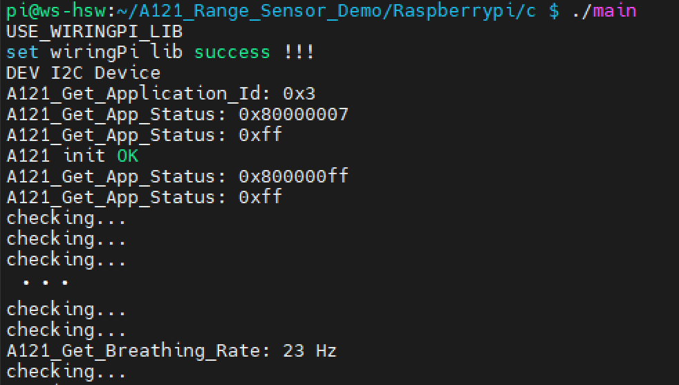
- The terminal will output the relevant information, as shown below:
- BREATHING:
- CARGO:
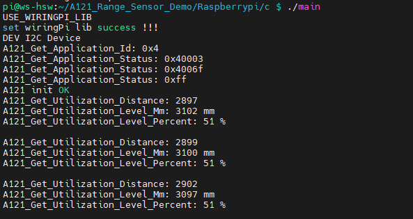
- PRESENCE:
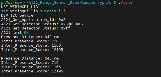
- DISTANCE:
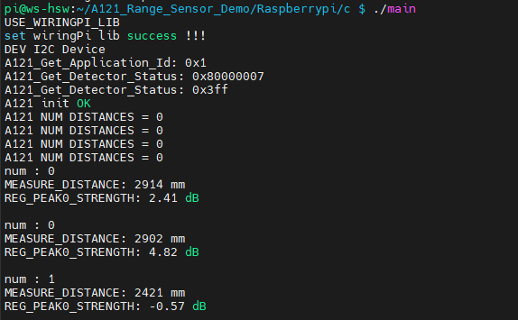
Run Python Demo
cd ~/A121_Range_Sensor_Demo/Raspberrypi/python/example
# Choose the compilation target based on the flashed firmware. Options are:
python main.py breathing
python main.py cargo
python main.py presence
python main.py distance
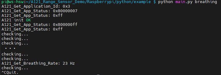
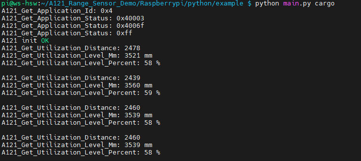
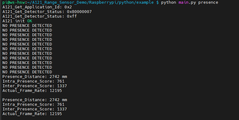
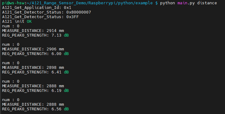
- The terminal will output the relevant information, as shown below:
- BREATHING:
- CARGO:
- PRESENCE:
- DISTANCE:
Working with ESP32S3
- For ESP32S3 environment setup and basic usage, please refer to this link.
- After setting up the environment, you can connect the sensor and download the Demo
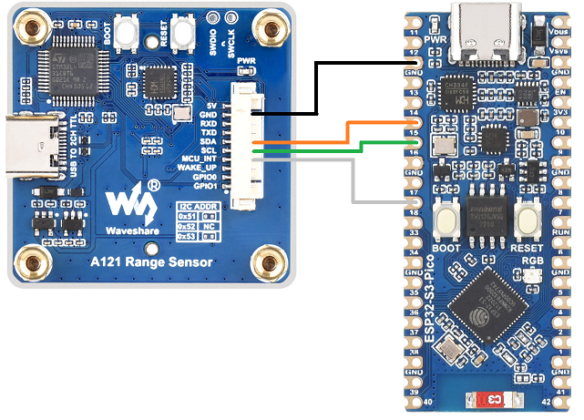
Hardware Connection
- Refer to the following diagram for connection:
Arduino esp32 Demos
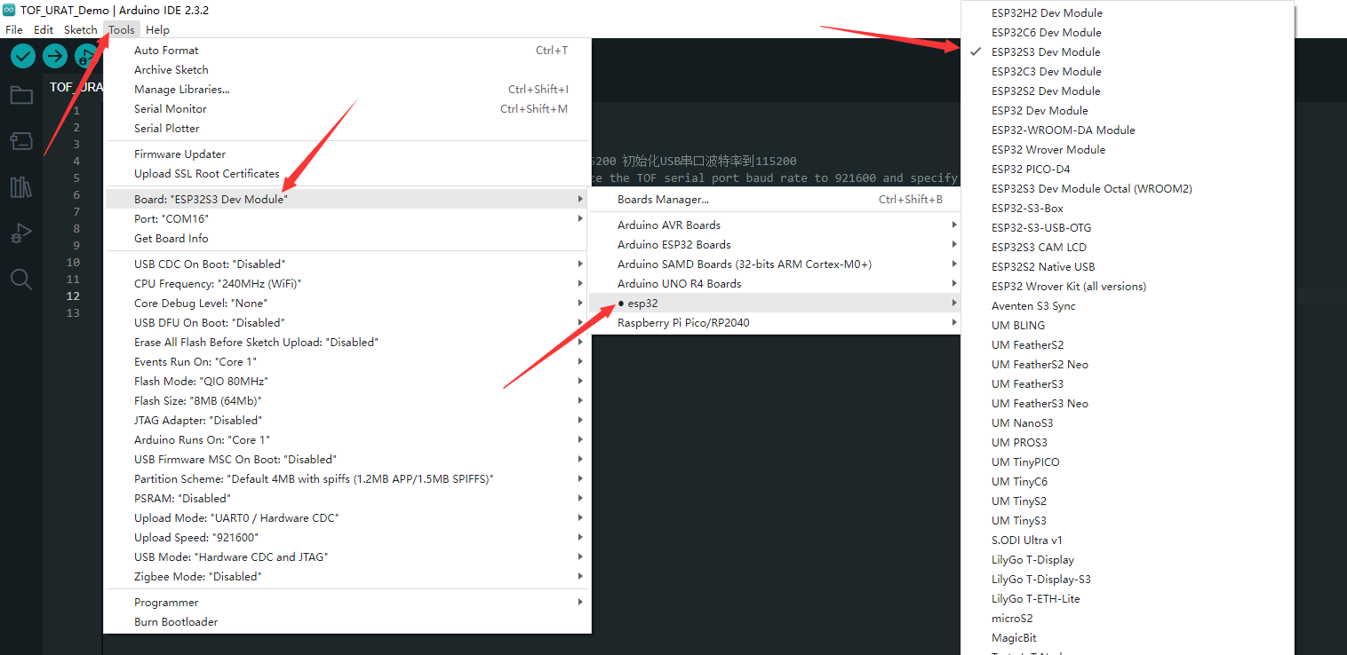
- Navigate to A121_Range_Sensor_Demo\ESP32S3\Arduino\*, where * is the demo corresponding to the firmware. Double-click the .ino file.
- Select development board:
- Select the port of the ESP32S3, and then compile and upload it
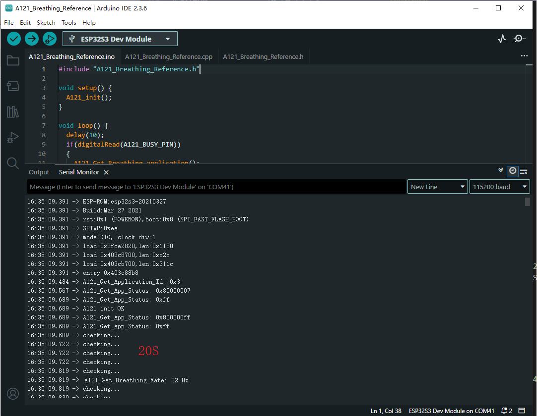
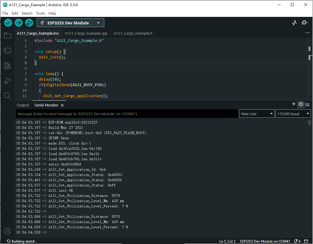
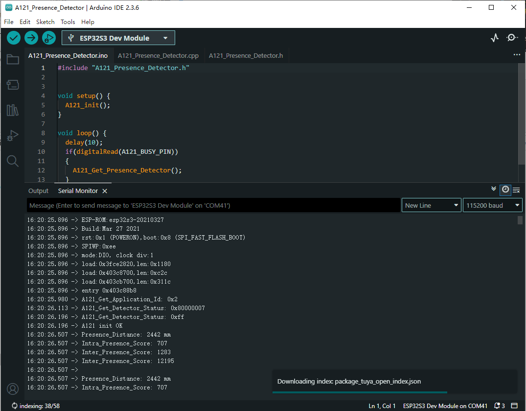
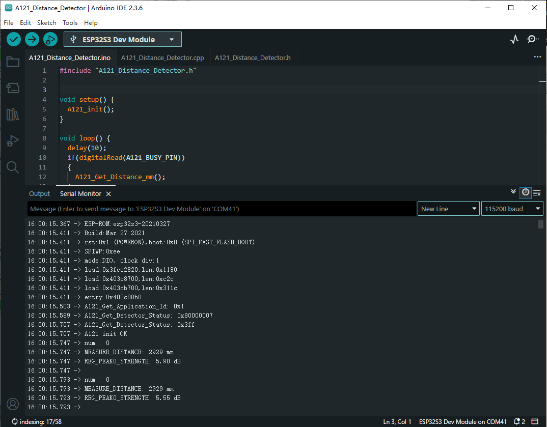
- After the upload is completed, open the serial port monitor, and the relevant information will be output, as shown below:
- BREATHING:
- CARGO:
- PRESENCE:
- DISTANCE:
Micropython Demos
- Navigate to A121_Range_Sensor_Demo\ESP32S3\micropython. Double-click the .py file corresponding to the firmware.
- Select development board:
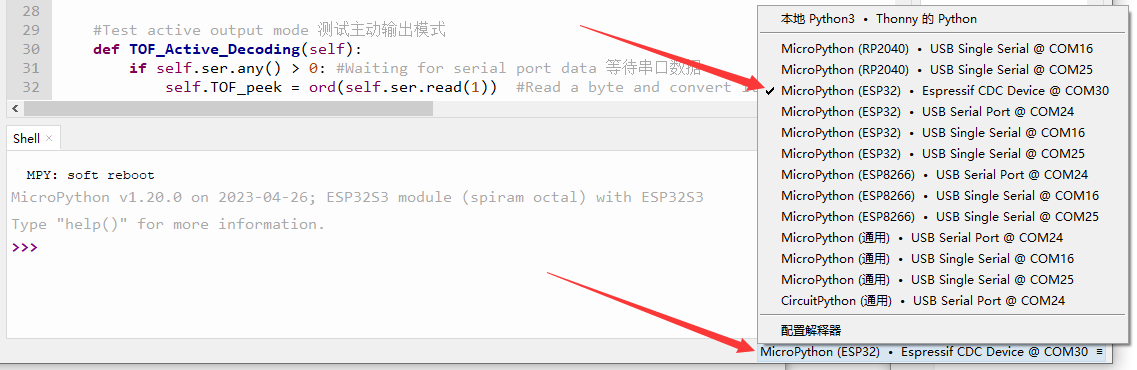
- Select the port of the ESP32S3, and then run the demo
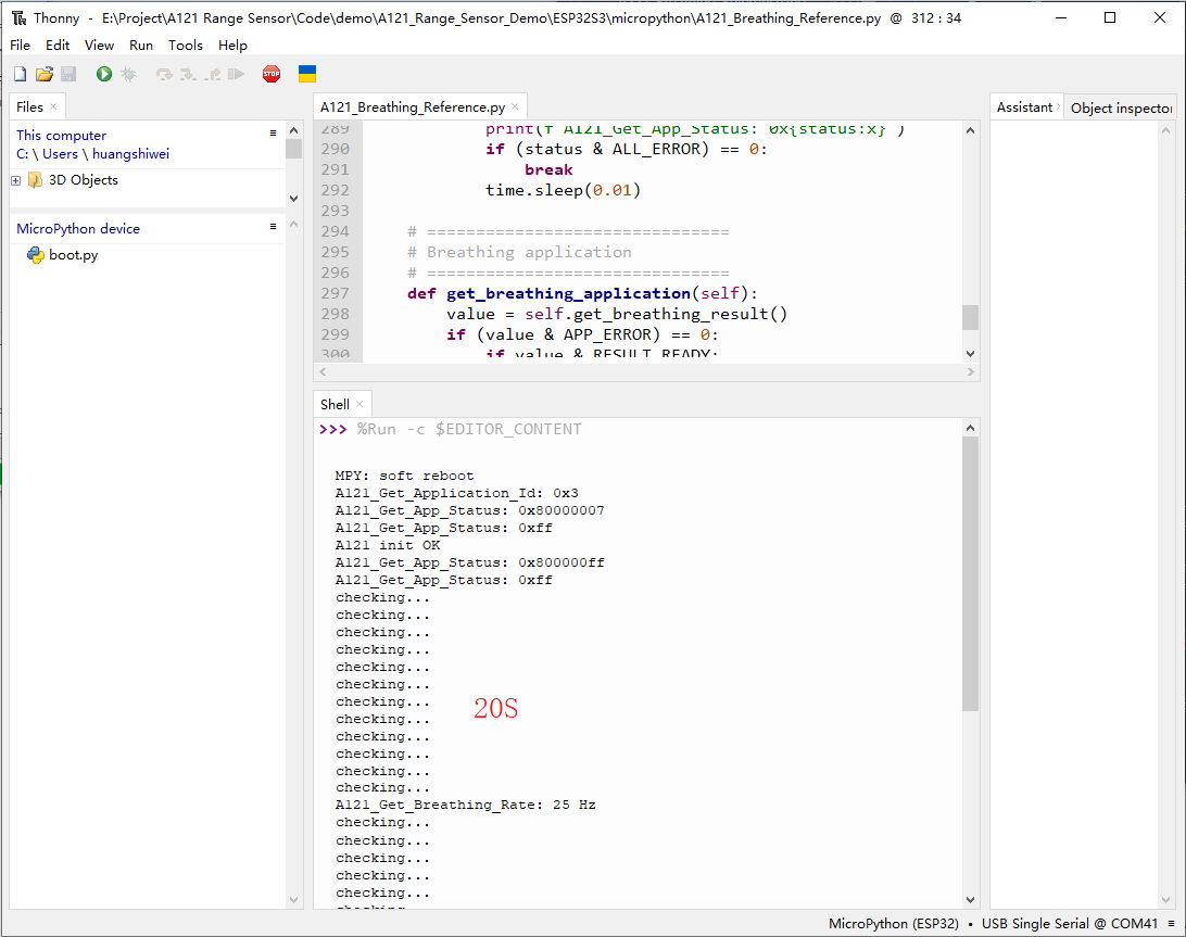
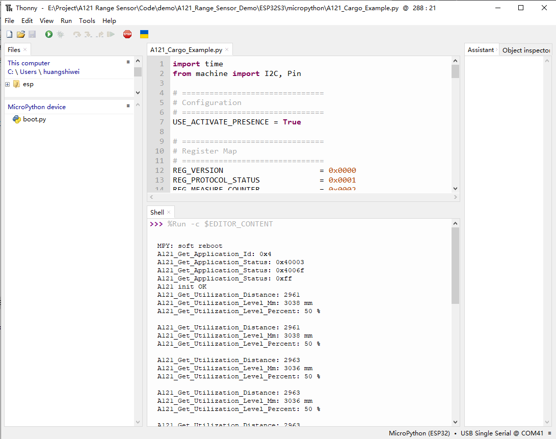
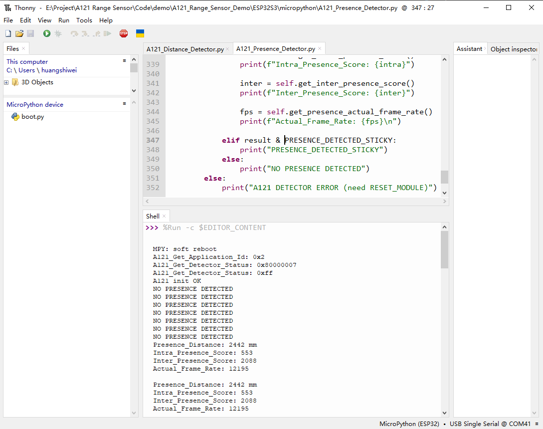
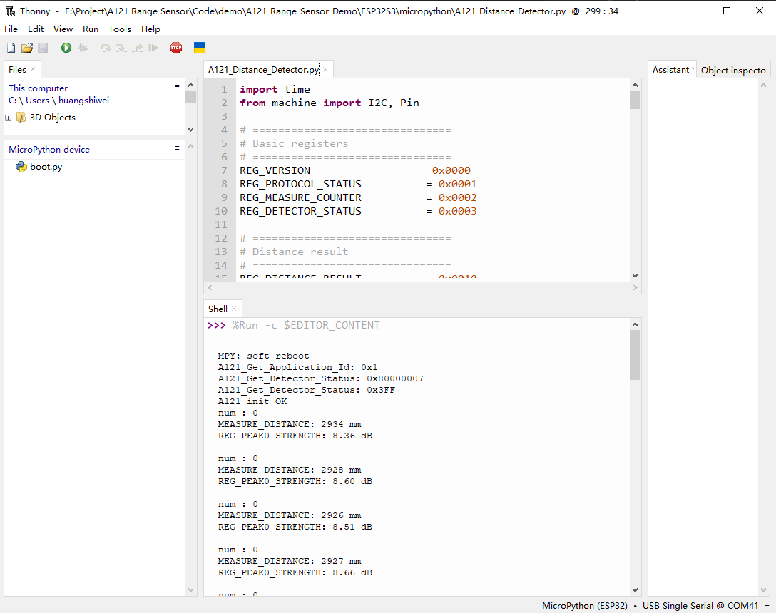
- The shell will output the relevant information, as shown below:
- BREATHING:
- CARGO:
- PRESENCE:
- DISTANCE:
Working with Pico
- For Pico environment setup and basic usage, please refer to this link.
- After setting up the environment, you can connect the sensor and download the Demo
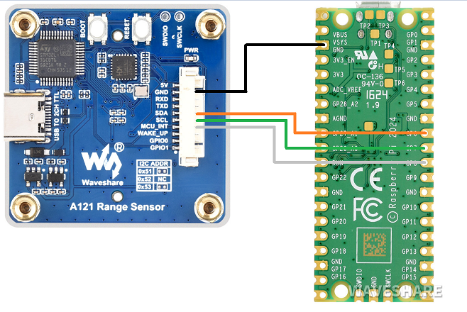
Hardware Connection
- Refer to the following diagram for connection:
Arduino Pico Demos
- Navigate to A121_Range_Sensor_Demo\pico\Arduino\*, where * is the demo corresponding to the firmware. Double-click the .ino file.
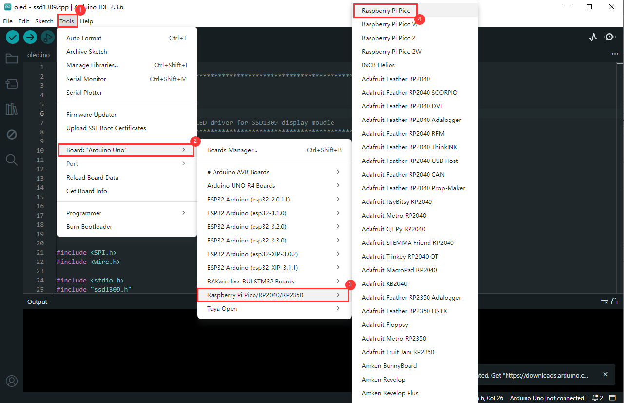
- Select development board:
- Select the port of the Pico, and then compile and upload it
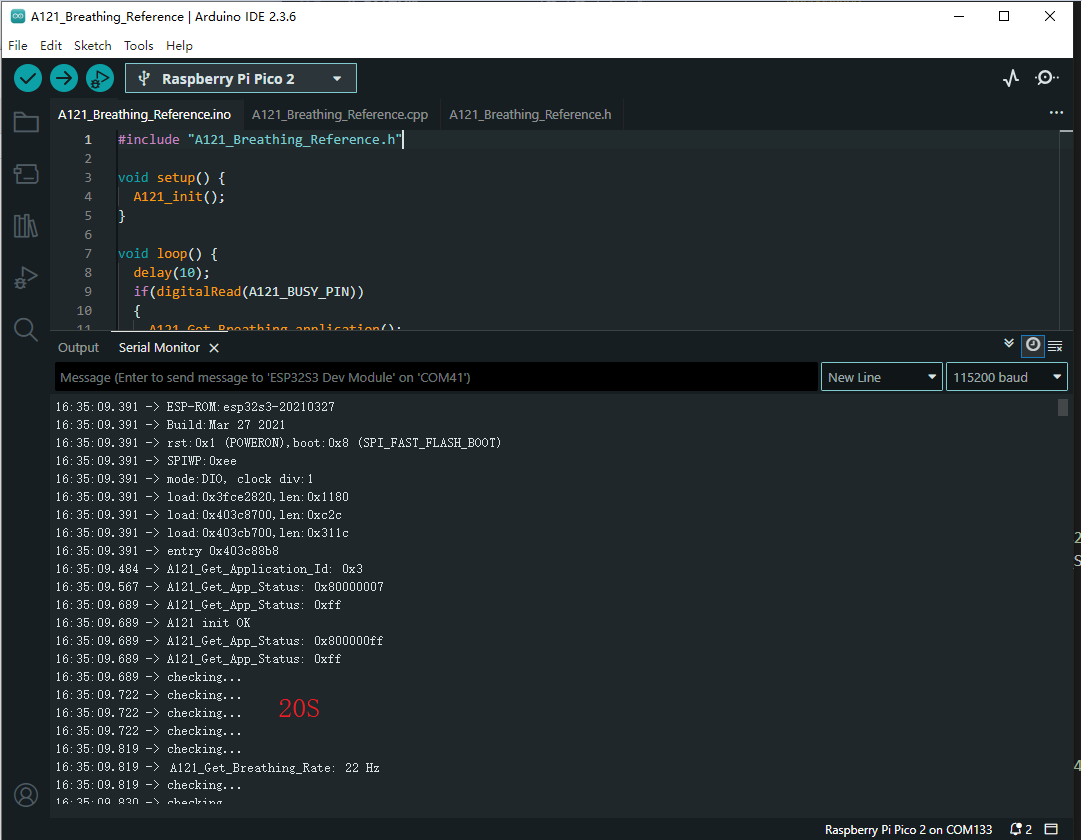
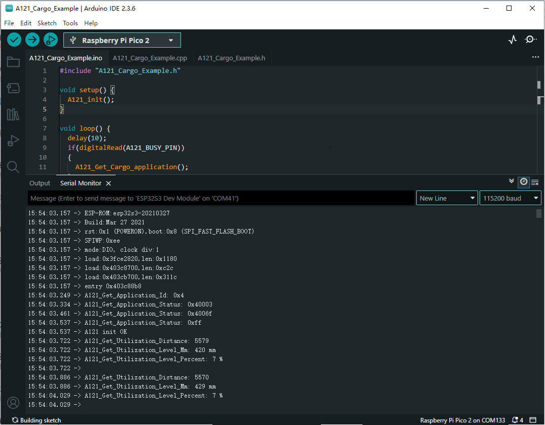
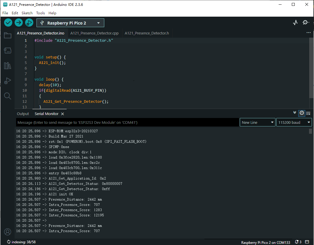
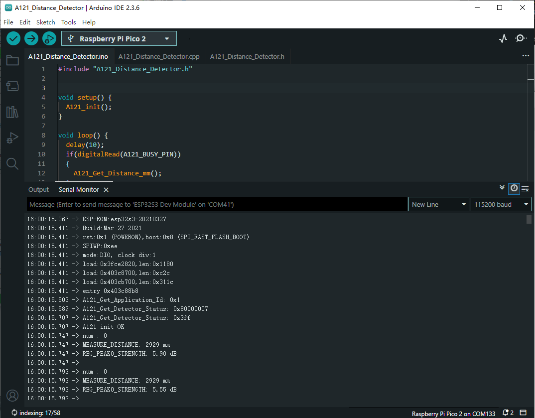
- After the upload is completed, open the serial port monitor, and the relevant information will be output, as shown below:
- BREATHING:
- CARGO:
- PRESENCE:
- DISTANCE:
Micropython Demos
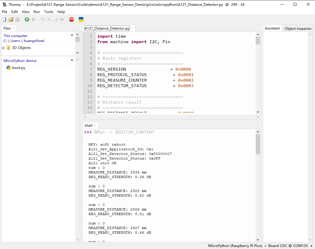
- Navigate to A121_Range_Sensor_Demo\pico\micropython. Double-click the .py file corresponding to the firmware.
- Select development board:
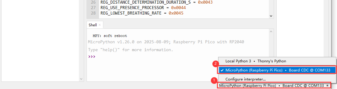
- Select the port of the ESP32S3, and then run the demo
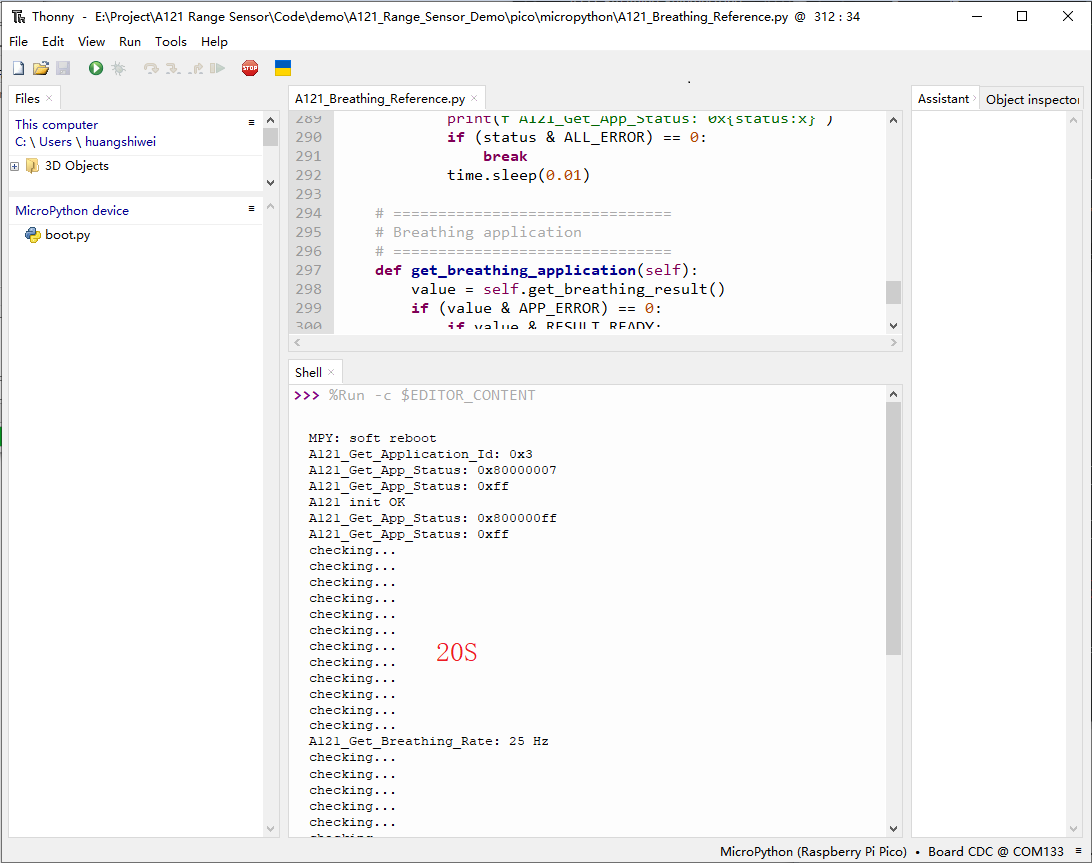
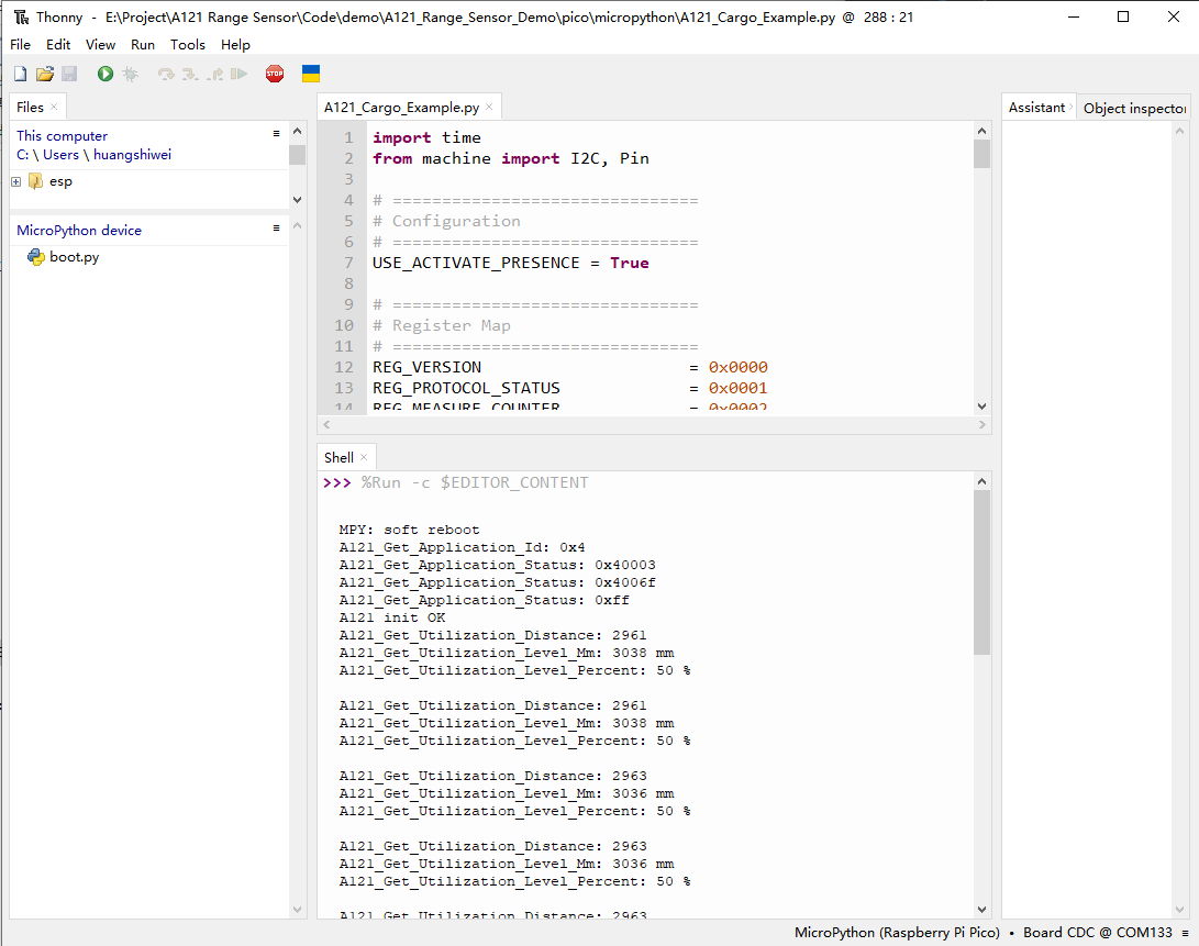
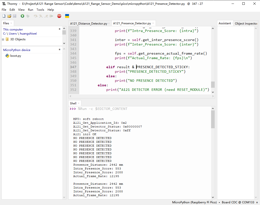
- The shell will output the relevant information, as shown below:
- BREATHING:
- CARGO:
- PRESENCE:
- DISTANCE:
Working with Arduino
- For Arduino environment setup and basic usage, please refer to this R4 link, R3 is installed by default.
- After setting up the environment, you can connect the sensor and download the Demo
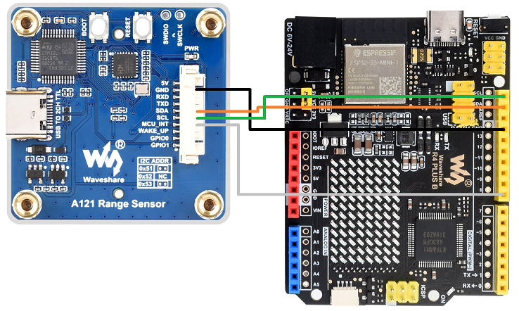
Hardware Connection
- Refer to the following diagram for connection:
Arduino Demos
- Navigate to A121_Range_Sensor_Demo\Arduino\*, where * is the demo corresponding to the firmware. Double-click the .ino file.
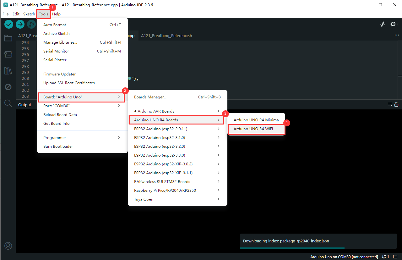
- Select development board:
- Select the port of the Pico, and then compile and upload it
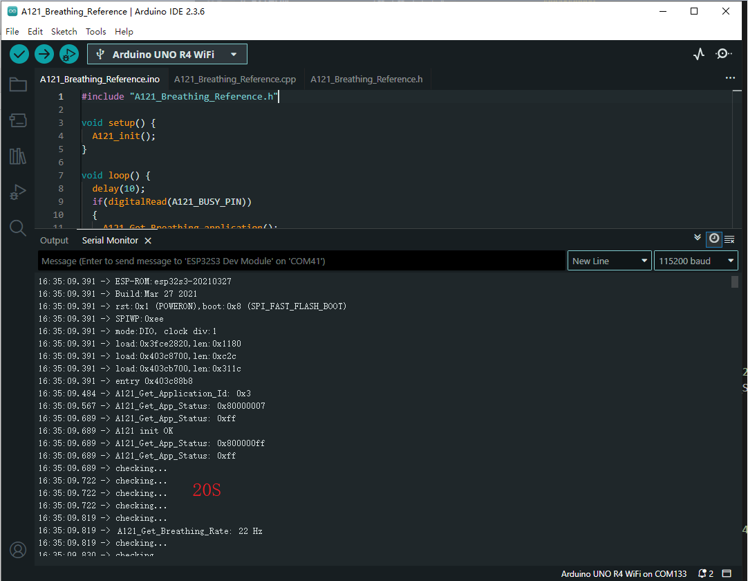
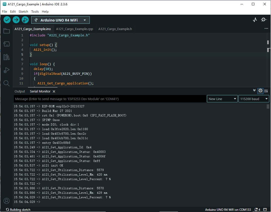
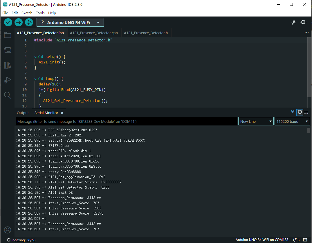
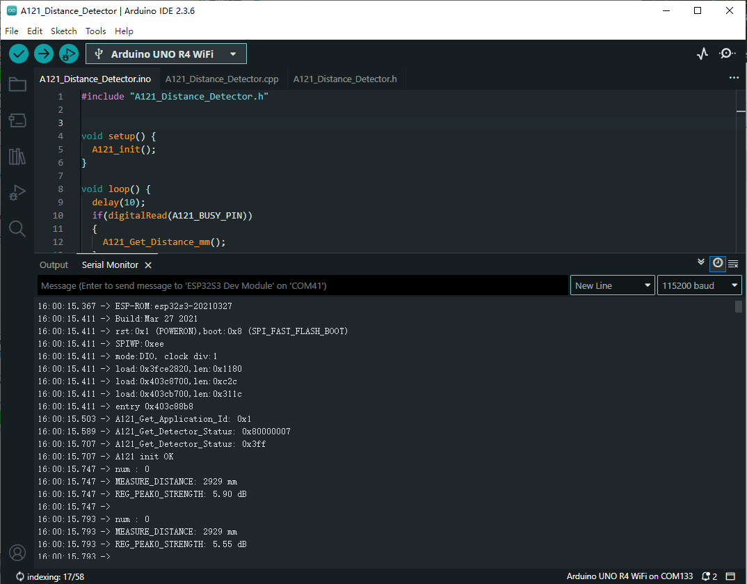
- After the upload is completed, open the serial port monitor, and the relevant information will be output, as shown below:
- BREATHING:
- CARGO:
- PRESENCE:
- DISTANCE:
Resources
schematic
Documents
Demo
Software
Related Resources
FAQ
Support
Monday-Friday (9:30-6:30) Saturday (9:30-5:30)
Email: services01@spotpear.com
[Tutorial Navigation]
- Overview
- Introduction
- Usage Scenarios
- Operating Principle
- Specifications
- Exploration Tool
- Firmware Description
- Lens Description
- Detection Range
- Other Information
- Dimensions
- UART Firmware Usage
- I2C Firmware Usage
- Resources
- FAQ
- Support