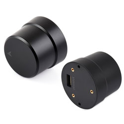
- sales/support
Google Chat:---
- sales
+86-0755-88291180
- sales01
sales@spotpear.com
- sales02
dragon_manager@163.com
- support
tech-support@spotpear.com
- CEO-Complaints
zhoujie@spotpear.com
- Only Tech-Support
WhatsApp:13246739196
- Purchase/Shipping/Refund
WhatsApp:13424403025
- HOME
- >
- ARTICLES
- >
- Common Moudle
- >
- GSM-GPS
Q43 NEO-F9P GNSS Helical RTK Module User Guide
Specifications
| Antenna Parameters | Frequency Bands | GPS: L1/L5 |
|---|---|---|
| Characteristic Impedance | 50Ω | |
| Polarization | RHCP (Right‑Hand Circular Polarization) | |
| Coverage | 360° | |
| Peak Gain | 2.5dBi | |
| VSWR | ≤ 2 | |
| Axial Ratio | ≤3dB | |
| Amplifier Parameters | Gain | 23dB |
| Noise Figure | 1.5dB | |
| Output VSWR | ≤ 2 | |
| System Parameters | Positioning Module | NEO-F9P-15B |
| Magnetometer | QMC5883P | |
| Operating Voltage | 3.3V - 16V | |
| Power Consumption | 500mW (Typ.) | |
| PVT Single‑Point Positioning Accuracy | Horizontal: 1.5m | |
| Vertical: 2.0m | ||
| SBAS Positioning Accuracy | Horizontal: 1.0m | |
| Vertical: 1.5m | ||
| RTK Accuracy | Horizontal: 1cm + 1ppm | |
| Vertical: 1cm + 1ppm | ||
| Time Accuracy (RMS) | 30ns | |
| Velocity Accuracy (RMS) | 0.05m/s | |
| Cold Start TTFF | <30s | |
| Initialization Time | <5s (typical) | |
| Initialization Reliability | > 99.9% | |
| Data Update Rate | 25Hz (Max) | |
| Data Format | RTCM 3.3; SPARTN 2.0.1 | |
| Other Parameters | Communication Interface | I2C, UART (9.6k - 921.6kbps def 38.4kbps) |
| Physical Interface | GH1.25 8PIN | |
| Operating Temperature Range | -40℃ - +85℃ | |
| Storage Temperature Range | ||
| Humidity | ≤ 95% | |
| Dimensions | 37.00 × Φ47.04 (mm) |
Pinout Definition
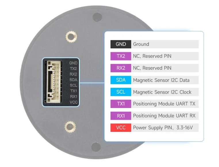
Dimensions
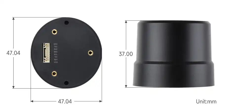
Working with Windows
This section covers quick setup and usage of the Q43 NEO‑F9P GNSS Helical RTK Module with software such as u‑center on a Windows PC. For detailed u‑center usage, refer to the u‑center User Guide.
Hardware Connection
- Connect the Q43 to a PC, Raspberry Pi, or Jetson Orin series board via a USB‑to‑UART module. This example uses a Windows PC for testing, with the default baud rate set to 38400 bps. The hardware connection is shown below:

- Download and install:
- Download the RTK Debug Tool (no installation required, source code included, supports secondary development)
RTK Rover Positioning
One Q43 NEO‑F9P GNSS Helical RTK Module acts as a rover connected to an RTK base station service for testing.
Open u‑center and select the COM port corresponding to the serial module:
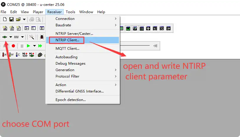
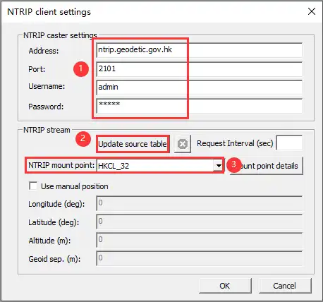
In the u‑center menu bar, click Receiver -> NTRIP, and enter the following parameters in the pop‑up tab:
Address: ntrip.geodetic.gov.hkPort: 2101Mount Point: HKCL_32Username: adminPassword: adminWARNINGUsers must first apply for a reference base station service available in their area. For example, users in the United States can apply to services such as UNAVCO. The author is located in Shenzhen and uses the Hong Kong Geodetic Survey Services as an example for testing. Reference station distance, network coverage, differential data quality, and local environmental conditions all affect positioning performance. Therefore, it is recommended to choose a suitable local base station or NTRIP service based on your actual location; commercial services such as Trimble, Hexagon, or Qianxun SI can also be used for a more stable experience.
After entering the parameters, click Update source table, select HKCL_32 from the NTRIP mount point dropdown, then click OK to save and start the RTK service:
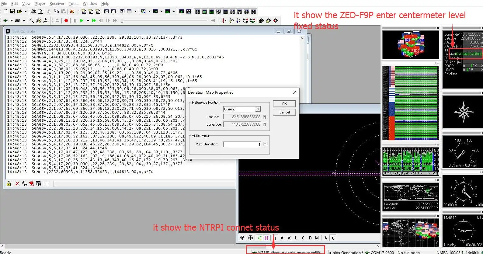
Once the NTRIP connection is successful, the connection status will be displayed at the bottom of u‑center:
RTK Base RTK Caster RTK Rover
Two Q43 NEO‑F9P GNSS Helical RTK Modules are used as the RTK base station and rover respectively.
Before setting up the base station module, first understand NTRIP (Networked Transport of RTCM via Internet) — a protocol that distributes RTK correction data over the Internet or a local network. NTRIP supports multi‑base and multi‑rover RTK networks. A network with multiple NTRIP devices is called an NTRIP network.
An NTRIP network has three roles: the NTRIP Caster is a server that receives and sends GNSS differential data. It collects RTK correction data (i.e., RTCM data) from one or more base stations and distributes it to RTK rovers. Emlid Caster and rtk2go are cloud‑based public Casters that allow you to upload RTCM data to these relay stations, avoiding the need to set up your own Caster.
Configuring Base Station Mode and Outputting RTCM via UART1
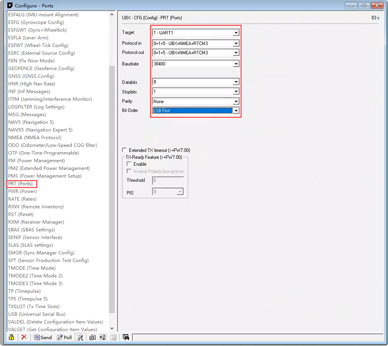
Open View -> Configuration View -> PRT and set the following:
Target: 1 - UART1Protocol in: UBX + NMEA + RTCM3Protocol out: UBX + NMEA + RTCM3Baudrate: 38400Databits: 8Stopbits: 1Parity: NoneClick Send to confirm the configuration.
Next, select the MSG (Messages) option, then select and set each of the following to output on UART1:
RTCM3.3 1005RTCM3.3 1074RTCM3.3 1077RTCM3.3 1084RTCM3.3 1087RTCM3.3 1094RTCM3.3 1097RTCM3.3 1124RTCM3.3 1127RTCM3.3 1230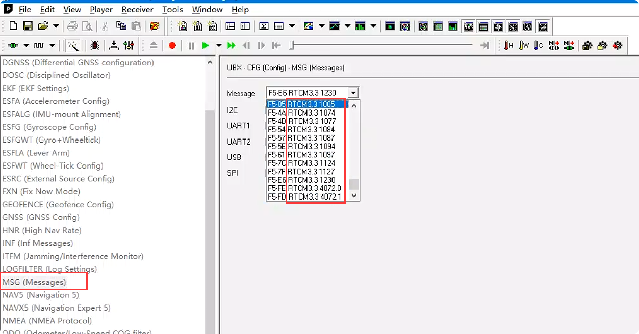
Then go to View -> Configuration View -> TMODE3 and select:
Mode: Survey-inMinimum observation time: 120 sRequired position accuracy: 30 m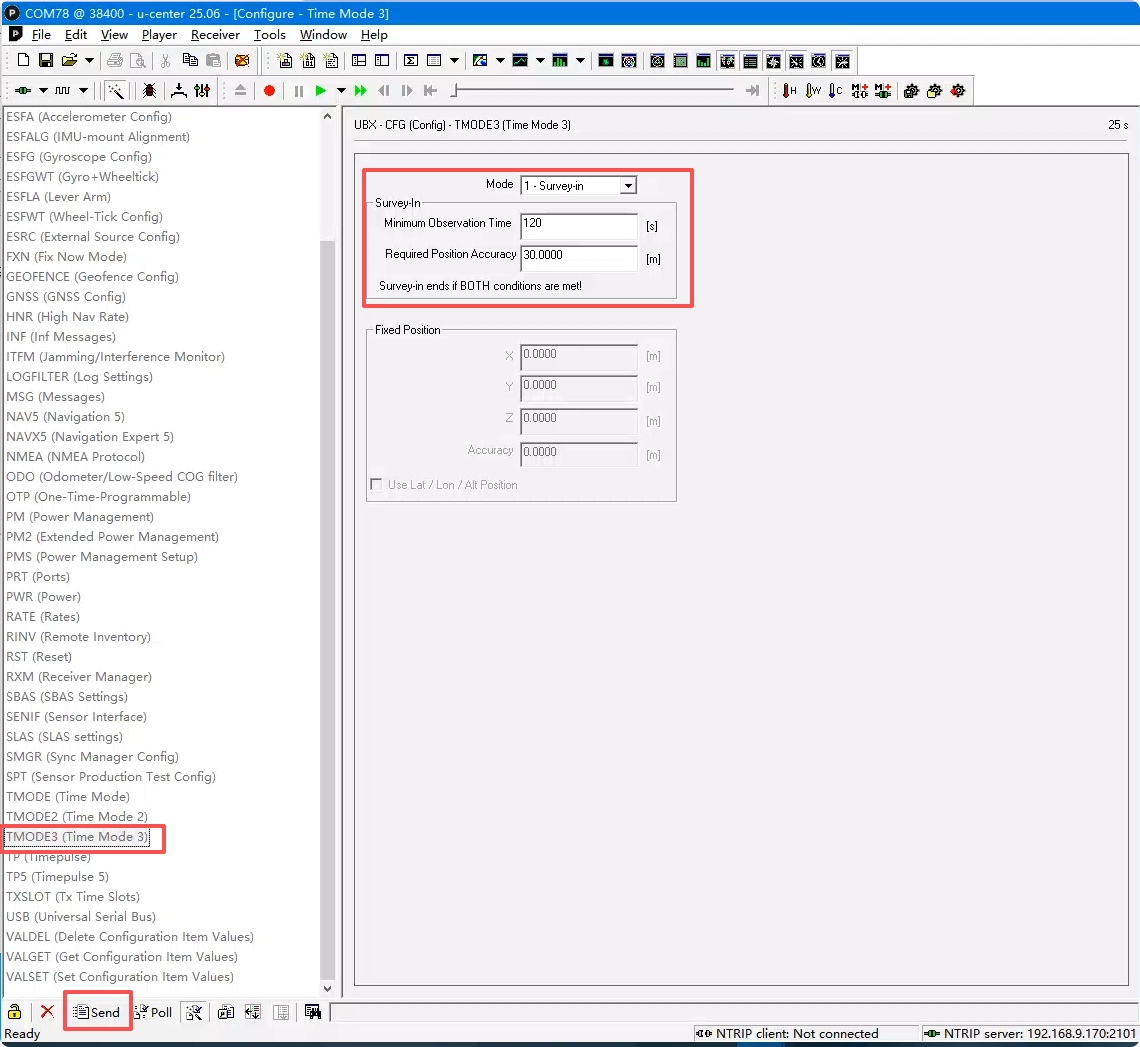 WARNING
When the Q43 operates as a base station, the convergence time is relatively long. It is recommended to let the base station run for 12 hours and use the converged position as the base station position. The antenna should be installed at a fixed point with a clear, unobstructed view of the sky.
Configure the Caster Service
The following example uses the Emlid Caster public Caster for testing:
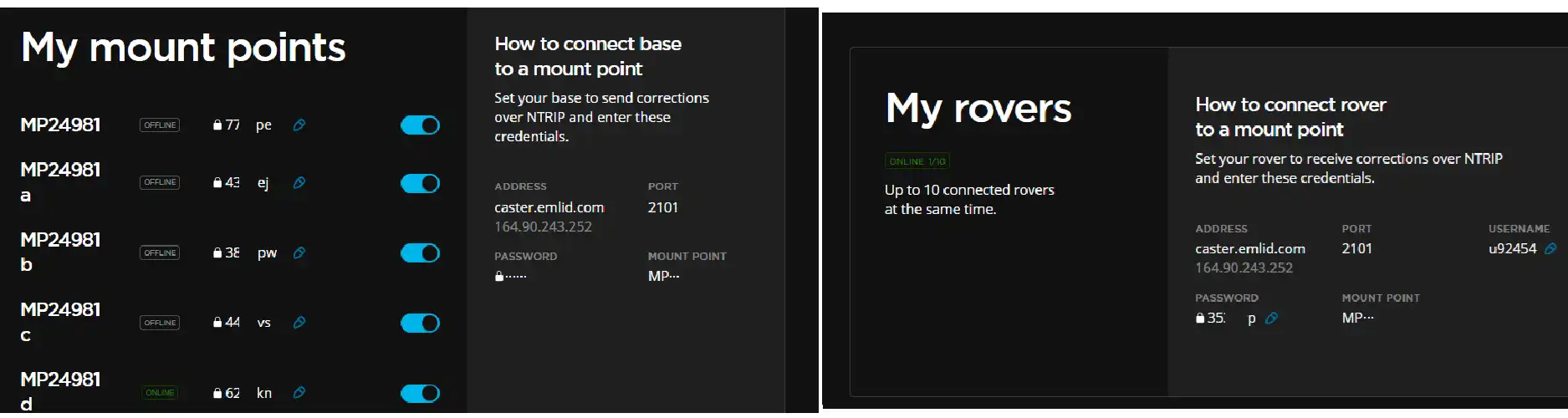
Register and log in to Emlid Caster to obtain an NTRIP mount point.
Assign the My mount points configuration shown below to the base station, and the My rovers parameters to the rover, using the same mount point.
 WARNING
Emlid Caster is for testing hardware functionality only. For production use, we recommend setting up your own server to ensure stability.
Rover RTK Positioning
u‑center is not suitable for public‑network RTK Caster services. Use the RTK Debug Tool to transmit base station data to the rover. The RTK Debug Tool is developed based on the NEO‑F9P command manual and supports fast configuration of base station mode, NTRIP Client, NTRIP Caster, and NTRIP Server. You can also develop your own tools better suited to field applications.
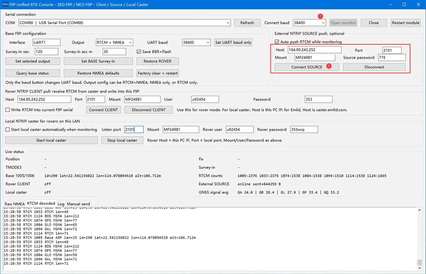
Open RTK Debug Tool window 1, select the COM port corresponding to the base station's serial module, and configure the following parameters:
Connect baud: 38400Host: 164.90.243.252Port: 2101Mount: MP24981Source password: 776XXXClick Connect SOURCE to upload base station data to the server.
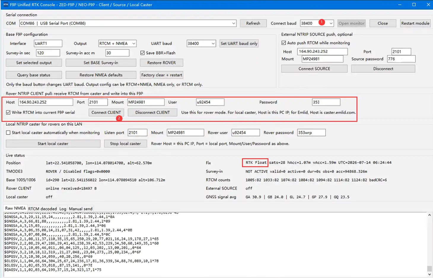
Open another RTK Debug Tool window 2, select the COM port corresponding to the rover's serial module, and configure the following parameters:
Connect baud: 38400Host: 164.90.243.252Port: 2101Mount: MP24981User: u92454Password: 353xxxClick Connect CLIENT. Once RTK Float appears, RTK positioning is achieved.
Working with ESP32
Connect the Q43 NEO‑F9P GNSS Helical RTK Module to the ESP32 via UART. Also attach the antenna and place the setup in an open outdoor area, or at least position the GNSS antenna with a clear view of the sky. The pin connections are shown in the table below:
ESP32-S3 Q43 NEO-F9P GNSS Helical RTK Module GND GND GPIO17 SDA GPIO18 SCL GPIO9 TX1 GPIO8 RX1 3V3/5V VCC This guide uses the ESP32-S3 for testing. Set up the ESP32-S3 environment, and modify the following parameters in the example code.
//Connect ESP to WiFi to enable access to base station server dataconst char* ssid = "mate60"; // Wi‑Fi SSIDconst char* wifiPassword = "131433"; // Wi‑Fi password// ---------- NTRIP (using Hi‑Target CORS as an example; modify accordingly) ----------const char* ntripHost = "120.253.226.97";const int ntripPort = 8001;const char* mountpoint = "RTCM33_GRCEJ";const char* ntripUser = "cvmh11286";const char* ntripPass = "fyxxx";Download the example. Locate
GetGPS-RTK.inoin theQ43_NEO-F9P_GNSS_Helical_RTK_Module/ESP32/GetGPS-RTKfolder, compile and flash the program to the ESP32-S3. The RTK rover positioning test result is shown in the figure below: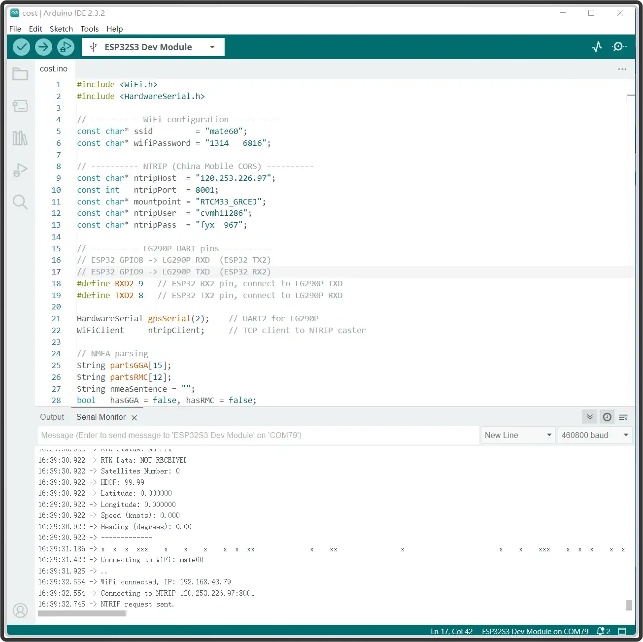
Running the
QMC5883P.inoexample provides the magnetic field intensity along the X, Y, and Z axes in the environment, as shown below: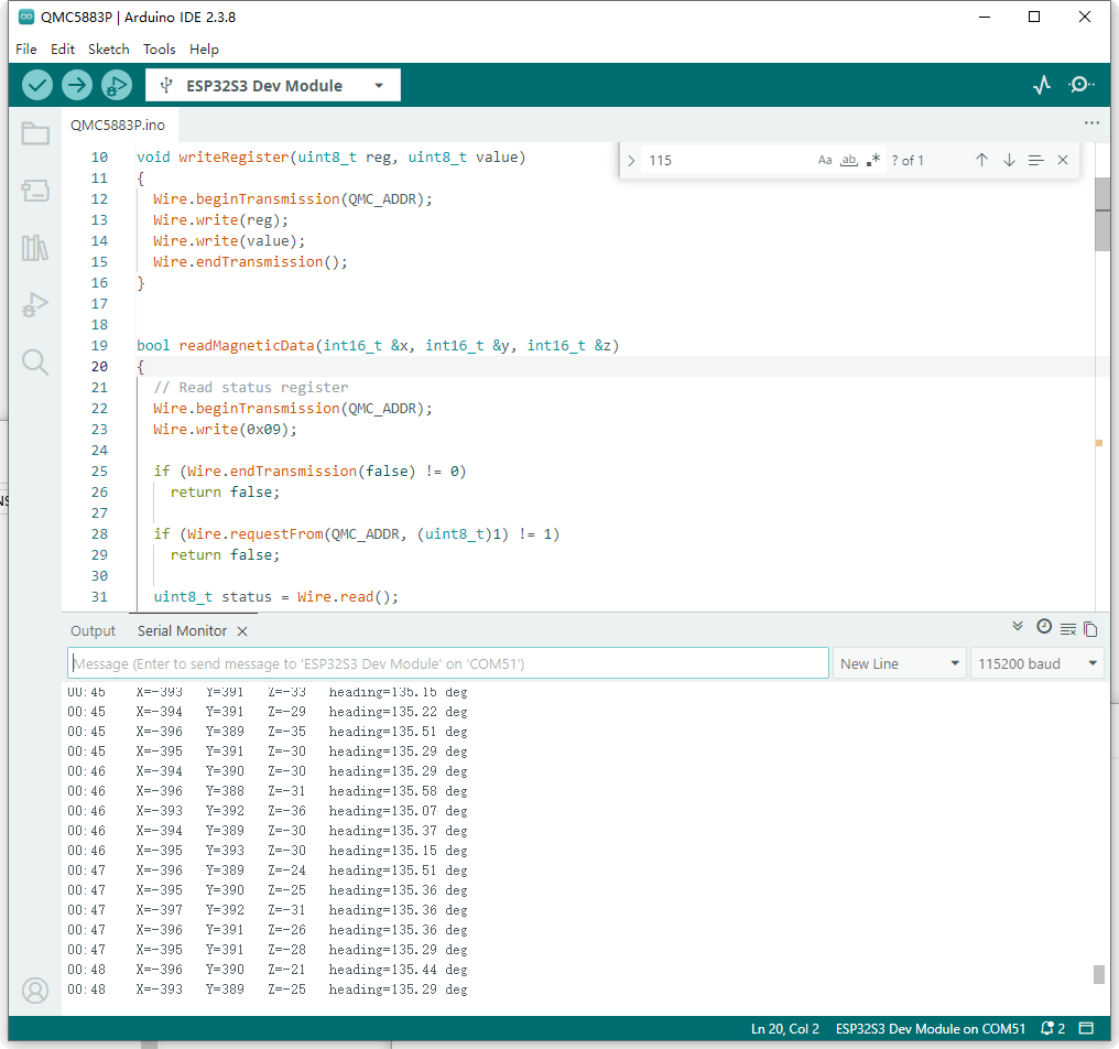
Working with Raspberry Pi
This section demonstrates using Raspberry Pi + 2 Q43 modules for testing: one set to Base Station mode, the other set to Rover mode, while also testing the geomagnetic sensor for an electronic compass application. The overall Linux system operations are similar and can also be adapted to common Linux mainboards like Jetson and RDK. It is recommended to test in an open, clear ☀, outdoor environment with a clear view of the sky: the more open and better the weather ☀, the more stable and accurate the RTK positioning.
Environment Configuration
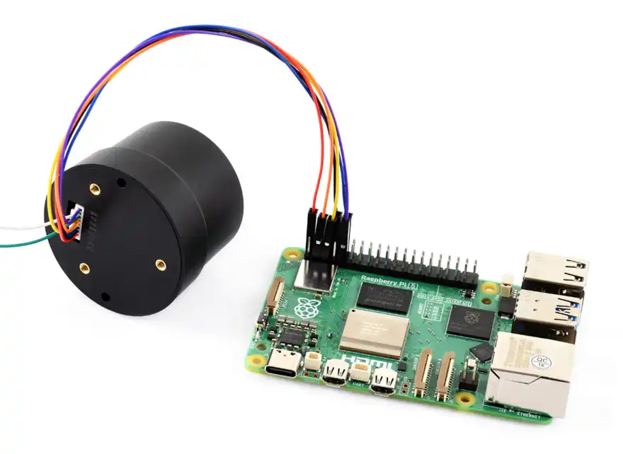
Connect the Q43 module to the Raspberry Pi's UART0 and I2C1 pins using a GH1.25 cable. The UART connects to the RTK positioning module, and I2C connects to the QMC5883P geomagnetic sensor. The hardware connection is shown in the figure below:
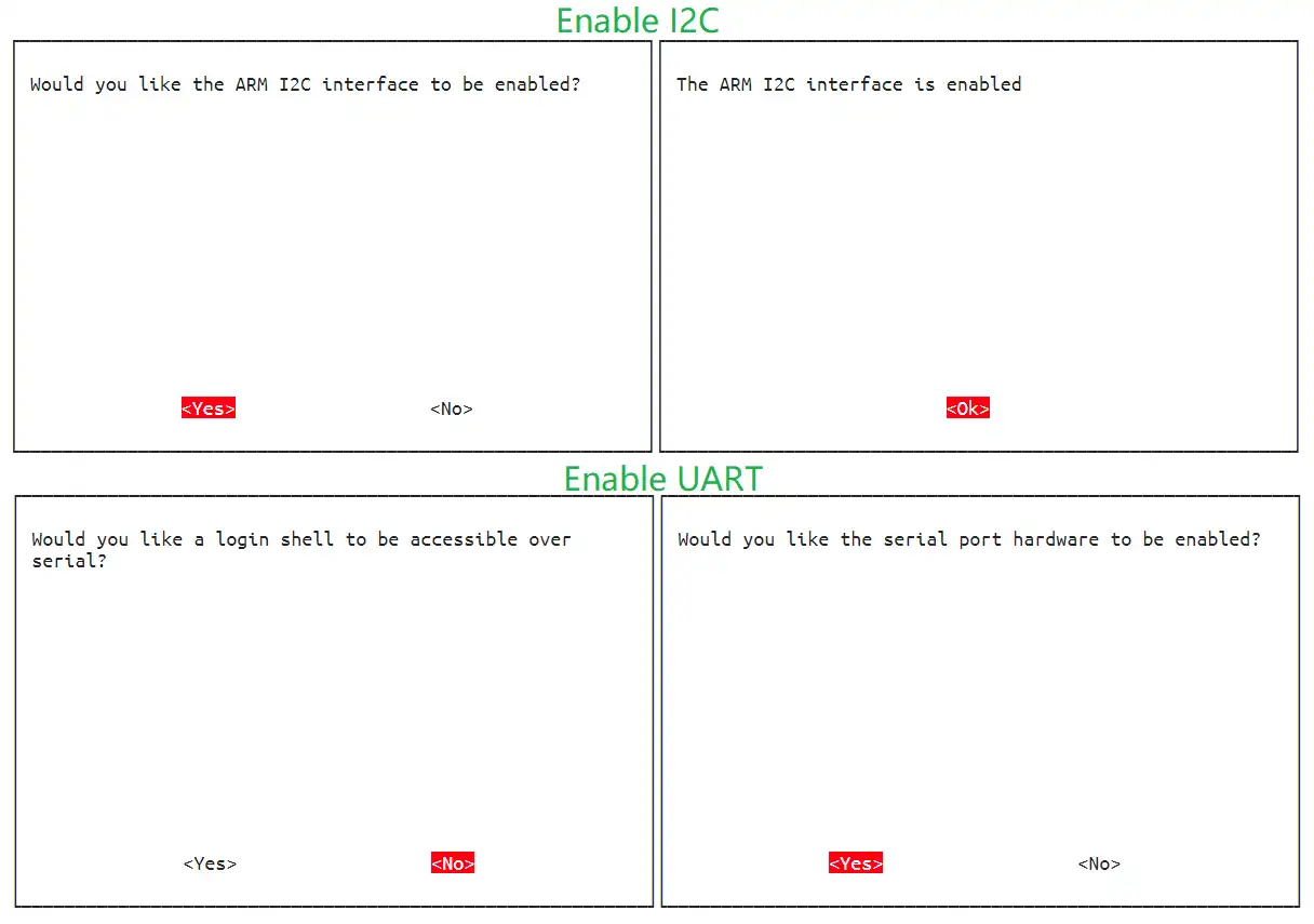
Enable the Raspberry Pi's I2C and UART interfaces: In the UART settings, first select NO to turn off the shell debug serial port, then select YES to open the UART serial port, as shown below:
RTK Base
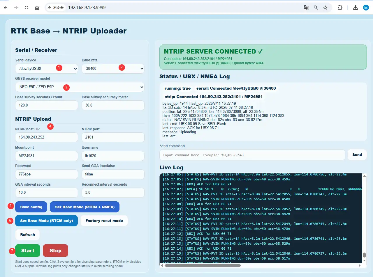
Download and run the Python 3 program in the Raspberry Pi terminal; then enter the IP + port number generated by the program in a browser to open the NTRIP Server web interface. The default configuration is 115200 baud rate, serial port ttyAMA0, and pre-configured parameters for Caster Emlid. You can customize them according to the actual situation:
pip3 install flask pyserial
wget https://files.waveshare.com/wiki/Q43_NEO-F9P_GNSS_Helical_RTK_Module/Demo/Q43_NEO-F9P_GNSS_Helical_RTK_Module.zip
sudo unzip Q43_NEO-F9P_GNSS_Helical_RTK_Module.zip
cd Q43-GNSS-Helical-RTK-Module/Raspberry-Pi/
sudo python3 Base-RTK.py
RTK Rover
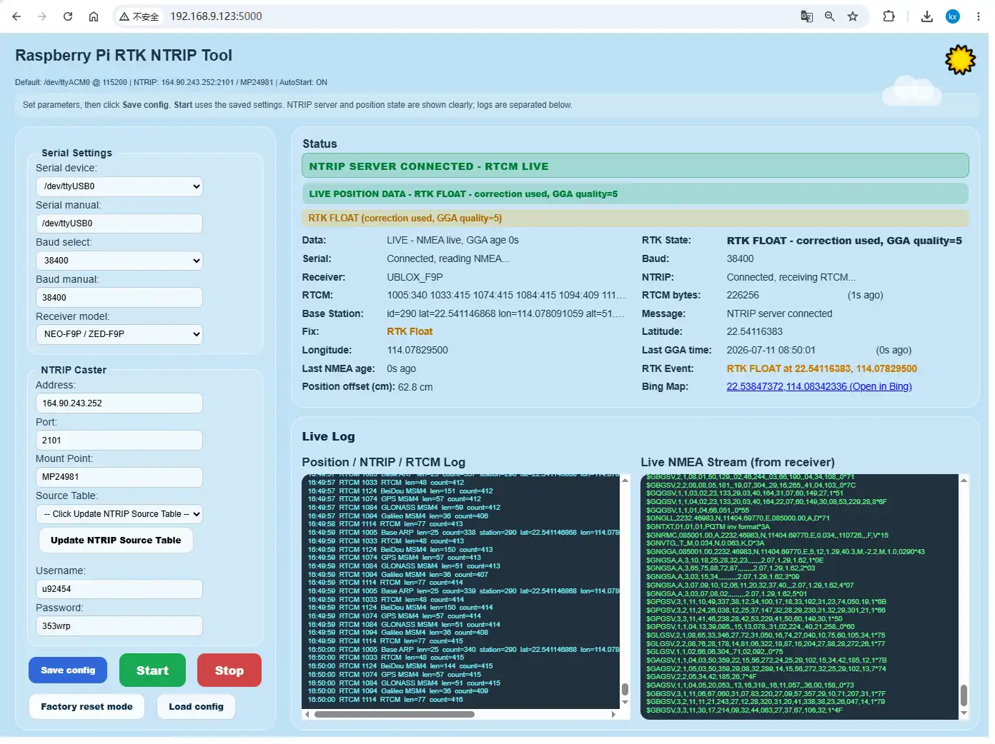
Open a new terminal on the Raspberry Pi and run the Python 3 program; then enter the IP + port number generated by the program in a browser to open the NTRIP Client web interface. Please fill in the parameters according to the actual Caster to achieve RTK precise positioning:
sudo python3 Rover-RTK.py
Electronic Compass
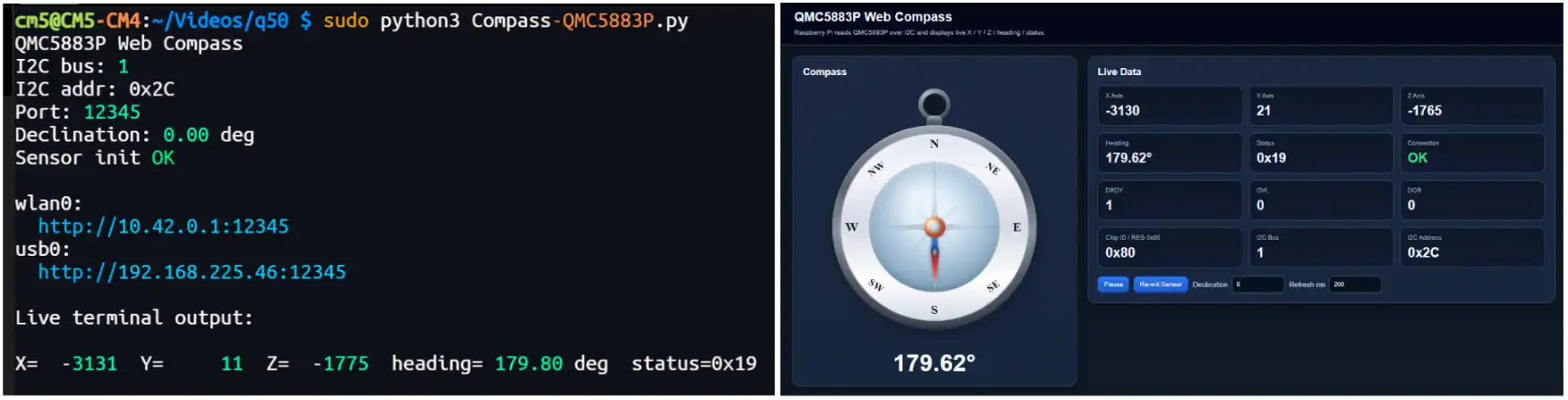
The module has an onboard QMC5883P geomagnetic sensor, which can be driven via I2C to implement an electronic compass application. Run the following programs on the Raspberry Pi:
sudo python3 Compass-QMC5883P.py
After running the program, you can obtain the environmental magnetic field strength and experience an electronic compass-like functionality:
Working with Raspberry Pi Pico
If RTK functionality is needed, please use the Raspberry Pi Pico 2 W series and follow steps similar to those for the ESP32 to achieve RTK positioning. This section uses the Raspberry Pi Pico 2 as an example for basic GNSS positioning. The connection table is as follows:
Raspberry Pi Pico 2 Q43 NEO-F9P GNSS Helical RTK Module GND GND GP2 SDA GP3 SCL GP1 TX1 GP0 RX1 VBUS VCC Open and run the
GetGPS.pyexample in Thonny to obtain raw GNSS messages, as shown in the figure below: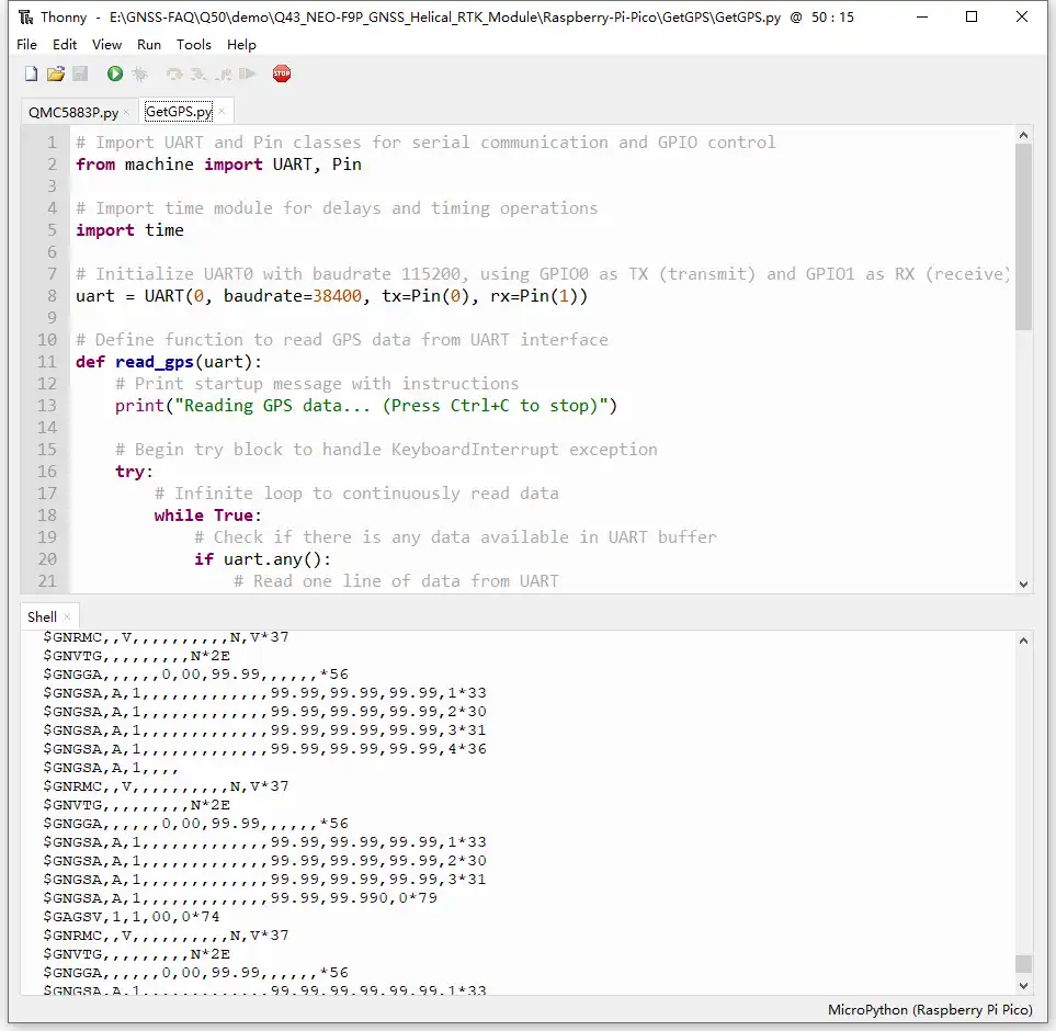
Run the
QMC5883P.pyexample to measure the ambient magnetic field strength, as shown in the figure below: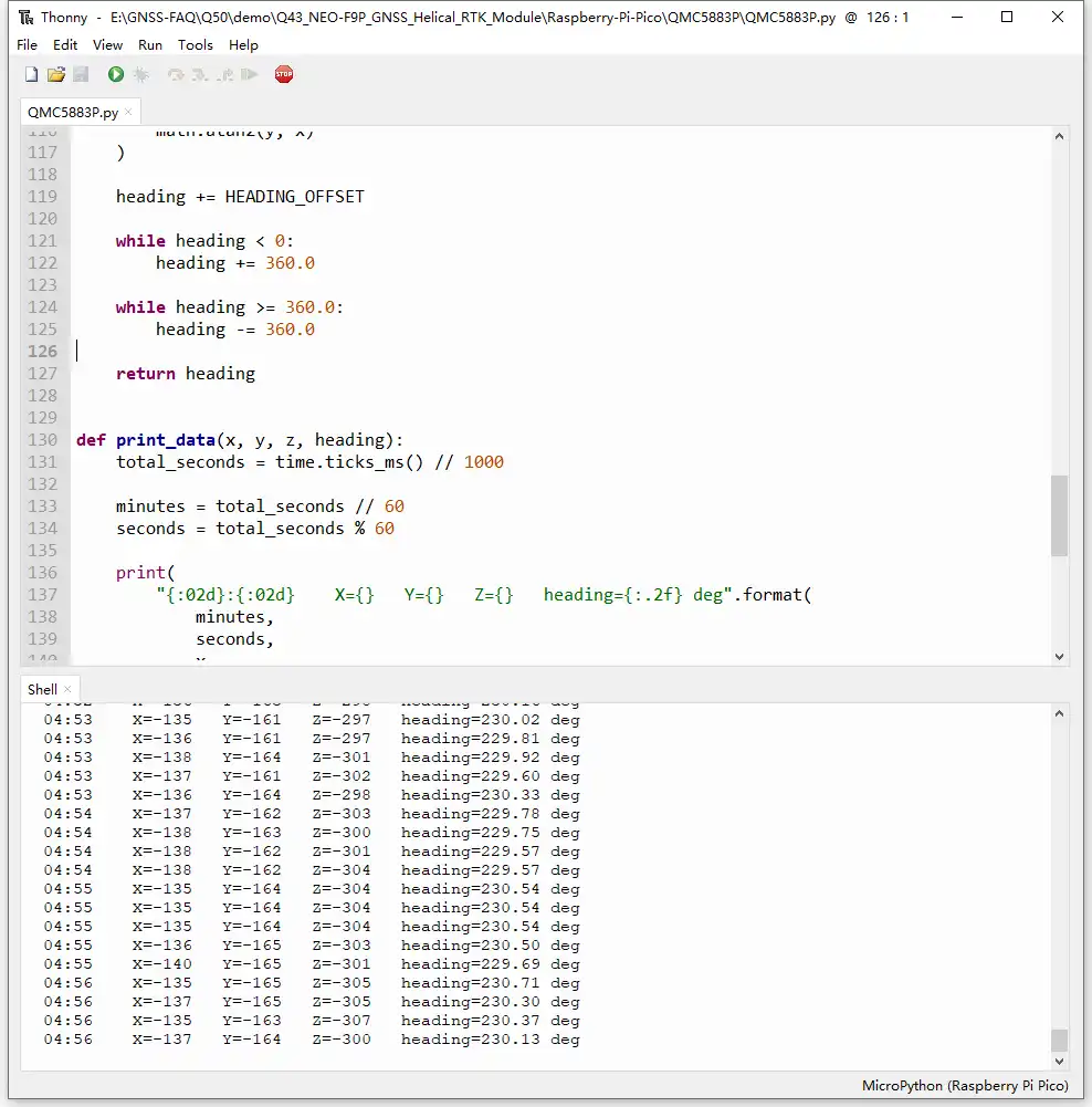
Resources
1. Hardware Resources
Development Board Design Files
2. Technical Manuals
3. Example
4. Drivers and Tools
Support
Monday-Friday (9:30-6:30) Saturday (9:30-5:30)
Email: services01@spotpear.com