


- sales/support
Google Chat:---
- sales
+86-0755-88291180
- sales01
sales@spotpear.com
- sales02
dragon_manager@163.com
- support
tech-support@spotpear.com
- CEO-Complaints
zhoujie@spotpear.com
- Only Tech-Support
WhatsApp:13246739196
- Purchase/Shipping/Refund
WhatsApp:13424403025
RP2350-Touch-LCD-1.69 User Guide
Overview
Introduction
RP2350-Touch-LCD-1.69 is a low-cost, high-performance MCU board designed by Waveshare. It is equipped with a 1.69inch capacitive touch LCD screen, a lithium battery charging chip, a six-axis sensor (three-axis accelerometer and three-axis gyroscope), RTC, buzzer and other peripherals, which are convenient for development and embedding into the product.
Features
- RP2350 microcontroller chip designed by Raspberry Pi
- Adopts unique dual-core and dual-architecture design, equipped with dual-core ARM Cortex-M33 processor and dual-core Hazard3 RISC-V core processor, flexible clock running up to 150 MHz
- Built-in 520KB of SRAM and 16MB of on-chip Flash
- Type-C connector, keeps it up to date, easier to use
- Onboard 1.69inch capacitive touch LCD display, 240×280 resolution, 262K color
- Onboard Lithium battery recharge/discharge header, suitable for mobile devices
- Onboard RTC clock chip and RTC battery header for timing and scheduling functions
- Onboard buzzer for sound-producing peripheral
- USB1.1 host and device support
- Low-power sleep and dormant modes
- Drag-and-drop programming using mass storage over USB
- Temperature sensor
- Accurate clock and timer on-chip
- On-chip accelerated floating-point library
Specifications
| LCD parameters | |||
| Touch Chip | CST816T | Touch Port | I2C |
| Display Chip | ST7789V2 | Display Interface | SPI |
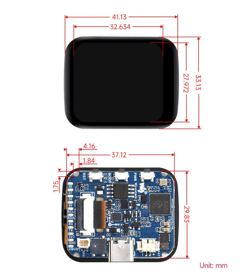
| Resolution | 240(H)RGB x 280(V) | Display Size | 27.972mm × 32.634mm |
| Display Panel | IPS | Pixel Pitch | 0.11655mm × 0.11655mm |
| IMU parameters | |||
| Sensor Name | QMI8658 | ||
| Accelerometer characteristics | Resolution: 16 bits Measuring Range (optional): ±2, ±4, ±8, ±16g | ||
| Gyroscope characteristics | Resolution: 16 bits Measuring Range (optional): ±16, ±32, ±64, ±128, ±256, ±512, ±1024, ±2048°/sec | ||
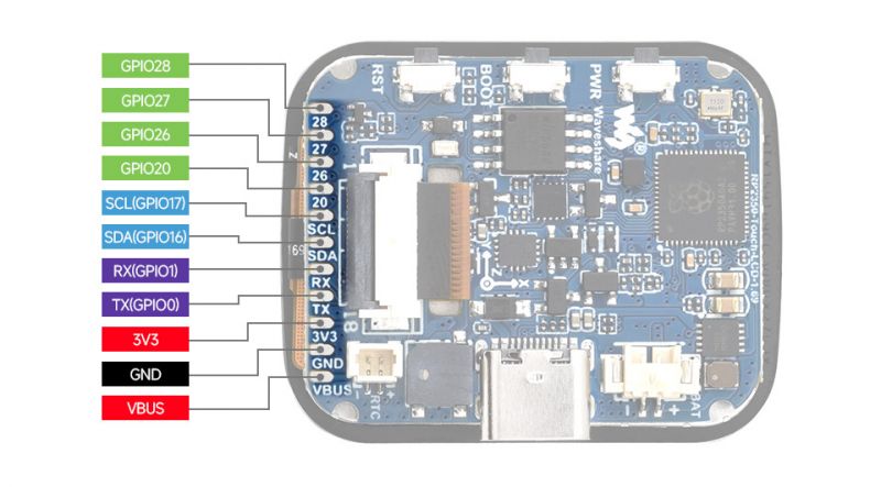
Pinout Definition
Dimensions
Pico Getting Started
Firmware Download
- MicroPython Firmware Download

- C_Blink Firmware Download

Basic Introduction
MicroPython Series
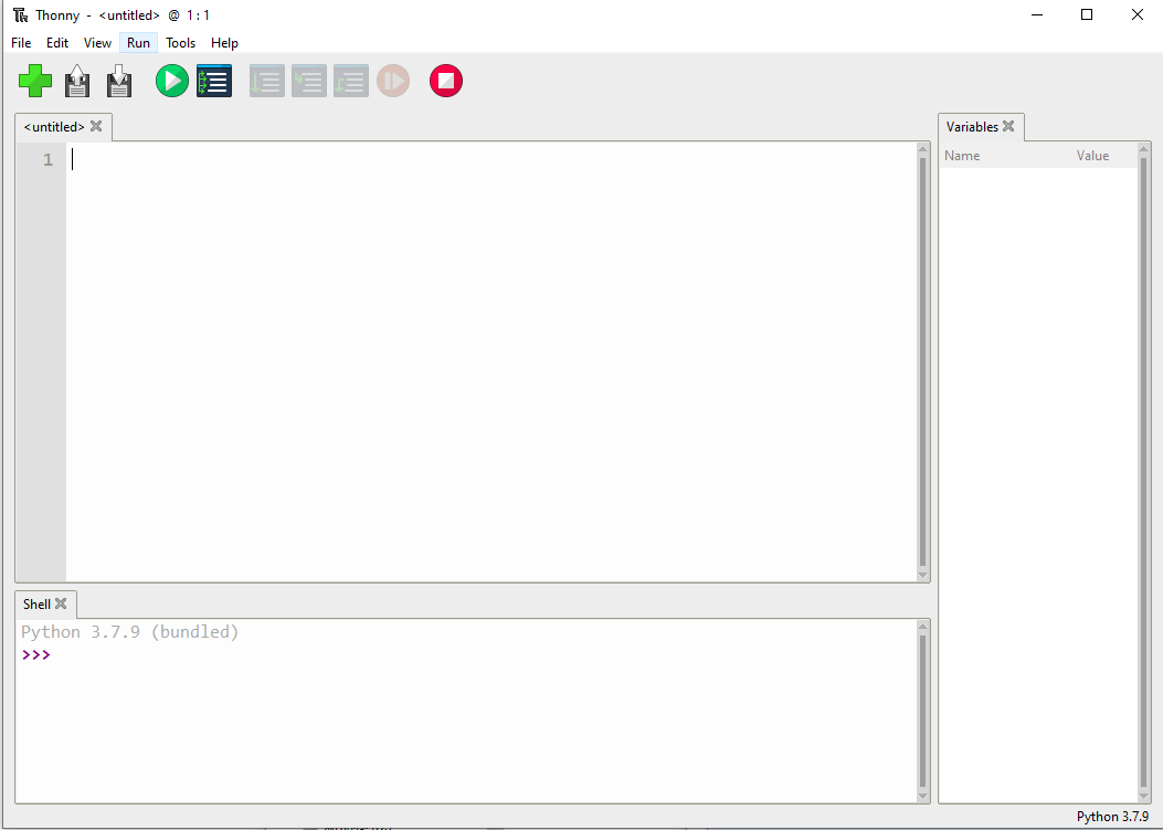
Install Thonny IDE
In order to facilitate the development of Pico/Pico2 boards using MicroPython on a computer, it is recommended to download the Thonny IDE
- Download Thonny IDE and follow the steps to install, the installation packages are all Windows versions, please refer to Thonny's official website for other versions
- After installation, the language and motherboard environment need to be configured for the first use. Since we are using Pico/Pico2, pay attention to selecting the Raspberry Pi option for the motherboard environment
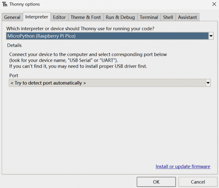
- Configure MicroPython environment and choose Pico/Pico2 port
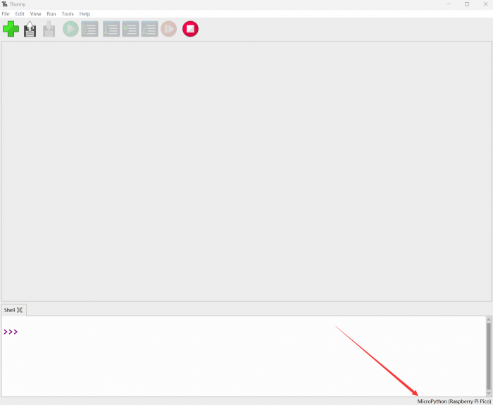
- Connect Pico/Pico2 to your computer first, and in the lower right corner of Thonny left-click on the configuration environment option --> select Configture interpreter
- In the pop-up window, select MicroPython (Raspberry Pi Pico), and choose the corresponding port

Flash Firmware
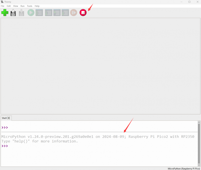
- Click OK to return to the Thonny main interface, download the corresponding firmware library and burn it to the device, and then click the Stop button to display the current environment in the Shell window
- Note: Flashing the Pico2 firmware provided by Micropython may cause the device to be unrecognized, please use the firmware below or in the package
- How to download the firmware library for Pico/Pico2 in windows: After holding down the BOOT button and connecting to the computer, release the BOOT button, a removable disk will appear on the computer, copy the firmware library into it
- How to download the firmware library for RP2040/RP2350 in windows: After connecting to the computer, press the BOOT key and the RESET key at the same time, release the RESET key first and then release the BOOT key, a removable disk will appear on the computer, copy the firmware library into it (you can also use the Pico/Pico2 method)
MicroPython Series Tutorials
【MicroPython】 machine.Pin class function details
【MicroPython】machine.PWM class function details
【MicroPython】machine.ADC class function details
【MicroPython】machine.UART class function details
【MicroPython】machine.I2C class function details
【MicroPython】machine.SPI class function details
【MicroPython】rp2.StateMachine class function details
C/C++ Series
For C/C++, it is recommended to use Pico VS Code for development. This is a Microsoft Visual Studio Code extension designed to make it easier for you to create, develop, and debug projects for the Raspberry Pi Pico series development boards. No matter if you are a beginner or an experienced professional, this tool can assist you in developing Pico with confidence and ease. Here's how to install and use the extension.
- Official website tutorial: https://www.raspberrypi.com/news/pico-vscode-extension/
- This tutorial is suitable for Raspberry Pi Pico, Pico2 and the RP2040 and RP2350 series development boards developed by Waveshare
- The development environment defaults to Windows11. For other environments, please refer to the official tutorial for installation
Install VSCode
- First, click to download pico-vscode package, unzip and open the package, double-click to install VSCode
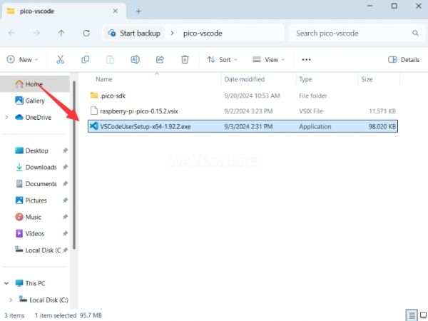
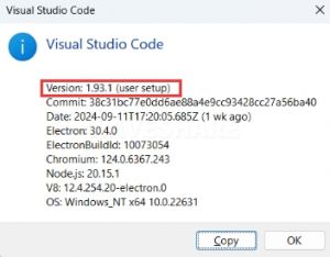
Note: If vscode is installed, check if the version is v1.87.0 or later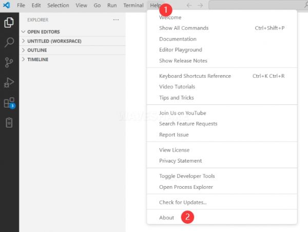
Install Extension
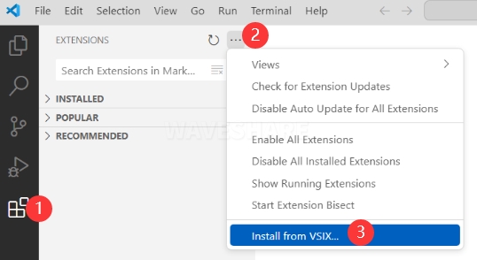
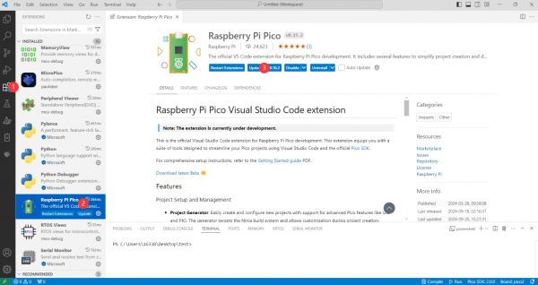
- Click Extensions and select Install from VSIX
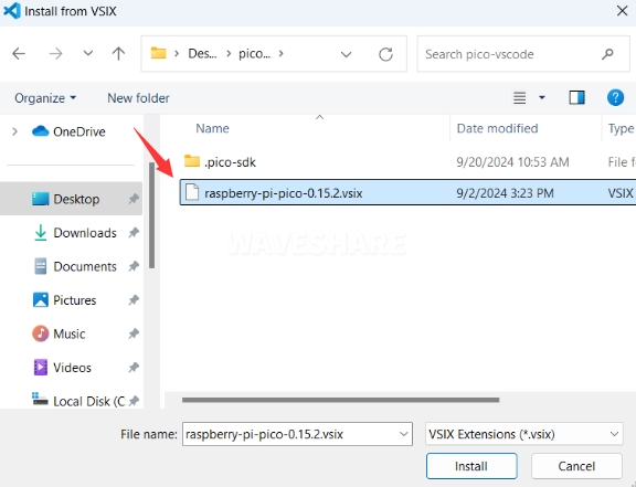
- Select the package with the vsix suffix and click Install
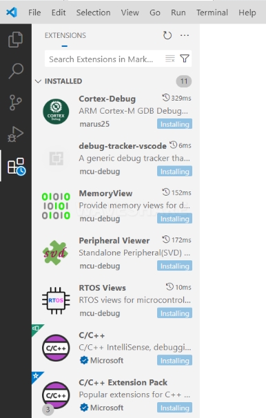
- Then vscode will automatically install raspberry-pi-pico and its dependency extensions, you can click Refresh to check the installation progress
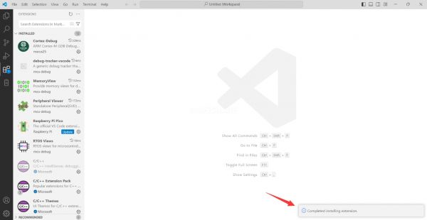
- The text in the right lower corner shows that the installation is complete. Close VSCode
Configure Extension
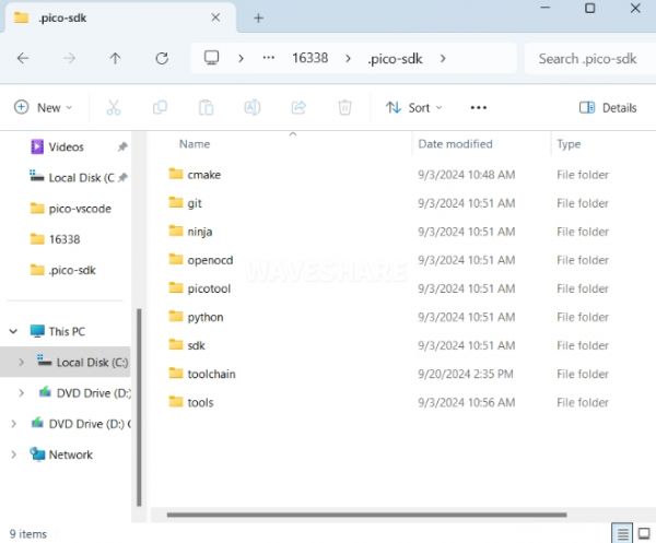
- Open directory C:\Users\username and copy the entire .pico-sdk to that directory
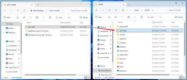
- The Copy is completed
- Open vscode and configure the paths for the Raspberry Pi Pico extensions
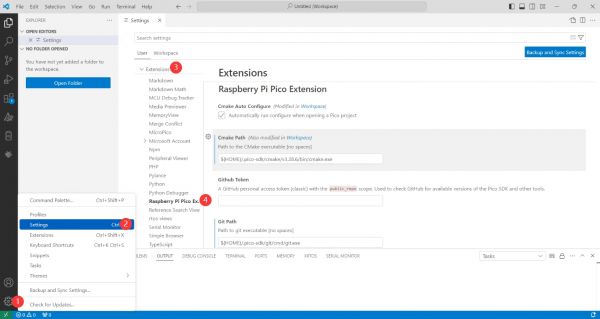
The configuration is as follows:Cmake Path: ${HOME}/.pico-sdk/cmake/v3.28.6/bin/cmake.exe Git Path: ${HOME}/.pico-sdk/git/cmd/git.exe Ninja Path: ${HOME}/.pico-sdk/ninja/v1.12.1/ninja.exe Python3 Path: ${HOME}/.pico-sdk/python/3.12.1/python.exe
New Project
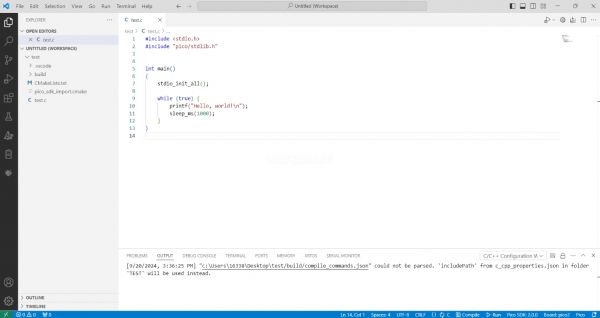
- The configuration is complete, create a new project, enter the project name, select the path, and click Create to create the project
To test the official example, you can click on the Example next to the project name to select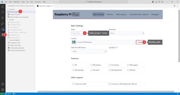
- The project is created successfully
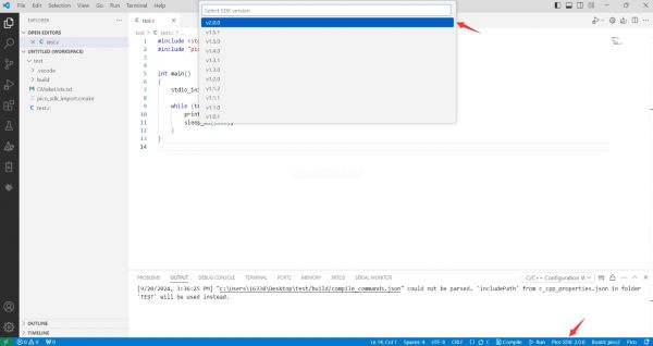
- Select the SDK version
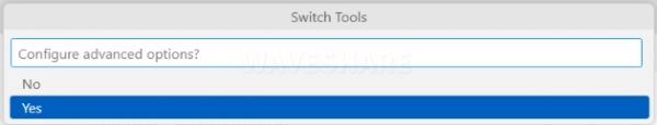
- Select Yes for advanced configuration
- Choose the cross-compilation chain, 13.2.Rel1 is applicable for ARM cores, RISCV.13.3 is applicable for RISCV cores. You can select either based on your requirements

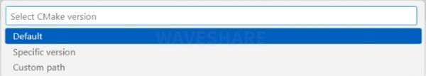
- Select default for CMake version (the path configured earlier)
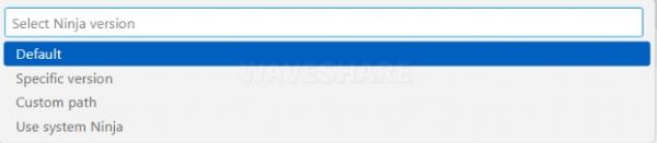
- Select default for Ninjaversion
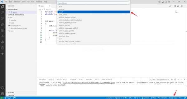
- Select the development board
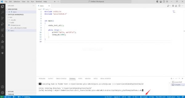
- Click Complie to compile
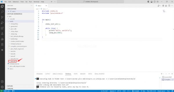
- The uf2 format file is successfully compiled
Import Project
- The Cmake file of the imported project cannot have Chinese (including comments), otherwise the import may fail
- To import your own project, you need to add a line of code to the Cmake file to switch between pico and pico2 normally, otherwise even if pico2 is selected, the compiled firmware will still be suitable for pico
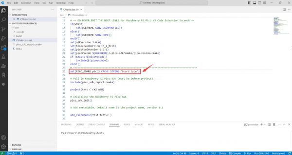
set(PICO_BOARD pico CACHE STRING "Board type")
Update Extension
- The extension version in the offline package is 0.15.2, and you can also choose to update to the latest version after the installation is complete
Arduino IDE Series
Install Arduino IDE
- First, go to Arduino official website to download the installation package of the Arduino IDE.

- Here, you can select Just Download.
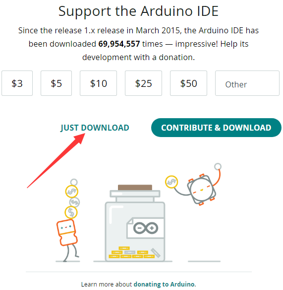
- Once the download is complete, click Install.
Notice: During the installation process, it will prompt you to install the driver, just click Install
Arduino IDE Interface
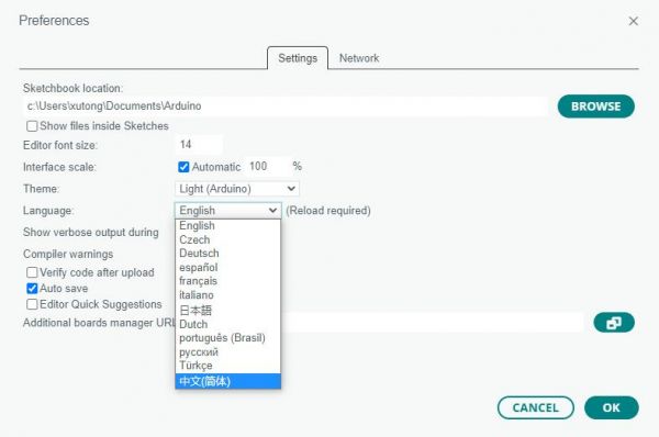
- After the first installation, when you open the Arduino IDE, it will be in English. You can switch to other languages in File --> Preferences, or continue using the English interface.

- In the Language field, select the language you want to switch to, and click OK.
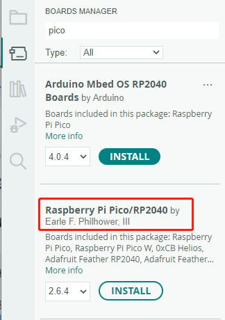
Install Arduino-Pico Core in Arduino IDE
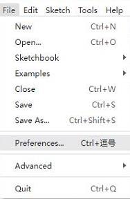
- Open the Arduino IDE, click on the file in the top left corner, and select Preferences
- Add the following link to the attached board manager URL, and then click OK
https://github.com/earlephilhower/arduino-pico/releases/download/4.0.2/package_rp2040_index.json
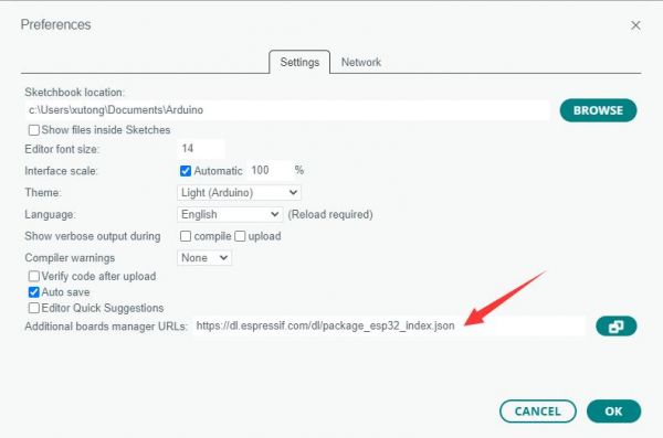
Note: If you already have an ESP32 board URL, you can use a comma to separate the URLs as follows:https://dl.espressif.com/dl/package_esp32_index.json,https://github.com/earlephilhower/arduino-pico/releases/download/4.0.2/package_rp2040_index.json
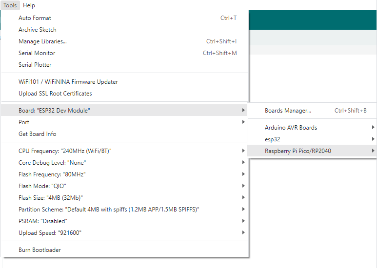
- Click Tools > Development Board > Board Manager > Search pico, as my computer has already been installed, it shows that it is installed
Upload Demo at the First Time
- Press and hold the BOOTSET button on the Pico board, connect the pico to the USB port of the computer via the Micro USB cable, and release the button after the computer recognizes a removable hard disk (RPI-RP2).
- Download the program and open D1-LED.ino under the arduino\PWM\D1-LED path
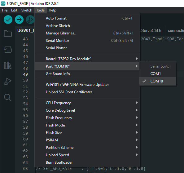
- Click Tools --> Port, remember the existing COM, do not click this COM (the COM displayed is different on different computers, remember the COM on your own computer)
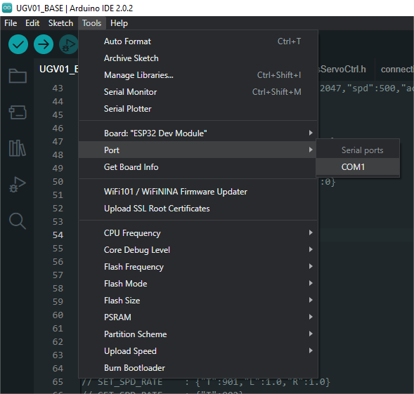
- Connect the driver board to the computer using a USB cable. Then, go to Tools > Port. For the first connection, select uf2 Board. After uploading, when you connect again, an additional COM port will appear
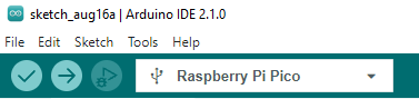
- Click Tools > Development Board > Raspberry Pi Pico > Raspberry Pi Pico or Raspberry Pi Pico 2
- After setting it up, click the right arrow to upload the program
- If issues arise during this period, and if you need to reinstall or update the Arduino IDE version, it is necessary to uninstall the Arduino IDE completely. After uninstalling the software, you need to manually delete all contents within the C:\Users\[name]\AppData\Local\Arduino15 folder (you need to show hidden files to see this folder). Then, proceed with a fresh installation.
Open Source Demos
MircoPython video demo (github)
MicroPython firmware/Blink demos (C)
Raspberry Pi official C/C++ demo (github)
Raspberry Pi official micropython demo (github)
Arduino official C/C++ demo (github)
GUI API Details
If you have used our SPI screen before, you should be familiar with this example program
C
Underlying Hardware Interfaces
We have encapsulated the underlying layer, and due to different hardware platforms, the internal implementation is different. If you need to understand the internal implementation, you can check the corresponding directory
You can see a lot of definitions in DEV_Config.c(.h), which can be found in the directory: c\lib\Config
- Data type:
#define UBYTE   uint8_t
#define UWORD   uint16_t
#define UDOUBLE uint32_t
- Module initialization and exit processing:
void DEV_Module_Init(void);
void DEV_Module_Exit(void);
Note:
1. Here are some GPIOs before and after using the LCD screen.
- GPIO read/write:
void 	DEV_Digital_Write(UWORD Pin, UBYTE Value);
UBYTE 	DEV_Digital_Read(UWORD Pin);
- SPI write data:
void DEV_SPI_WriteByte(UBYTE Value);
Upper Layer Applications
For the screen, what if you need to paint, display Chinese and English characters, display pictures, etc., these are all done by the upper layer applications. Many of you have asked about some graphics processing, and we have provided some basic functions here The GUI can be found in the directory: c\lib\GUI\GUI_Paint.c(.h)
In the following directory are the character fonts that the GUI depends on: c\lib\Fonts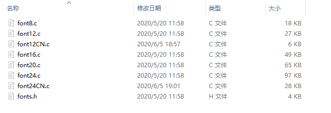
- New Image Property: Create a new image property that includes the name, width, height, angle of rotation, and color of the image cache
void Paint_NewImage(UWORD *image, UWORD Width, UWORD Height, UWORD Rotate, UWORD Color)
Parameters:
 	image:  The name of the image cache, which is actually a pointer to the first address of the image cache;
 	Width:  The width of the image cache;
 	Height: The height of image cache;
 	Rotate: The angle of image rotation;
 	Color:  The initial color of the image;
- Select Image Cache: The purpose of selecting the image cache is that you can create multiple image properties, and there can be multiple image caches. You can select each image you create
void Paint_SelectImage(UBYTE *image)
Parameters:
 	image: The name of the image cache, which is actually a pointer to the first address of the image cache;
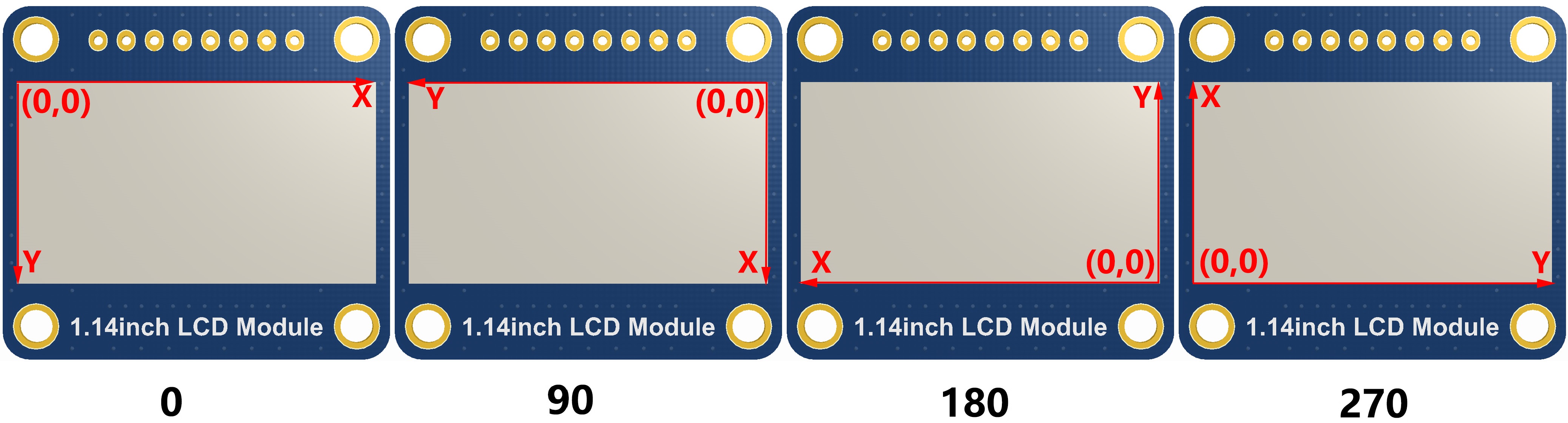
- Image Rotation: Set the rotation angle of the selected image, preferably after Paint_SelectImage (), you can choose to rotate 0, 90, 180, 270
void Paint_SetRotate(UWORD Rotate)
Parameters:
 	Rotate: Image rotation angles can be chosen as ROTATE_0, ROTATE_90, ROTATE_180, ROTATE_270 corresponding to 0, 90, 180, 270 degrees
- 【Note】Under different selection angles, the coordinates correspond to different starting pixels. Here taking 1.14 as an example, there are four images in sequence: 0°, 90°, 180°, 270°. For reference only
- Image Mirror Flip: Set the mirror flip of the selected image, you can choose no mirroring, horizontal mirroring, vertical mirroring, and mirroring around the image center
void Paint_SetMirroring(UBYTE mirror)
Parameters:
 	mirror: The mirroring method of the image can be selected as MIRROR_NONE, MIRROR_HORIZONTAL, MIRROR_VERTICAL, and MIRROR_ORIGIN, which correspond to no mirroring, horizontal mirroring, vertical mirroring, and mirroring around the image center, respectively
- Set the position and color of the point to be displayed in the cache: This is the core function of the GUI, handling point position and color displayed in the cache;
void Paint_SetPixel(UWORD Xpoint, UWORD Ypoint, UWORD Color)
Parameters:
 	Xpoint: The X position of the point in the image cache
 	Ypoint: The Y position of the point in the image cache
 	Color:  The color of the point
- Image cache fill color: Fill the image cache with a certain color, which is generally used as a screen whitening
void Paint_Clear(UWORD Color)
Parameters:
 	Color: The filled color
- Fill color of image cache window: Fill a certain part of the image cache window with a certain color, usually used as a window whitening function, commonly used for displaying time, whitening for one second
void Paint_ClearWindows(UWORD Xstart, UWORD Ystart, UWORD Xend, UWORD Yend, UWORD Color)
Parameters:
 	Xstart: The starting point X coordinate of the window
 	Ystart: The starting point Y coordinate of the window
 	Xend:   The endpoint X coordinate of the window
 	Yend:   The endpoint Y coordinate of the window
 	Color:  The filled color
- Draw a dot: In the image cache, draw a dot at (Xpoint, Ypoint), you can choose the color, the size, and the style of the dot
void Paint_DrawPoint(UWORD Xpoint, UWORD Ypoint, UWORD Color, DOT_PIXEL Dot_Pixel, DOT_STYLE Dot_Style)
Parameters:
 	Xpoint: The X coordinate of the dot
 	Ypoint: The Y coordinate of the dot
 	Color:  The filled color
 	Dot_Pixel: The size of the dots, which provides the default 8 sizes of dots
 	 	 typedef enum {
 	 	 	 DOT_PIXEL_1X1  = 1,	// 1 x 1
 	 	 	 DOT_PIXEL_2X2  , 		// 2 X 2
 	 	 	 DOT_PIXEL_3X3  , 	 	// 3 X 3
 	 	 	 DOT_PIXEL_4X4  , 	 	// 4 X 4
 	 	 	 DOT_PIXEL_5X5  , 		// 5 X 5
 	 	 	 DOT_PIXEL_6X6  , 		// 6 X 6
 	 	 	 DOT_PIXEL_7X7  , 		// 7 X 7
 	 	 	 DOT_PIXEL_8X8  , 		// 8 X 8
 	 	} DOT_PIXEL;
 	Dot_Style: The style of the dot, the method to expand the size of the dot is that, whether to expand from the dot as the center or from the dot as the lower left corner to the upper right
 	 	typedef enum {
 	 	   DOT_FILL_AROUND  = 1,
 	 	   DOT_FILL_RIGHTUP,
 	 	} DOT_STYLE;
- Draw a line: In the image cache, you can draw a line from (Xstart, Ystart) to (Xend, Yend) and choose the color, the width and the style of the line
void Paint_DrawLine(UWORD Xstart, UWORD Ystart, UWORD Xend, UWORD Yend, UWORD Color, LINE_STYLE Line_Style , LINE_STYLE Line_Style)
Parameters:
 	Xstart: The starting point X coordinate of the line
 	Ystart: The starting point Y coordinate of the line
 	Xend:   The endpoint X coordinate of the line
 	Yend:   The endpoint Y coordinate of the line
 	Color:  The filled color
 	Line_width: The width of the lines, which provides the default 8 widths
 	 	typedef enum {
 	 	 	 DOT_PIXEL_1X1  = 1,	// 1 x 1
 	 	 	 DOT_PIXEL_2X2  , 		// 2 X 2
 	 	 	 DOT_PIXEL_3X3  ,		// 3 X 3
 	 	 	 DOT_PIXEL_4X4  ,		// 4 X 4
 	 	 	 DOT_PIXEL_5X5  , 		// 5 X 5
 	 	 	 DOT_PIXEL_6X6  , 		// 6 X 6
 	 	 	 DOT_PIXEL_7X7  , 		// 7 X 7
 	 	 	 DOT_PIXEL_8X8  , 		// 8 X 8
 	 	} DOT_PIXEL;
 	 Line_Style: The style of the line, which selects whether the line is connected in a straight line or as a dashed line
 	 	typedef enum {
 	 	 	 LINE_STYLE_SOLID = 0,
 	 	 	 LINE_STYLE_DOTTED,
 	 	} LINE_STYLE;
- Draw a rectangle: In the image cache, you can draw a rectangle from (Xstart, Ystart) to (Xend, Yend) and choose the color, the width of the line, and whether to fill the inside of the rectangle
void Paint_DrawRectangle(UWORD Xstart, UWORD Ystart, UWORD Xend, UWORD Yend, UWORD Color, DOT_PIXEL Line_width, DRAW_FILL Draw_Fill)
Parameters:
 	Xstart: The starting point X coordinate of the rectangle
 	Ystart: The starting point Y coordinate of the rectangle
 	Xend:   The endpoint X coordinate of the rectangle
 	Yend:   The endpoint Y coordinate of the rectangle
 	Color:  The filled color
 	Line_width: The width of the four sides of the rectangle, providing the default 8 widths
 	 	typedef enum {
 	 	 	 DOT_PIXEL_1X1  = 1,	// 1 x 1
 	 	 	 DOT_PIXEL_2X2  , 		// 2 X 2
 	 	 	 DOT_PIXEL_3X3  ,		// 3 X 3
 	 	 	 DOT_PIXEL_4X4  ,		// 4 X 4
 	 	 	 DOT_PIXEL_5X5  , 		// 5 X 5
 	 	 	 DOT_PIXEL_6X6  , 		// 6 X 6
 	 	 	 DOT_PIXEL_7X7  , 		// 7 X 7
 	 	 	 DOT_PIXEL_8X8  , 		// 8 X 8
 	 	} DOT_PIXEL;
 	Draw_Fill: Filling, whether to fill the inside of the rectangle
 	 	typedef enum {
 	 	 	 DRAW_FILL_EMPTY = 0,
 	 	 	 DRAW_FILL_FULL,
 	 	} DRAW_FILL;
- Draw a circle: In the image cache, draw a circle with a radius of Radius with (X_Center Y_Center) as the center of the circle, and you can choose the color, the width of the line, and whether to fill the inside of the circle
void Paint_DrawCircle(UWORD X_Center, UWORD Y_Center, UWORD Radius, UWORD Color, DOT_PIXEL Line_width, DRAW_FILL Draw_Fill)
Parameters:
 	X_Center: The X coordinate of the center of the circle
 	Y_Center: The Y coordinate of the center of the circle
 	Radius:  The radius of the circle
 	Color:    The filled color
 	Line_width: The width of the arc, which provides the default 8 widths
 	 	typedef enum {
 	 	 	 DOT_PIXEL_1X1  = 1,	// 1 x 1
 	 	 	 DOT_PIXEL_2X2  , 		// 2 X 2
 	 	 	 DOT_PIXEL_3X3  ,		// 3 X 3
 	 	 	 DOT_PIXEL_4X4  ,		// 4 X 4
 	 	 	 DOT_PIXEL_5X5  , 		// 5 X 5
 	 	 	 DOT_PIXEL_6X6  , 		// 6 X 6
 	 	 	 DOT_PIXEL_7X7  , 		// 7 X 7
 	 	 	 DOT_PIXEL_8X8  , 		// 8 X 8
 	 	} DOT_PIXEL;
 	Draw_Fill: Filling, whether to fill the inside of the circle
 	 	typedef enum {
 	 	 	 DRAW_FILL_EMPTY = 0,
 	 	 	 DRAW_FILL_FULL,
 	 	} DRAW_FILL;
- Write Ascii characters: In the image cache, with (Xstart Ystart) as the left vertex, write an Ascii character, and you can select the Ascii code visual character font library, font foreground color, and font background color
void Paint_DrawChar(UWORD Xstart, UWORD Ystart, const char Ascii_Char, sFONT* Font, UWORD Color_Foreground, UWORD Color_Background)
Parameters:
 	Xstart: The left vertex X coordinate of the character
 	Ystart: The left vertex Y coordinate of the character
 	Ascii_Char: Ascii character
 	Font: The Ascii code visual character font library, provides the following fonts in the Fonts folder:
 	 	font8: 5*8 font
 	 	font12: 7*12 font
 	 	font16: 11*16 font
 	 	font20: 14*20 font
 	 	font24: 17*24 font
 	Color_Foreground: Font color
 	Color_Background: Background color
- Write English strings: In the image cache, write a string of English characters with (Xstart Ystart) as the left vertex, and you can select the Ascii code visual character font library, font foreground color, and font background color
void Paint_DrawString_EN(UWORD Xstart, UWORD Ystart, const char * pString, sFONT* Font, UWORD Color_Foreground, UWORD Color_Background)
Parameters:
 	Xstart:  The left vertex X coordinate of the character
 	Ystart:  The left vertex Y coordinate of the character
 	pString: A string, a string is a pointer
 	Font: The Ascii code visual character font library, provides the following fonts in the Fonts folder:
 	 	font8: 5*8 font
 	 	font12: 7*12 font
 	 	font16: 11*16 font
 	 	font20: 14*20 font
 	 	font24: 17*24 font
 	Color_Foreground: Font color
 	Color_Background: Background color
- Write Chinese strings: In the image cache, write a string of Chinese characters with (Xstart Ystart) as the left vertex, and you can select the GB2312 encoding character font library, font foreground color, and font background color
void Paint_DrawString_CN(UWORD Xstart, UWORD Ystart, const char * pString, cFONT* font, UWORD Color_Foreground, UWORD Color_Background)
Parameters:
 	Xstart:  The left vertex X coordinate of the character
 	Ystart:  The left vertex Y coordinate of the character
 	pString: A string, a string is a pointer
 	Font: The GB2312 encoding character library, the following fonts are provided in the Fonts folder:
 	 	font12CN: Ascii character font 11*21, Chinese font 16*21
 	 	font24CN: Ascii character font 24*41, Chinese font 32*41
 	Color_Foreground: Font color
 	Color_Background: Background color
- Write numbers: In the image cache, write a string of numbers with (Xstart Ystart) as the left vertex, and you can select the Ascii code visual character font library, font foreground color, and font background color
void Paint_DrawNum(UWORD Xpoint, UWORD Ypoint, double Nummber, sFONT* Font, UWORD Digit,UWORD Color_Foreground, UWORD Color_Background);
Parameters:
 	Xstart:  The left vertex X coordinate of the character
 	Ystart:  The left vertex Y coordinate of the character
 	Number: The displayed number, here is stored in a 32-bit long int type, which can be displayed up to 2147483647.
 	Font: The Ascii code visual character font library, provides the following fonts in the Fonts folder:
 	 	font8: 5*8 font
 	 	font12: 7*12 font
 	 	font16: 11*16 font
 	 	font20: 14*20 font
 	 	font24: 17*24 font
        Digit: Display decimal places
 	Color_Foreground: Font color
 	Color_Background: Background color
- Display time: In the image cache, display time with (Xstart Ystart) as the left vertex, and you can select the Ascii code visual character font library, font foreground color, and font background color
void Paint_DrawTime(UWORD Xstart, UWORD Ystart, PAINT_TIME *pTime, sFONT* Font, UWORD Color_Background, UWORD Color_Foreground)
Parameters:
 	Xstart: The left vertex X coordinate of the character
 	Ystart: The left vertex Y coordinate of the character
 	pTime:  The displayed time, here defines a time structure, just pass the numbers of the hour, minute, second to the parameters
 	Font: The Ascii code visual character font library, provides the following fonts in the Fonts folder:
 	 	font8: 5*8 font
 	 	font12: 7*12 font
 	 	font16: 11*16 font
 	 	font20: 14*20 font
 	 	font24: 17*24 font
 	Color_Foreground: Font color
 	Color_Background: Background color
QMI8658
- Module initialization
unsigned char QMI8658_init(void);
- Read data
void QMI8658_read_xyz(float acc[3], float gyro[3], unsigned int *tim_count);
Parameters:
	 float acc[3]: The array that stores acceleration values, represented as floating-point numbers, contains three elements, which are acceleration on the X, Y, and Z axes
	 float gyro[3]: The array that stores gyroscope values, represented as floating-point numbers, contains three elements, which are angular velocities on the X, Y, and Z axes
Python
Underlying Hardware Interface
- Module initialization
def __init__(self)
- Send a command
def write_cmd(self, cmd)
- Send data
def write_data(self, buf)
- Adjust backlight
def set_bl_pwm(self,duty)
Drawing GUI
- Import a library
import framebuf
- Create an object
The custom class LCD_1inch28 inherits the framebuf.FrameBuffer class from MicroPython, which provides many methods to draw images, let's create the LCD_1inch28 class object first
LCD = LCD_1inch28()
- Draw a line
LCD.line(x1, y1, x2, y2, color)
Parameters:
	x1, y1: The x and y coordinates of the starting point
	x2, y2: The x and y coordinates of the endpoint
	color:  The color of the line
- Draw a rectangle
LCD.fill_rect(x1, y1, w, h, color)
Parameters:
	x1, y1: The x and y coordinates of the upper left corner of the rectangle
        w, h:   The width and height of the rectangle
        color:  The filling color of the rectangle
- Draw text
LCD.text(str, x, y, color)
Parameters:
         str:   Display text
	 x, y:  The x and y coordinates of the upper left corner of the text
         color: The color of the text
- Change the text size
LCD.write_text(str, x, y, size, color)
Parameters:
	 size: The difference between this function and LCD.text is that it supports custom font size, which is used to specify the font size
- Display
LCD.show()
QMI8658
- Create an object
qmi8658=QMI8658()
- Read and parse the XYZ data of the sensor
xyz=qmi8658.Read_XYZ()
Return values:
          xyz[0]~xyz[2]: The function returns an array, with the first three elements representing acceleration on the X, Y, and Z axes
	  xyz[3]~xyz[5]: These three elements represent the angular velocities on the X, Y, and Z axes
LVGL Demos
C
Example Demonstration
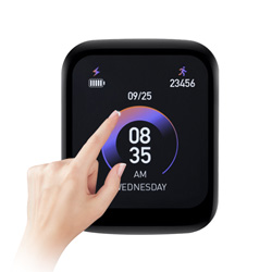
This example shows four interfaces that can be switched by swiping on the touchscreen.
- The first interface
- Display content: The logo of Waveshare Electronics
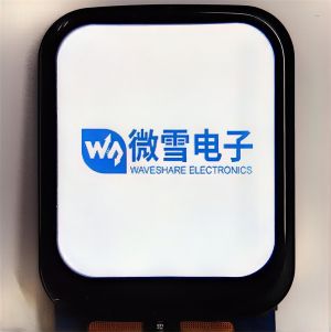
- Display content: The logo of Waveshare Electronics
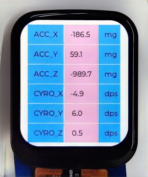
- The second interface
- Display content: Data from the IMU sensor
- Refresh rate: Updated every 500ms
- The third interface
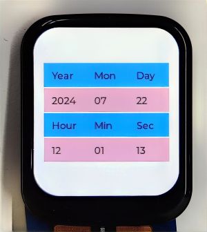
- Display content: RTC date and time data
- Refresh rate: Updated every 300ms

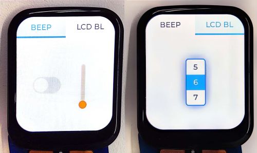
- The fourth interface:
- Display content: two interfaces for controlling buzzer and LCD backlight.
- Interaction method: There are two options at the top of the interface: BEEP and LCD BL. You can touch the top option to switch to the corresponding control interface. BEEP is the buzzer control interface, which contains a switch and a slider. The switch is used to control the buzzer start/stop and the slider is used to control the buzzer frequency. LCD BL is the LCD backlight control interface, in this interface, you can control the brightness of the screen by scrolling the wheel.

Example Introduction
This example is used to test the LVGL widdet interaction and style beautification, etc.. For specific development of LVGL, please refer to LVGL development documentation.
Implement Function
- In this example, DMA is used to transfer color data to the SPI bus, reducing CPU utilization, and controlling CPU usage to less than 50% and memory usage to less than 35% during simple interactions.
- The example system clock is 200MHz. The peripheral clock frequency for SPI is set to match the system clock, and the LVGL library's dual buffer mechanism is utilized. Data transfer occurs in one buffer while the other buffer is rendering, ensuring smooth animation.
- This example uses a touch screen switching interface to realize real-time display of six-axis sensors, RTC data, and real-time control of buzzer switching, frequency, and screen brightness through the widget, demonstrating the simple use of LVGL widgets.
Compile and Run
- Windows
- Refer to Windows Environment Setup Tutorial to complete the environment setup
- Open VS 2022 -> Tool -> Command Line -> Developer Powershell
- Set the absolute address of pico-sdk as PICO_SDK_PATH, for example, set pico-sdk address as“D:\pico\pico-sdk”
setx PICO_SDK_PATH "D:\pico\pico-sdk"
- Download the demo, enter the source code directory, if the build directory already exists, you can go directly into it. If not, you can create this directory:
mkdir build
cd build
- Execute cmake, automatically generate the Makefile file:
cmake -G "NMake Makefiles" ..
- Execute nmake to generate the executable file, and input the following commands in the terminal:
nmake
After compilation, it will generate a .uf2 formatted file. - Press the onboard boot key, connect the board to the USB interface of the PC through a Micro USB cable. And then release the key, the PC will identify the pico as a removable driver. Finally, you need to copy the compiled file in .uf2 format to Pico.
- Ubuntu
- Refer to Chapter 2. The SDK of Pico Getting Started to complete the environment setup
- Open a terminal, set the value of the environment variable PICO_SDK_PATH to the absolute path of pico-sdk, for example, if my pico-sdk path is “/home/pico/pico-sdk”
nano ~/.bashrc
#Add the following content at the last line
export PICO_SDK_PATH="/home/pico/pico-sdk"
- After setting, save and exit. The configuration takes effect
source ~/.bashrc
- Download the demo, enter the source code directory, if the build directory already exists, you can go directly into it. If not, you can create this directory:
mkdir build
cd build
- Execute cmake, it will generate Makefile file:
cmake ..
- Execute nmake to generate the executable file, and input the following content in the terminal:
nmake
After compilation, it will generate a .uf2 formatted file. - Press the onboard boot key, connect the board to the USB interface of the PC through a Micro USB cable. And then release the key, the PC will identify the pico as a removable driver. Finally, you need to copy the compiled file in .uf2 format to Pico.
Source Code Analysis
Source Code Structure
- The source code of the LVGL library is at lib/lvgl of the project file folder, and the version used is "8.1". For secondary development, please refer to the development documentation corresponding to the used version.
- The related settings for the LVGL library are at examples/inc/lv_conf.h of the project file folder, where you can set display refresh rates, system usage data, and so on.
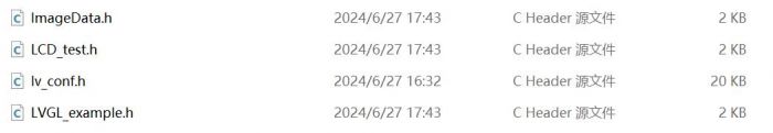
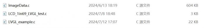
- The application code for the LVGL library is located in the project folder at examples/src/LVGL_example.c.
LVGL Initialization
Before using LVGL image library, you need to initialize LVGL.
- The initialization function for the LVGL library
- Demo location: examples/src/LVGL_example.c
- Implementation function: Mainly used to initialize the hardware and structure variables required for LVGL.
LVGL_Init();
- LVGL library core initialization
- Demo location: examples/src/LVGL_example.c
/*2.Init LVGL core*/
lv_init();
LVGL Running
The LVGL library calls the heartbeat function lv_tick_inc at regular intervals to notify LVGL of the elapsed time so that LVGL can update its internal time state and handle time-related tasks such as animations, timers, etc. The lv_task_handler function also needs to be called in the loop of the main function so that LVGL can handle events and tasks in time to ensure that the user interface responds and refreshes.
- LVGL heartbeat function:
- Demo location: examples/src/LVGL_example.c
- Implementation method: It is necessary to ensure that the priority of lv_task_handler is lower than the priority of lv_tick_inc. Therefore, in this example, lv_tick_inc is called within the timer callback function.
//Timer callback function called every 5ms
add_repeating_timer_ms(5, repeating_lvgl_timer_callback, NULL, &lvgl_timer);

static bool repeating_lvgl_timer_callback(struct repeating_timer *t)
{
    lv_tick_inc(5);
    return true;
}
- LVGL Task Processor
- Demo location: examples/src/LCD_XinXX_LVGL_test.c
- Implementation method: To handle LVGL tasks, you need to regularly call lv_timer_handler(), in this example, it is called in the loop of the main function.
int main()
{
    ...
    while(1)
    {
      lv_task_handler();
      DEV_Delay_ms(5);
      ...
    }

}
LVGL Display
To implement LVGL display, you must initialize a display driver and set the various properties of the display driver, such as color format, draw buffer, rendering mode, and display callback function. At each LV_DISP_DEF_REFR_PERIOD (set in lv_conf.h), LVGL detects if something has happened on the UI that needs to be redrawn. For example, a button is pressed, a chart is changed, an animation occurs, etc. When redrawing is needed, LVGL calls the display callback function to complete the drawing of the image in the refresh area.
- LVGL display refreshing rate
- Demo location: examples/inc/lv_conf.h
- Setting method: In the lv_conf.h file, you can also set the display buffer refresh rate. You can modify this definition to change the screen refresh time.
#define LV_DISP_DEF_REFR_PERIOD 10 // Unit: ms, here is 10ms
- LVGL display color setting
- Demo location: examples/inc/lv_conf.h
- Purpose of setting: Since the pixel color storage method constructed by the lv_color_t structure in its default state does not match the data to be transmitted in this example, direct transmission would result in color discrepancies in the displayed image.
#define LV_COLOR_16_SWAP 1
- LVGL display related variable definition
- Demo location: examples/src/LVGL_example.c
- Implementation function: Define the display driver disp_drv, draw the buffer disp_buf. This example implements a double buffering mechanism, with the drawing buffer composed of buffers buf0 and buf1, both set to half the size of the screen display area, which can reduce jagged edges during large area refreshing while effectively improving screen refresh rate; when using a single buffer, it is best to set it to 10% of the screen display area, which can effectively reduce system usage but may result in noticeable jagged edges during large area refresh of image.
static lv_disp_drv_t disp_drv;
static lv_disp_draw_buf_t disp_buf;
static lv_color_t buf0[DISP_HOR_RES * DISP_VER_RES/2];
static lv_color_t buf1[DISP_HOR_RES * DISP_VER_RES/2];
- LVGL display device registration
- Demo location: examples/src/LVGL_example.c
- Implementation function: According to the design requirements, improve the core structure variables of the LVGL library, initialize the display driver disp_drv, and set the drawing buffer, which is a simple array used by LVGL to render screen content. Once the rendering is ready, the content of the draw buffer will be sent to the display using the disp_drv_flush_cb function set in the display driver.
/*3.Init LVGL display*/
lv_disp_draw_buf_init(&disp_buf, buf0, buf1, DISP_HOR_RES * DISP_VER_RES / 2);
lv_disp_drv_init(&disp_drv);
disp_drv.flush_cb = disp_flush_cb;
disp_drv.draw_buf = &disp_buf;
disp_drv.hor_res = DISP_HOR_RES;
disp_drv.ver_res = DISP_VER_RES;
lv_disp_t *disp= lv_disp_drv_register(&disp_drv);
- LVGL display callback function
- Demo location: examples/src/LVGL_example.c
- Implementation function: Mainly complete the drawing of the image in the refresh area.
void disp_flush( lv_disp_drv_t *disp_drv, const lv_area_t *area, lv_color_t *color_p )
Parameters:
    lv_disp_drv_t *disp_drv:  Displays driver structure pointers, which contain information about the display and function pointers. This parameter is often used to notify you that a refresh is complete
    const lv_area_t *area  : Region structure pointer, containing the position information of the area to be refreshed. In this case, the window used to create the TFT display
    lv_color_t *color_p    : Color structure pointer, indicating the color data to be displayed in the refresh area. In this demo, it reads the address as DMA input to transmit data to the SPI bus and completes the image drawing
- LVGL display callback function implementation
- Demo location: examples/src/LVGL_example.c
- Implementation method: In this example, to maximize the reduction of processor utilization, DMA is used for color data transmission. color_p is set as the read address, and the SPI bus output data register is set as the write address.
static void disp_flush_cb(lv_disp_drv_t * disp, const lv_area_t * area, lv_color_t * color_p)
{
    LCD_SetWindows(area->x1, area->y1, area->x2+1, area->y2+1);
    DEV_Digital_Write(LCD_DC_PIN, 1);
    DEV_Digital_Write(LCD_CS_PIN, 0);
    dma_channel_configure(dma_tx,
                          &c,
                          &spi_get_hw(LCD_SPI_PORT)->dr,
                          color_p, // read address
                          ((area->x2 + 1 - area-> x1)*(area->y2 + 1 - area -> y1))*2,
                          true);
}
- LVGL refresh completion notification implementation
- Demo location: examples/src/LVGL_example.c
- Implementation function: The LVGL core needs to be notified after each image refresh is completed, so that LVGL can prepare the next refresh image for rendering.
- Implementation method: In this example, the completion of the DMA transmission is notified in the interrupt service function for LVGL image refresh. If a blocking notification mechanism is used, it is not possible to utilize the double buffering mechanism to increase the refresh rate.
static void dma_handler(void)
{
    if (dma_channel_get_irq0_status(dma_tx)) {
        dma_channel_acknowledge_irq0(dma_tx);
        DEV_Digital_Write(LCD_CS_PIN, 1);
        lv_disp_flush_ready(&disp_drv);
    }
}
LVGL Input
In LVGL, users can register input devices such as touchpads, mice, keyboards, or encoders, etc. Users can control the user interface through these input devices to achieve better interaction.
- LVGL calls input device callback functions for frequency settings
- Demo location: examples/inc/lv_conf.h
- Setting method: By default, LVGL calls the input device callback function every 30ms to update the events triggered by the input device, which can be set in lv_conf.h.
#define LV_INDEV_DEF_READ_PERIOD 30 // Unit: ms, here is 30ms
- LVGL input device registration
- Demo location: examples/src/LVGL_example.c
- Setting method: Register touchscreen device indev_ts and initialize it
/*4.Init touch screen as input device*/
lv_indev_drv_init(&indev_ts);           // Device initialization
indev_ts.type = LV_INDEV_TYPE_POINTER;  // Register it as touchscreen device
indev_ts.read_cb = ts_read_cb;          // Set callback function
lv_indev_t * ts_indev = lv_indev_drv_register(&indev_ts); // Register device
DEV_IRQ_SET(Touch_INT_PIN, GPIO_IRQ_EDGE_RISE, &touch_callback); //Enable touch interrupt
- LVGL input device callback function
- Demo location: examples/src/LVGL_example.c
- Implementation function: Mainly used to update input events
static void ts_read_cb(lv_indev_drv_t * drv, lv_indev_data_t*data);
Parameters:
  lv_indev_drv_t *indev_drv: Pointer to the input device driver structure in LVGL. In this case, the structure is for a touch screen input device driver
  lv_indev_data_t *data    : Pointer to the input device data structure in LVGL. In this case, the structure is used to store the status and data of the input device, including the current touch state (pressed or released) and the coordinates of the touch points
- Callback function implementation of touch screen input device
- Demo location: examples/src/LVGL_example.c
- Implementation method: It is mainly to update the touch state and touch point coordinates of the touch screen through touch interrupt.
static void touch_callback(uint gpio, uint32_t events)
{
    if (gpio == Touch_INT_PIN)
    {
        CST816S_Get_Point();
        gesture = CST816S_Get_Gesture();
        ts_x = Touch_CTS816.x_point;
        ts_y = Touch_CTS816.y_point;
        ts_act = LV_INDEV_STATE_PRESSED;
    }
}

static void ts_read_cb(lv_indev_drv_t * drv, lv_indev_data_t*data)
{
    data->point.x = ts_x;
    data->point.y = ts_y;
    data->state = ts_act;
    ts_act = LV_INDEV_STATE_RELEASED;
}
LVGL Widget Layout
In LVGL, we can create various user interfaces. The basic components of the interface are objects, also called widgets, such as buttons, labels, images, lists, charts, or text areas. In a interface, we can create multiple widgets simultaneously and set their positions, sizes, parent objects, styles, and event handlers and other basic properties.
- LVGL widget initialization
- Demo location: examples/src/LVGL_example.c
- Implementation function: It primarily used for stylized widgets and layout widgets.
void Widgets_Init(void);
- LVGL create tile
- Demo location: examples/src/LVGL_example.c
- Implementation function: A Tile view is a container object whose elements, called tiles, can be arranged in a grid format. Users can navigate between tiles by swiping. Call lv_tileview_add_tile(tileview, row_id, col_id, dir) to create a new tile at row_id row and col_id column. dir can be LV_DIR_LEFT/RIGHT/TOP/BOTTOM/HOR/VER/ALL or a value to move to the adjacent tile in the given direction by sliding.
//Create a tile at (0,0) with support for sliding down to (0,1)
tile1 = lv_tileview_add_tile(tv, 0, 0, LV_DIR_BOTTOM);
- LVGL create widget
- Demo location: examples/src/LVGL_example.c
- Implementation function: To create a widget, different widgets need to use different function interfaces, you can choose the parent object to create it.
//Create a widget where tab1 is the parent object of the key, which can be replaced with a widget such as list, title, etc. that can have child objects
sw = lv_switch_create(tab1);
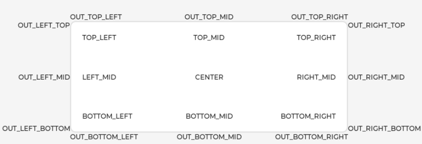
- Alignment positioning of LVGL widget
- Demo location: examples/src/LVGL_example.c
- Implementation function: Enable a widget to be offset and positioned based on a reference point. The widget aligns to the center of the offset reference point widget.
- Alignment standard: The LVGL library supports both internal and external alignments. By default, the upper-left corner is the origin, the leftward as the positive horizontal direction, and the downward as the positive vertical direction.
//Position the btn widget 45 pixels to the left from the center point
lv_obj_align(sw, LV_ALIGN_CENTER, -45, 0);

- LVGL widget to adjust font size
- Demo location: examples/inc/lv_conf.h and examples/src/LVGL_example.c
- Implementation function: In actual use, an interface may need to use multiple font sizes. Multiple font sizes can be enabled in lv_conf.h and the default font size can be set. When setting the font size, it is necessary to stylize the widget so that it can be rendered according to the set style. The lv_obj_add_style function can be used to render various parts of the widget in different states.
#define LV_FONT_MONTSERRAT_16 1                                // Enable font 16
#define LV_FONT_MONTSERRAT_18 1                                // Enable font 18
#define LV_FONT_DEFAULT &lv_font_montserrat_18                 // Set the default font size as 18

static lv_style_t style_label;
lv_style_init(&style_label);                                   // Initialize style
lv_style_set_text_font(&style_label, &lv_font_montserrat_16);  // Set the font size as 16
lv_obj_add_style(label,&style_label,0);                        // Set label theme style
- LVGL widget event handling
- Demo location: examples/src/LVGL_example.c
- Implementation function: In LVGL, you can add an event handler callback function to a widget so that when the widget is clicked, scrolled, redrawn, etc., it triggers an event and enters the event handler callback function. Call lv_obj_add_event_cb(obj, event_cb, filter, user_data) function in the program to add the event filter handling function event_cb for the widget obj, when the widget obj triggers the filter event, the system will automatically call the event_cb function. The last parameter is a pointer to any custom data available in the event.
//Add handler function sw_event_cb for event LV_EVENT_VALUE_CHANGED to widget sw
lv_obj_add_event_cb(sw, sw_event_cb,LV_EVENT_VALUE_CHANGED,NULL);
Python
Example Demonstration
This example shows four interfaces that can be switched by swiping on the touchscreen.
- The first interface:
- Display content: The logo of Waveshare Electronics

- Display content: The logo of Waveshare Electronics
- The second interface:
- Display content: Data from the IMU sensor
- Refresh rate: Updated every 500ms

- The third interface:
- Display content: RTC date and time data
- Refresh rate: Updated every 300ms
- The fourth interface:
- Display content: two interfaces for controlling buzzer and LCD backlight.
- Interaction method: There are two options at the top of the interface: BEEP and LCD BL. You can touch the top option to switch to the corresponding control interface. BEEP is the buzzer control interface, which contains a switch and a slider. The switch is used to control the buzzer start/stop and the slider is used to control the buzzer frequency. LCD BL is the LCD backlight control interface, in this interface, you can control the brightness of the screen by scrolling the wheel.
Example
This demo is for testing LVGL widget interaction, style design and so on. The version used is 9.1. As the development document of LVGL V9 does not provide Python example, you can refer to LVGL LVGL development documentation.
Implement Function
- The example system clock is 240MHz. The peripheral clock frequency for SPI is set to match the system clock, and the LVGL library's dual buffer mechanism is utilized. Data transfer occurs in one buffer while the other buffer is rendering, ensuring smooth animation.
- This example uses a touch screen switching interface to realize real-time display of six-axis sensors, RTC data, and real-time control of buzzer switching, frequency, and screen brightness through the widget, demonstrating the simple use of LVGL widgets.
Compile and Run
- Operation steps
- Before starting to use, it is necessary to set up an integrated development environment Thonny Python IDE (Windows version V3.3.3)
- Download the demo, and press the onboard boot key, connect the board to the USB interface of the PC through a Micro USB cable. And then release the key, the PC will identify the pico as a removable driver. Finally, you need to copy the compiled file in .uf2 format to Pico.
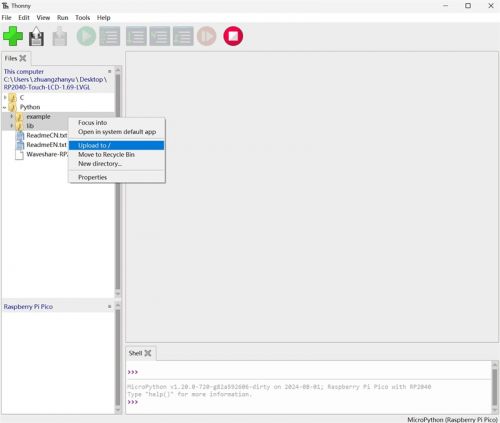
- Open Thonny, upload the examples and lib directories to the development board
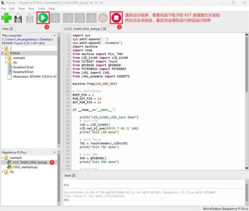
- Open the LCD_1in69_LVGL_test.py file under the examples directory, please refer to the steps below to run the demo
- Firmware building
- Envitonment building: only test on Ubuntu 22.04
- Github: lv_micropython
- Refer to Raspberry Pi Pico port to compile
- Firmware generation path: lv_micropython/ports/rp2/build-PICO/firmware.uf2
Source Code Analysis
Source Code Structure
- For LVGL library source code, you can refer to lv_micropython
- The related setting of the LVGL library is at lv_micropython/lib/lv_bindings/lv_conf.h file folder, which sets the refreshing frequency of the display, system occupied data and so on.
- The application code for the LVGL library is located in examples/src/LVGL_example.c and lib/LVGL.py folders of the project folder.
LVGL Initialization
Before using LVGL image library, you need to import the LVGL library and initialize the LVGL objects
- Import an LVGL library
- Demo location: lib/LVGL.py
- Implementation function: Import LVGL library and use alias "lv" to facilitate calling its functions
import lvgl as lv
- Create an LVGL object
- Demo location: examples/LCD_1in69_LVGL_test.py
- Implementation function: Create an LVGL object and pass in LCD and TSC objects as parameters
# Init LVGL
LVGL(LCD=LCD,TSC=TSC)
- LVGL initialization
- Demo location: lib/LVGL.py
- Code description: LVGL core initializes the initialization function located in the LVGL class, which is automatically called when the LVGL object is created
if not lv.is_initialized(): lv.init()
LVGL Running
The LVGL library periodically calls the heartbeat interface function lv.tick_inc to inform LVGL of the past time so that LVGL can update its internal time state to handle time-related tasks such as animations, timers, and so on. In addition, the lv.task_handler function needs to be called so that LVGL can handle events and tasks in time to ensure that the user interface responds and refreshes.
- LVGL Running interface
- Demo location: lib/LVGL.py
- Implementation method: Create an event_loop object. In the initialization function of this class, we create a timer. The timer will automatically call the heartbeat interface function and event handler function within a set time interval. The time interval for the call can be adjusted by passing the freq parameter, such as lv_utils.event_loop(freq=200), which defaults to 40 ms.
# Create event loop if not yet present
if not lv_utils.event_loop.is_running(): self.event_loop=lv_utils.event_loop()
- LVGL heartbeat interface
- Demo location: lib/lv_utils.py
- Implementation method: You need to make sure that the priority of lv.task_handler is lower than that of lv.tick_inc , so in this case, lv.tick_inc is called in the timer callback function.
#Timer callback function called every 5ms
self.timer.init(mode=Timer.PERIODIC, period=self.delay, callback=self.timer_cb) // In this case, self.delay = 5

def timer_cb(self, t):
    lv.tick_inc(self.delay)
    if self.scheduled < self.max_scheduled:
        try:
            micropython.schedule(self.task_handler_ref, 0)
            self.scheduled += 1 # The number of tasks being processed has increased
        except:
            pass
- LVGL Task Processor
- Demo location: lib/lv_utils.py
- Implementation method: To handle LVGL tasks, you need to call lv.task_handler at regular intervals, in this case after calling lv.tick_inc in the timer callback function.
def task_handler(self, _):
    try:
        if lv._nesting.value == 0:
            lv.task_handler()
            if self.refresh_cb: self.refresh_cb()
        self.scheduled -= 1 # The number of tasks being processed has decreased
    except Exception as e:
        if self.exception_sink:
            self.exception_sink(e)
LVGL Display
To implement LVGL display, you must initialize a display driver and set the various properties of the display driver, such as color format, draw buffer, rendering mode, and display callback function. At each LV_DEF_REFR_PERIOD (set in lv_conf.h), LVGL detects if something has happened on the UI that needs to be redrawn. For example, a button is pressed, a chart is changed, an animation occurs, etc. When redrawing is needed, LVGL calls the display callback function to complete the drawing of the image in the refresh area.
- LVGL display refreshing rate
- Demo location: lv_micropython/lib/lv_bindings/lv_conf.h
- Setting method: In lv_conf.h, you can modify LV_DEF_REFR_PERIOD to change the refresh time of the screen.
#define LV_DEF_REFR_PERIOD 10 // Unit: ms, here is 10ms
- LVGL display related variable definition
- Demo location: lib/LVGL.py
- Implementation function: The sizes of buf0 and buf1 are set to 33% of the screen display area to implement the LVGL dual buffer mechanism, which reduces the appearance of jagged edges during large area refresh of screen updates while effectively increasing the screen refresh rate; when using a single buffer, it is best to set it to 10% of the screen display area, which can effectively reduce system usage but may result in noticeable jagged edges during large area refresh of image.
# Init LVGL display
buf1 = lv.draw_buf_create(self.LCD.width, self.LCD.height // 3 , color_format, 0)
buf2 = lv.draw_buf_create(self.LCD.width, self.LCD.height // 3, color_format, 0)
- LVGL display device registration
- Demo location: lib/LVGL.py
- Implementation function: According to the design requirements, improve the core structure variables of the LVGL library, initialize the display driver disp_drv, and set the drawing buffer, which is a simple array used by LVGL to render screen content. Once the rendering is ready, the content of the draw buffer will be sent to the display using the disp_drv_flush_cb function set in the display driver.
self.disp_drv = lv.display_create(self.LCD.width, self.LCD.height) # Create a display driver object and set the width and height
self.disp_drv.set_color_format(color_format) # Set color format to RGB565
self.disp_drv.set_draw_buffers(buf1, buf2)   # Set the drawing buffer
self.disp_drv.set_render_mode(lv.DISPLAY_RENDER_MODE.PARTIAL) # Set the rendering mode to partial refresh mode
self.disp_drv.set_flush_cb(self.disp_drv_flush_cb) # Set display callback function
- LVGL display callback function
- Demo location: lib/LVGL.py
- Implementation function: Mainly complete the drawing of the image in the refresh area.
def disp_drv_flush_cb(self,disp_drv,area,color_p)
Parameters:
    disp_drv : Displays driver structure pointers, which contain information about the display and function pointers. This parameter is often used to notify you that a refresh is complete
    area     : Region structure pointer, containing the position information of the area to be refreshed. In this demo, you can use it for creating TFT display window.
    color_p     : Color structure pointer, indicating the color data to be displayed in the refresh area. In this demo, it reads the address as DMA input to transmit data to the SPI bus and completes the image drawing
- LVGL display callback function implementation
- Demo location: lib/LVGL.py
- Implementation method: In this example, to maximize the reduction of processor utilization, DMA is used for color data transmission. color_p is set as the read address, and the SPI bus output data register is set as the write address. The code is long and only shows part of it, please download the demo to view the full code.
def disp_drv_flush_cb(self,disp_drv,area,color_p):
    self.rp2_wait_dma() # Wait for DMA to be idle

    ......
    self.rgb565_swap_func(data_view, size)  # Convert color format

    self.LCD.setWindows(area.x1, area.y1, area.x2+1, area.y2+1) # Set LVGL interface display position

    ...... # DMA configuration

    self.rp2_dma.enable() # Enable DMA

    self.rp2_wait_dma() # Wait for DMA to be idle

    self.disp_drv.flush_ready() # Notify LVGL that data transfer is complete
}
LVGL Input
In LVGL, users can register input devices such as touchpads, mice, keyboards, or encoders, etc. Users can control the user interface through these input devices to achieve better interaction.
- LVGL calls input device callback functions for frequency settings
- Demo location: lv_micropython/lib/lv_bindings/lv_conf.h
- Setting method: It uses the same macro as the screen refresh time, and the input device callback function is called every 10ms to update the events triggered by the input device, and this can be set by modifying the LV_DEF_REFR_PERIOD definition.
#define LV_DEF_REFR_PERIOD 10 // Unit: ms, here is 10ms
- LVGL input device registration
- Demo location: examples/LVGL_example.py
- Setting method: Register touchscreen device indev_drv and initialize it
# Init touch screen as input device
self.indev_drv = lv.indev_create()                 # Create an object
self.indev_drv.set_type(lv.INDEV_TYPE.POINTER)     # Register a touchscreen device
self.indev_drv.set_read_cb(self.indev_drv_read_cb) # Set callback function
- LVGL input device callback function
- Demo location: lib/LVGL.py
- Implementation function: Mainly used to update input events
def indev_drv_read_cb(indev_drv, data)
Parameters:
  indev_drv : Pointer to the input device driver structure in LVGL. In this case, the structure is for a touch screen input device driver
  data      : Pointer to the input device driver structure in LVGL. In this case, the structure is used to store the status and data of the input device, including the current touch state (pressed or released) and the coordinates of the touch points
- Callback function implementation of touch screen input device
- Demo location: lib/CST816T.py and lib/LVGL.py
- Implementation method: It is mainly to update the touch state and touch point coordinates of the touch screen through touch interrupt.
def Int_Callback(self,pin):
    if self.Mode == 0 :
        self.Gestures = self._read_byte(0x01)

    elif self.Mode == 1 :
        self.Flag = 1
        self.get_point()

    elif self.Mode == 2 :
        self.Flag = 1
        self.get_point()
        self.Gestures = self._read_byte(0x01)

def indev_drv_read_cb( self, indev_drv, data):
    self.rp2_wait_dma()

    data.point.x = self.TSC.X_point
    data.point.y = self.TSC.Y_point

    data.state = 1 if self.TSC.Flag == 1 else 0
    self.TSC.Flag = 0
LVGL Widget Layout
In LVGL, we can create various user interfaces. The basic components of the interface are objects, also called widgets, such as buttons, labels, images, lists, charts, or text areas. In a interface, we can create multiple widgets simultaneously and set their positions, sizes, parent objects, styles, and event handlers and other basic properties.
- Create an LVGL interface object
- Demo location: examples/LVGL_example.py
- Implementation function: Create an LVGL interface object and pass in LCD, TSC, IMU, RTC and BEEP_pwm objects as parameters
# Init WIDGETS
WIDGETS(LCD=LCD,TSC=TSC,IMU=IMU,RTC=RTC,BEEP_pwm=BEEP_pwm)
- LVGL create tile
- Demo location: examples/LVGL_example.py
- Implementation function: A Tile view is a container object whose elements, called tiles, can be arranged in a grid format. Users can navigate between tiles by swiping. Use the Tile view object to call add_tile(tileview, row_id, col_id, dir) to create a new tile on the row_id row and col_id column. dir can be lv.DIR.LEFT/RIGHT/TOP/BOTTOM/HOR/VER/ALL or a value to move to the adjacent tile in the given direction by sliding.
//Create a tile at (0,0) with support for sliding down to (0,1)
self.tv = lv.tileview(self.scr)
self.tile1 = self.tv.add_tile(0, 0, lv.DIR.BOTTOM)
- LVGL create widget
- Demo location: examples/LVGL_example.py
- Implementation function: To create a widget, different widgets need to use different function interfaces, you can choose the parent object to create it.
//Create a table widget where tile2 is the parent object of the widget, which can be replaced with a widget such as list, title, etc. that can have child objects
self.table_imu_data = lv.table(self.tile2)
- Alignment positioning of LVGL widget
- Demo location: examples/LVGL_example.py
- Implementation function: Enable a widget to be offset and positioned based on a reference point. The widget aligns to the center of the offset reference point widget.
- Alignment standard: The LVGL library supports both internal and external alignments. By default, the upper-left corner is the origin, the leftward as the positive horizontal direction, and the downward as the positive vertical direction.
//Position the widget 15 pixels to the right from the center point
self.table_imu_data.align(lv.ALIGN.CENTER, 15 ,0)
- LVGL widget to adjust font size
- Demo location: lv_micropython/lib/lv_bindings/lv_conf.h and examples/LVGL_example.py
- Implementation function: In actual use, an interface may need to use multiple font sizes. Multiple font sizes can be enabled in lv_conf.h and the default font size can be set. When setting the font size, it is necessary to stylize the widget so that it can be rendered according to the set style. The add_style function can be used to render various parts of the widget in different states.
#define LV_FONT_MONTSERRAT_16 1                                // Enable font 16
#define LV_FONT_MONTSERRAT_18 1                                // Enable font 18
#define LV_FONT_DEFAULT &lv_font_montserrat_18                 // Set the default font size as 18

table_imu_data= lv.style_t()                           // Create an object
table_imu_data.init()                                  // Initialize
table_imu_data.set_text_font(lv.font_montserrat_16)    // Set the font size as 16

self.table_imu_data.add_style(style_imu_table, 0)      // Set the style
- LVGL widget event handling
- Demo location: examples/LVGL_example.py
- Implementation function: In LVGL, you can add an event handler callback function to a widget so that when the widget is clicked, scrolled, redrawn, etc., it triggers an event and enters the event handler callback function. Call obj.add_event_cb(event_cb, filter, None) function in the program to add the event filter handling function event_cb for the widget obj, when the widget obj triggers the filter event, the system will automatically call the event_cb function. The last parameter is a pointer to any custom data available in the event.
//Add handler function sw_event_cb for event LV_EVENT_VALUE_CHANGED to widget sw
self.sw.add_event_cb(self.sw_event_cb, lv.EVENT.VALUE_CHANGED, None)
Resources
Supporting Resources
Demos
Schematic Diagram
Datasheets
- ST7789V2 Datasheet
- CST816T Datasheet
- CST816T Register description
- PCF85063A Datasheet
- QMI8658A Datasheet
Official Resources
Raspberry Pi Official Documents
- Get Started with MicroPython on Raspberry Pi Pico
- Raspberry Pi related books download
- Pico2 Schematic diagram
- Pico2 Pinout definition
- Pico2 Getting Started
- Pico2 C SDK User Manual
- Pico2 Python SDK User Manual
- Pico2 Datasheet
- RP2350 Datasheet
- RP2350 Hardware Design Reference Manual
Raspberry Pi Open Source Demos
Development Software
FAQ
Question: What is the pad spacing of the pins?
2.154mm
Support
Monday-Friday (9:30-6:30) Saturday (9:30-5:30)
Email: services01@spotpear.com
[Tutorial Navigation]
- Overview
- Introduction
- Features
- Specifications
- Pinout Definition
- Dimensions
- Pico Getting Started
- GUI API Details
- LVGL Demos
- Resources
- FAQ
- Support