


- sales/support
Google Chat:---
- sales
+86-0755-88291180
- sales01
sales@spotpear.com
- sales02
dragon_manager@163.com
- support
tech-support@spotpear.com
- CEO-Complaints
zhoujie@spotpear.com
- Only Tech-Support
WhatsApp:13246739196
- Purchase/Shipping/Refund
WhatsApp:13424403025
- HOME
- >
- ARTICLES
- >
- Jetson Series
- >
- Jetson Kits
How to Use Product ROS2
1. Preparation
As the product will automatically run host device main program by default when it is turned on, the main program will occupy the serial port and camera. In this case, ROS 2 cannot be used. You need to end the main program or disable the automatic operation of the main program. ROS 2 function packages all run in the Docker container in the Jetson Orin Nano system, so after shutting down the main program of Jetson Orin Nano, you need to start the Docker remote service in order to remotely log in to the Docker container to execute the ROS 2 function package.
1.1 End the main program
Real time display of tasks and process information currently running in the system on the terminal:
top
Wait a few seconds, and you will see the PID with COMMAND as python.
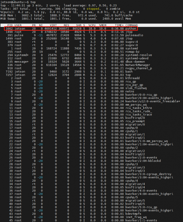
Press Ctrl+C to exit the view, then enter the command to end the process.
Kill -9 Python process PID
Enter: kill -9 1662 as shown in the figure above. This ends the running of the main program for that product. Note: After ending the running of the main program, the host device IP address: 5000 cannot be accessed successfully. However, the main program will still automatically run after the product is restarted. If you want the product not to run the main program automatically after powering on again, you can follow the content in the next section 1.2 Disable the main program from running automatically.
1.2 Disable the main program from running automatically
Every time the product is restarted, it will automatically run the main program by default. If you need to directly prohibit the product's main program from automatically running at startup, you need to cancel the main program configured by crontab to run automatically at startup. Enter the following command in the terminal:
crontab -e
If you are asked which editor to use, input 1 and then press Enter to choose nano.
When you open crontab's configuration file, you can see the following two lines:
@reboot sleep 3 && whoami && pulseaudio --start && sleep 2 && XDG_RUNTIME_DIR=/run/user/1000 ~/ugv_jetson/ugv-env/bin/python ~/ugv_jetson/app.py >> ~/ugv.log 2>&1
Add a # sign at the beginning of the line "...app.py >> ...." to comment out this line, as follows:
#@reboot sleep 3 && whoami && pulseaudio --start && sleep 2 && XDG_RUNTIME_DIR=/run/user/1000 ~/ugv_jetson/ugv-env/bin/python ~/ugv_jetson/app.py >> ~/ugv.log 2>&1In the terminal page, press Ctrl + X to exit. It will ask you Save modified buffer? Enter Y and press Enter to save the changes.
Enter the restart command to restart the device (the green light of the Raspberry Pi will flash during the restart process. When the green light flashes less frequently or goes out, it means the startup has been successful):
sudo reboot
You can still use jupyter Lab normally after the robot restarts (JupyterLab and the robot's main program app.py run independently of each other).
It should be noted here that because the lower device continues to communicate with the upper device through the serial port, the upper device may not be able to boot normally due to the continuous change of the serial port level during the restart process. Take the case where the host device is a Raspberry Pi. When restarting, the Raspberry Pi will not turn on again after shutting down. The red light is always on and the green light is not on. At this time, you can turn off the robot's power switch and turn it on again, and the robot will restart normally.
1.3 Start Docker remote service
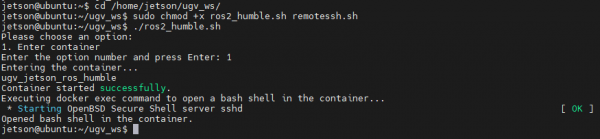
Go to the ugv_ws project directory in the Raspberry Pi and grant executable permissions to the ros2_humble.sh and remotessh.sh files:
cd /home/ws/ugv_ws
sudo chmod +x ros2_humble.sh remotessh.sh
Execute the script file ros2_humble.sh to start the Docker remote service:
./ros2_humble.sh
Enter 1 to enter the Docker container to start the SSH service.
1.4 Remote login to Docker container
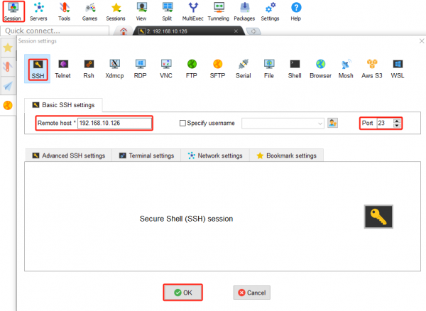
After the Docker container has successfully started the SSH service, use MobaXterm to remotely log in to the Docker container.
Click Session → SSH, the host IP is the Docker container IP, enter the IP address of the Jetson Orin Nano in Remote host, the Port is the assigned port 23, and finally click OK.
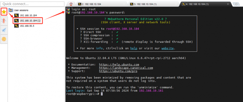
After the connection is established, enter the username: root and password: jetson. Note: It is normal for the screen to remain unchanged when entering the password, press enter to access the Docker container after the password is entered. The SSH remote connection to the Docker container has been successful since then.
2. Rviz View product model
By default, you have completed the main program and remotely connected to the Docker container according to the content in Chapter 1 UGV Rover Jetson Orin ROS2 1. Preparation.
2.1 View model joints
In the container, go to the workspace of the ROS 2 project for that product:
cd /home/ws/ugv_wsStart the Rviz2 model interface:
ros2 launch ugv_description display.launch.py use_rviz:=trueAt this time, you can only view the Rviz2 model interface of the product, but you cannot control the movement of the robot by sliding the slider on the control panel. Successfully start the terminal interface of the Rviz2 model. Do not close the interface, and then run the ROS2 robot driver node.
2.2 Run ROS2 robot driver node
We need to open a new Docker container terminal, click the ⭐ symbol in the left sidebar, double-click to open Docker's remote terminal, enter username: root, password: jetson.
In the container, go to the workspace of the ROS 2 project for that product:
cd /home/ws/ugv_wsRun the driver robot node, and there will be no information feedback after the node is finished running:
ros2 run ugv_bringup ugv_driver
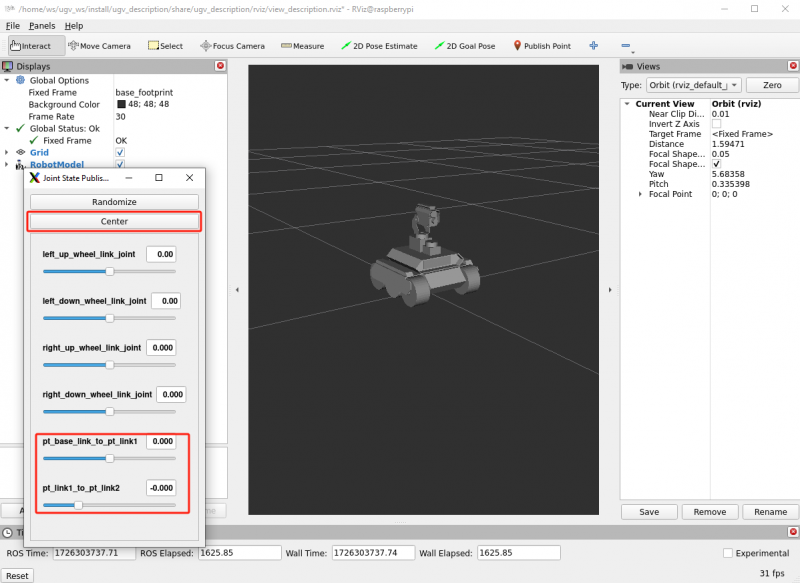
Then, you can control the pan-tilt rotation by sliding the slider on the control panel in the picture below, and both the model and the product will rotate with your slide.
- pt_base_link_to_pt_link1: Controls the rotation of the pan servo of the pan-tilt.
- pt_link1_to_pt_link2: Controls the rotation of the tilt servo of the pan-tilt.
- Center: Click this button and the pan-tilt will return to the center position.
2.3 Control robot lights
For UGV series products, the driver board integrates 12V switch control interfaces of 2 channels (the actual maximum voltage will change with the battery voltage), which are controlled by the IO4 and IO5 pins of ESP32 through MOS tubes. Each channel has two corresponding interfaces, a total of 4 12V switch control interfaces. According to the default assembly method, IO4 controls the chassis headlight (the light next to the OKA camera), and IO5 controls the headlight (the light on the USB camera pan-tilt). You can control the switching of these two switches and adjust the voltage level by sending the corresponding commands to the sub-controller. However, due to the inherent delay in MOSFET control, there may not be a linear relationship between the PWM output from the ESP32's IO and the actual voltage output.
For products without LEDs, you can expand the 12.6V withstand LED on these two 12V switches (in general, 12V withstand is also acceptable for safety and battery protection, the product's UPS will not charge the battery above 12V). You can also expand other peripherals on the remaining switch control interfaces, such as a 12V withstand water gun gearbox, which can be directly connected to the interface controlled by IO5 to achieve automatic aiming and shooting functionality.
Every time a control node runs, we need to open a new Docker container terminal, click the ⭐ symbol in the left sidebar, double-click to open Docker's remote terminal, enter username: root, password: jetson.
In the container, go to the workspace of the ROS 2 project for that product:
cd /home/ws/ugv_wsRun the light control node, and you can see that the three LED lights on the robot are lit up:
ros2 topic pub /ugv/led_ctrl std_msgs/msg/Float32MultiArray "{data: [255, 255]}" -1data: [0, 0]——The first 0 is the switch that controls the IO4 interface (chassis headlight); the second 0 is the switch that controls the IO5 interface (headlight).
The parameter variable range is 0-255. When the value of this variable is 0, the interface switches controlled by IO4 and IO5 are turned off; when this variable is 255, the voltage output by the interface switches controlled by IO4 and IO5 is close to the BAT voltage of the UPS (current UPS voltage of three lithium batteries connected in series).
Run the command to turn off the LED lights again, and you can see that all three LED lights are turned off:
ros2 topic pub /ugv/led_ctrl std_msgs/msg/Float32MultiArray "{data: [0, 0]}" -1This tutorial section has shown you how to view the product model joints, run the robot drive nodes, and control the robot lights, and then follow the following tutorial to learn about other ROS 2 controls.
3. Use Joystick or Keyboard Control
This section describes how to control movement using a joystick or keyboard keys. The product comes with an Xbox Bluetooth controller when shipped from the factory. By default, you have completed the main program and remotely connected to the Docker container according to the content in Chapter 1 UGV Rover Jetson Orin ROS2 1. Preparation.
3.1 Chassis drive
Before you can run the joystick control and keyboard control demos, you must first run the chassis drive node. In the previous section, we introduced the operation of one ROS2 robot drive node, and here we introduce the operation of another chassis drive node.
In the container, go to the workspace of the ROS 2 project for that product:
cd /home/ws/ugv_wsStart the robot driver node:
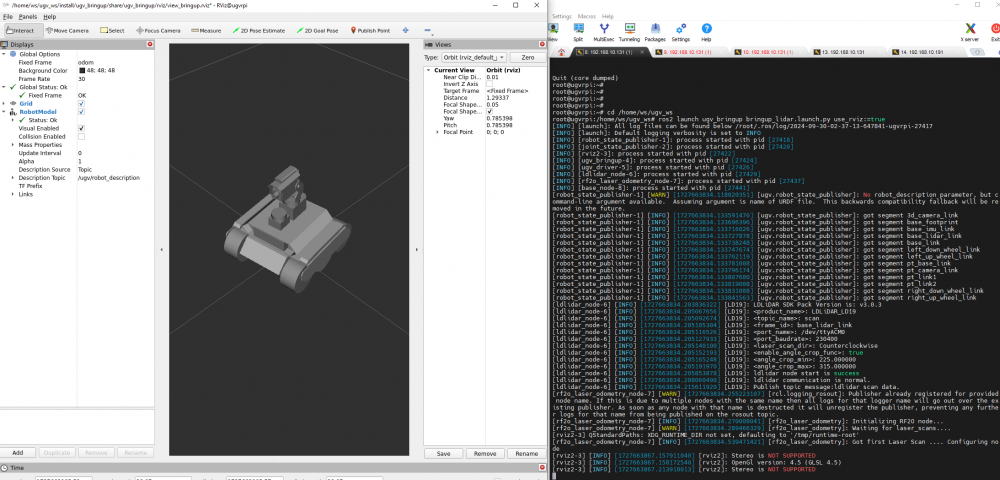
ros2 launch ugv_bringup bringup_lidar.launch.py use_rviz:=trueAt this moment, the robot pan-tilt will be turned to the center position, and the camera will face forward, and you can view the RVIZ2 model interface of the product. When the robot rotates in place, you can see that the model will also rotate with the robot.
Note: If the chassis of the UGV Rover 4WD and 6 wheels is not displayed in the model interface, you need to press Ctrl+C to turn off the running robot drive node first. Next, switch the UGV model in the ROS 2 project to the UGV Rover, enter the following command to switch the model, and then start the robot drive node.
export UGV_MODEL=ugv_rover
source ~/.bashrc
3.2 Joystick control
Start the robot driver node and connect the joystick receiver to the Jetson Orin Nano.
Once plugged in, you'll need to run the joystick control node on a new Docker container terminal first. Open a new Docker container terminal, click the "⭐" symbol in the left sidebar, double-click to open Docker's remote terminal, enter username: root, password: jetson.
In the container, first run the following command to check whether the joystick is recognized, as shown in the figure:
ls /dev/input

js0 represents the joystick here.
In the container, go to the workspace of the ROS 2 project for that product:
cd /home/ws/ugv_wsRun the joystick control node:
ros2 launch ugv_tools teleop_twist_joy.launch.py
Then turn on the switch on the back of the joystick, and you can control the movement of the robot when you see the red light on the joystick. Note: There are three function keys on the joystick: the key below R is used to lock or unlock, the left joystick -- forward or backward, the right joystick -- turn left or right.
You can close the joystick control node by pressing Ctrl+C.
3.3 Keyboard control
Close the joystick control node, and then run the joystick control node in the terminal window to run keyboard control node:
ros2 run ugv_tools keyboard_ctrl
Keep this window active (that is, make sure you are in the terminal window interface when operating the keys), and control the movement of the robot through the following keys:
| keyboard key | Operation description | keyboard key | Operation description | keyboard key | Operation description |
| Letter U | Left forward | Letter I | Straight ahead | Letter O | Right forward |
|---|---|---|---|---|---|
| Letter J | Turn left | Letter K | Stop | Letter L | Turn right |
| Letter M | Left backward | Symbol , | Straight backward | Symbol . | Right backward |
You can close the keyboard control node by pressing Ctrl+C.
4. Mapping Based on LiDAR
4.1 2D Mapping based on Gmapping
4.1.1 Gmapping introduction
Gmapping is a simultaneous positioning and mapping (SLAM) algorithm for robot navigation and map construction. It is based on the RBpf particle filter algorithm to help robots position themselves and build maps in unknown environments, which separates the positioning and mapping processes, first performing localization and then mapping.. The particle filter algorithm is an early mapping algorithm. Its basic principle is that the robot continuously obtains surrounding environment information through movement and observation, gradually reduces the uncertainty of its own position, and finally obtains accurate positioning results. Use the map and motion model of the previous moment to predict the pose at the current moment, then calculate the weights, resample, update the particle map, and so on.
Advantages of Gmapping:
- Indoor maps can be constructed in real time, and the amount of calculation required to construct small scene maps is small and the accuracy is high;
- Processes noise through particle filtering technology, which has strong robustness;
- Suitable for indoor robot navigation with a flat environment.
Disadvantages of Gmapping:
- Limited support for large-scale or highly dynamic environments. When building a large map, the amount of memory and calculation required will increase. It is not suitable for building large scene maps;
- There is no loop detection, so the map may be misaligned when the loop is closed. Although increasing the number of particles can close the map, it comes at the expense of increased calculations and memory.
- Gmapping is a 2D SLAM and cannot handle complex 3D scenes.
4.1.2 Start Gmapping mapping node
Before starting the mapping node, it is assumed that you have completed the main program and remotely connected to the Docker container according to the content in Chapter 1 UGV Rover Jetson Orin ROS2 1. Preparation.
In a new Docker container terminal, click the ⭐ symbol in the left sidebar, double-click to open Docker's remote terminal, enter username: root, password: jetson.
In the container, go to the workspace of the ROS 2 project for that product:
cd /home/ws/ugv_wsPlace the robot in the room where you need to build the map, and start the mapping node:
ros2 launch ugv_slam gmapping.launch.py use_rviz:=true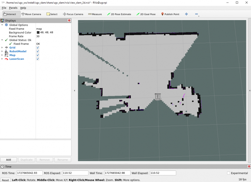
At this time, the map displayed on the RViz interface will only show the area scanned by the lidar. If there are still unscanned areas that need to be mapped, you can control the movement of the robot to scan and map.
In a new Docker container terminal, run either the joystick control or keyboard control node:
#Joystick control (make sure the joystick receiver is plugged into Jetson Orin Nano)
ros2 launch ugv_tools teleop_twist_joy.launch.py
#Keyboard control (keep the running keyboard control node active)
ros2 run ugv_tools keyboard_ctrl
In this way, you can control the movement of the chassis to realize the mapping of the surrounding environment.
When controlling the movement of the chassis, if the robot needs to be out of your sight for mapping, you can use the OAK camera to view the picture to control the movement of the robot to prevent the robot from moving and colliding after it is out of sight.
In a new Docker container terminal, enable the OAK camera:
ros2 launch ugv_vision oak_d_lite.launch.py
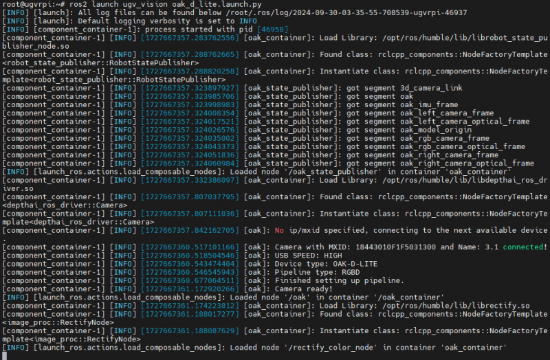
As shown in the figure, the OAK camera is successfully enabled.
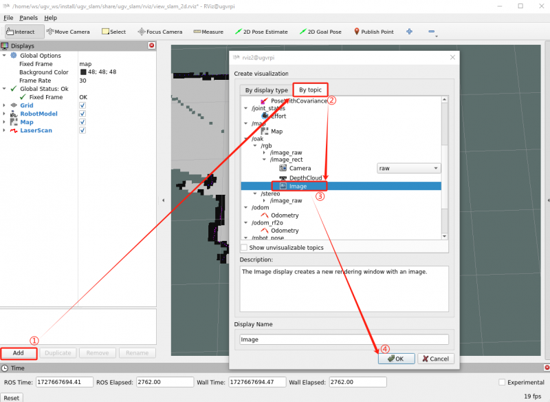
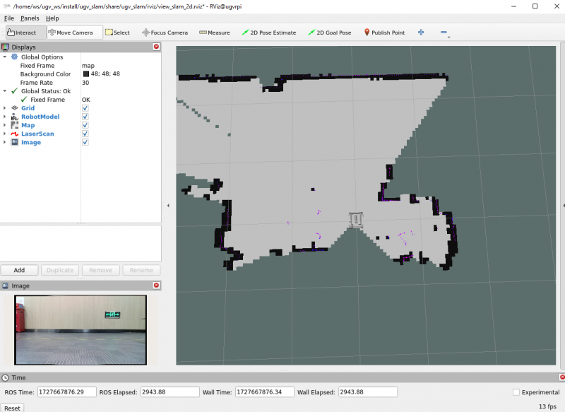
Then click Add in the lower left corner of the RViz interface, select By topic, find /oak, select the Image of /oak/rgb/image_rect, and click OK. Thus, you can see the OAK camera screen appearing in the interface in the lower left corner of RViz.
4.1.3 Save map
After the map is constructed, keep the mapping node running and save the map in a new Docker container terminal. Open a new Docker container terminal, click the ⭐ symbol in the left sidebar, double-click to open Docker's remote terminal, enter username: root, password: jetson.
In the container, go to the workspace of the ROS 2 project for that product:
cd /home/ws/ugv_wsAdd executable permissions to the map saving script:
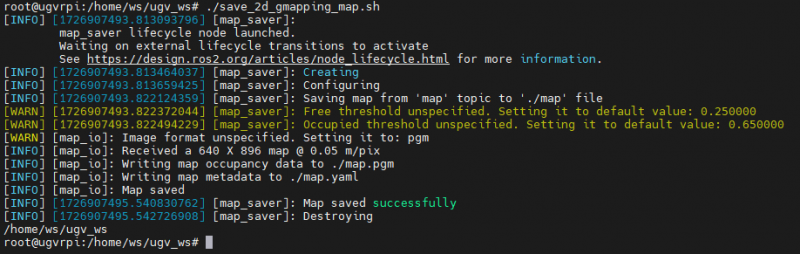
chmod +x ./save_2d_gmapping_map.sh
Then run the map saving script, as shown below, the map is saved successfully:
./save_2d_gmapping_map.sh
The details in this script are as follows:
cd /home/ws/ugv_ws/src/ugv_main/ugv_nav/maps
ros2 run nav2_map_server map_saver_cli -f ./map
After executing the above script file, a 2D raster map named map will be saved. The map is saved in the /home/ws/ugv_ws/src/ugv_main/ugv_nav/maps directory. You can see that two files are generated in the above directory, one is map.pgm and the other is map.yaml.
- map.pgm: This is a raster image of the map (usually a grayscale image file);
- map.yaml: This is the configuration file of the map.
Then the Gmapping mapping node can be closed via Ctrl+C.
4.2 2D Mapping based on Cartographer
4.2.1 Cartographer introduction
Cartographer is a set of SLAM algorithms based on graph optimization launched by Google. The main goal of the algorithm is to achieve real-time SLAM by computing resource consumption. It allows the robot to build a 2D or 3D map of the environment in real time, while tracking the robot's pose.
Advantages of Cartographer:
- High-precision mapping: Cartographer has high accuracy when processing 2D and 3D maps, especially in complex environments. Its accuracy mainly benefits from sensor combination and global optimization techniques, such as loop closure detection.
- Strong sensor combination capability: It can process data from multiple sensors at the same time, such as LiDAR, IMU (Inertial Measurement Unit), GPS, etc. By combining the data of different sensors, the accuracy of positioning and map construction can be improved.
- Global optimization: Through loop closure detection and global optimization, errors accumulated during long-term operation are effectively reduced, ensuring the overall consistency and accuracy of the map.
- Real-time: It can generate maps and track robot pose in real time while the robot is moving, and is suitable for real-time SLAM applications in dynamic environments.
Disadvantages of Cartographer:
- High computing resource consumption: High requirements on computing resources, especially when processing 3D SLAM. Its multi-sensor combination and global optimization algorithms require a lot of CPU and memory resources and may not be suitable for devices with low computing resources.
- Complex configuration: There are many configuration options, requiring users to deeply understand the meaning of each parameter and make fine adjustments to ensure optimal performance in a specific environment.
4.2.2 Start Cartographer mapping node
In the container, go to the workspace of the ROS 2 project for that product:
cd /home/ws/ugv_wsPlace the robot in the room where you need to build the map, and start the mapping node:
ros2 launch ugv_slam cartographer.launch.py use_rviz:=true
At this time, the map displayed on the RViz interface will only show the area scanned by the lidar. If there are still unscanned areas that need to be mapped, you can control the movement of the robot to scan and map.
In a new Docker container terminal, run either the joystick control or keyboard control node:
#Joystick control (make sure the joystick receiver is plugged into Jetson Orin Nano)
ros2 launch ugv_tools teleop_twist_joy.launch.py
#Keyboard control (keep the running keyboard control node active)
ros2 run ugv_tools keyboard_ctrl
In this way, you can control the movement of the chassis to realize the mapping of the surrounding environment.
When controlling the movement of the chassis, if the robot needs to be out of your sight for mapping, you can use the OAK camera to view the picture to control the movement of the robot to prevent the robot from moving and colliding after it is out of sight.
In a new Docker container terminal, enable the OAK camera:
ros2 launch ugv_vision oak_d_lite.launch.py
As shown in the figure, the OAK camera is successfully enabled.
Then click Add in the lower left corner of the RViz interface, select By topic, find /oak, select the Image of /oak/rgb/image_rect, and click OK. Thus, you can see the OAK camera screen appearing in the interface in the lower left corner of RViz.
4.2.3 Save map
After the map is constructed, keep the mapping node running and save the map in a new Docker container terminal. Open a new Docker container terminal, click the ⭐ symbol in the left sidebar, double-click to open Docker's remote terminal, enter username: root, password: jetson.
In the container, go to the workspace of the ROS 2 project for that product:
cd /home/ws/ugv_wsAdd executable permissions to the map saving script:
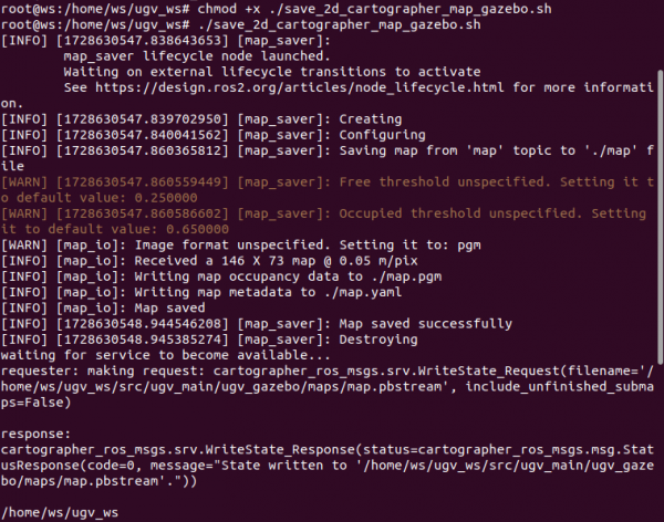
chmod +x ./save_2d_cartographer_map.sh
Then run the map saving script, as shown below, the map is saved successfully:
./save_2d_cartographer_map.sh
The details in this script are as follows:
cd /home/ws/ugv_ws/src/ugv_main/ugv_nav/maps
ros2 run nav2_map_server map_saver_cli -f ./map && ros2 service call /write_state cartographer_ros_msgs/srv/WriteState "{filename:'/home/ws/ugv_ws/src/ugv_main/ugv_nav/maps/map.pbstream'}"
After executing the above script file, a map named map will be saved. The map is saved in /home/ws/ugv_ws/src/ugv_main/ugv_nav/maps. You can see three files generated in this directory, which are map.pgm, map.yaml, and map.pbstram.
Note: If you have used Gmapping to create a map before, the map created here will overwrite the one created previously. If you want to build a different map, you can change the name of the map you created. Just change the map in ./map section of the save2d_cartographer script to the name of the map you want to build.

For example: if you need to create a map named room, change the second line of instructions in the script to
ros2 run nav2_map_server map_saver_cli -f ./room && ros2 service call /write_state cartographer_ros_msgs/srv/WriteState "{filename:'/home/ws/ugv_ws/src/ugv_main/ugv_nav/maps/room.pbstream'}"
5. 3D Mapping Based on Depth Camera
This tutorial will show you how to use the RTAB-Map algorithm to perform 3D mapping based on LiDAR and depth camera. We provide two visualization approaches for mapping. Before starting the mapping node, it is assumed that you have completed the main program and remotely connected to the Docker container according to the content in Chapter 1 UGV Rover Jetson Orin ROS2 1. Preparation.
5.1 Visualizing in RTAB-Map
RTAB-Map (Real-Time Appearance-Based Mapping) is an open source algorithm for Simultaneous Localization and Mapping (SLAM), which is widely used in robot navigation, autonomous vehicles, drones and other fields. It uses data from visual and lidar sensors to build an environment map and perform positioning. It is a SLAM method based on loop closure detection.
Start the visualization node of RTAB-Map:
ros2 launch ugv_slam rtabmap_rgbd.launch.py use_rviz:=falseIn a new Docker container terminal, run either the joystick control or keyboard control node:
#Joystick control (make sure the joystick receiver is plugged into Jetson Orin Nano)
ros2 launch ugv_tools teleop_twist_joy.launch.py
#Keyboard control (keep the running keyboard control node active)
ros2 run ugv_tools keyboard_ctrl
In this way, you can control the movement of the chassis to realize the mapping of the surrounding environment. After the mapping is completed, press Ctrl+C to exit the mapping node, and the system will automatically save the map. The default saving path of the map is ~/.ros/rtabmap.db.
5.2 Visualizing in RViz
Start the visualization node of RTAB-Map:
ros2 launch ugv_slam rtabmap_rgbd.launch.py use_rviz:=trueIn a new Docker container terminal, run either the joystick control or keyboard control node:
#Joystick control (make sure the joystick receiver is plugged into Jetson Orin Nano)
ros2 launch ugv_tools teleop_twist_joy.launch.py
#Keyboard control (keep the running keyboard control node active)
ros2 run ugv_tools keyboard_ctrl
In this way, you can control the movement of the chassis to realize the mapping of the surrounding environment. After the mapping is completed, press Ctrl+C to exit the mapping node, and the system will automatically save the map. The default saving path of the map is ~/.ros/rtabmap.db.
Before starting navigation, first make sure you have built an environment map named map. If you have not followed the previous tutorial, you need to follow UGV Rover PI ROS2 4. 2D Mapping Based on LiDAR or UGV Rover PI ROS2 5. 3D Mapping Based on Depth Camera to create a map.
After the mapping is completed, then start the navigation, we provide a variety of autonomous navigation modes, you can choose one of the following autonomous navigation modes for robot navigation.
1. AMCL algorithm
Adaptive Monte Carlo Localization (AMCL) is a particle filter-based positioning algorithm in ROS 2 that uses 2D lidar to estimate the position and direction (i.e. posture) of the robot in a given known map. AMCL is mainly used for mobile robot navigation. It matches existing maps with laser sensors (such as lidar) to calculate the robot's position and direction in the map. The core idea is to represent the possible position of the robot through a large number of particles, and gradually update these particles to reduce the uncertainty of the robot's pose.
Advantages of AMCL:
- Adaptive particle number: AMCL will dynamically adjust the number of particles based on the uncertainty of the robot's position.
- Suitable for dynamic environments: While AMCL assumes a static environment, it can handle a small number of dynamic obstacles, such as pedestrians and other moving objects, to a certain extent, which makes it more flexible in practical applications.
- Reliable positioning capability: AMCL's positioning effect in known maps is very reliable. Even if the robot's pose is initially uncertain, it can gradually converge to the correct pose.
AMCL assumes that the map is known and you cannot create the map yourself. It also relies on high-quality static maps that are matched to sensor data. If there is a big difference between the map and the real environment, the positioning effect will be affected. AMCL is often used for autonomous navigation of mobile robots. During the navigation process, the robot can determine its own pose through AMCL and rely on known maps for path planning and obstacle avoidance.
In the container, start navigation based on the AMCL algorithm. After successful startup, you can see the RViz screen of the previously built map:
ros2 launch ugv_nav nav.launch.py use_localization:=amcl use_rviz:=trueThen, you can determine the initial position of the robot based on 6.2 Initialize the robot's position.
2. EMCL algorithm
EMCL is an alternative Monte Carlo localization (MCL) package to AMCL. Unlike AMCL, KLD sampling and adaptive MCL are not implemented. Instead, extended resets and other features are implemented. EMCL does not rely entirely on adaptive particle filtering, but introduces methods such as extended reset to improve positioning performance. EMCL implements the extended reset strategy, a technique for improving the quality of particle sets to better handle uncertainty and drift in positioning.
Start the navigation based on the EMCL algorithm. After successful startup, you can see the RViz screen of the previously built map:
ros2 launch ugv_nav nav.launch.py use_localization:=emcl use_rviz:=trueThen, you can determine the initial position of the robot based on 6.2 Initialize the robot's position.
6.1.1.2 Pure positioning based on Cartographer
Cartographer is an open-source Google system that provides real-time simultaneous localization and mapping (SLAM) in 2D and 3D across multiple platforms and sensor configurations.
Cartographer system architecture overview: You can see that the optional inputs on the left include depth information, odometer information, IMU data, and fixed Frame attitude.
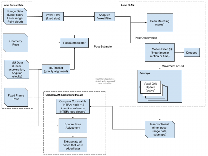
For more tutorials, please refer to official document and project address.
Start pure positioning based on Cartographer. After successful startup, you can see the RViz screen of the previously built map:
Note: The navigation mode based on Cartographer's pure positioning can only be used after using Cartographer to build the map.
ros2 launch ugv_nav nav.launch.py use_localization:=cartographer use_rviz:=trueThen, you can determine the initial position of the robot based on 6.2 Initialize the robot's position.
6.1.1.3 Based on DWA and TEB algorithms
1. DWA algorithm Dynamic Window Approaches (DWA) is a suboptimal method based on predictive control theory, because it can safely and effectively avoid obstacles in an unknown environment, and has the characteristics of small computational effort, rapid response and strong operability. The DWA algorithm is a local path planning algorithm.
The core idea of this algorithm is to determine a sampling speed space that satisfies the mobile robot's hardware constraints in the speed space (v, ω) based on the current position and speed status of the mobile robot, and then calculate the trajectories of the mobile robot within a certain period of time under these speed conditions. trajectory, and evaluate the trajectories through the evaluation function, and finally select the speed corresponding to the trajectory with the best evaluation as the movement speed of the mobile robot. This cycle continues until the mobile robot reaches the target point.
Start the navigation based on the DWA algorithm. After successful startup, you can see the RViz screen of the previously built map:
ros2 launch ugv_nav nav.launch.py use_localplan:=dwa use_rviz:=trueThen, you can determine the initial position of the robot based on 6.2 Initialize the robot's position.
2. TEB algorithm
TEB stands for Time Elastic Band Local Planner. This method performs subsequent corrections on the initial global trajectory generated by the global path planner to optimize the robot's motion trajectory and belongs to local path planning. During the trajectory optimization process, the algorithm has a variety of optimization objectives, including but not limited to: overall path length, trajectory running time, distance from obstacles, passing intermediate way points, and compliance with robot dynamics, kinematics, and geometric constraints.
Start the navigation based on the TEB algorithm. After successful startup, you can see the RViz screen of the previously built map:
ros2 launch ugv_nav nav.launch.py use_localplan:=teb use_rviz:=trueThen, you can determine the initial position of the robot based on 6.2 Initialize the robot's position.
The map navigation mode introduced above is based on the 2D construction of LiDAR. For the 3D map built according to UGV Rover PI ROS2 5. Mapping Based on Depth Camera, please refer to the navigation startup method in this subsection.
Enable nav positioning:
ros2 launch ugv_nav rtabmap_localization_launch.py
You need to wait for the 3D data to be loaded, wait for a period of time, and then you can start navigation as shown in the figure below.
In a new terminal, turn on navigation and choose one of the two navigation modes:
- DWA algorithm
ros2 launch ugv_nav rtabmap_localization_launch.py
- TEB algorithm
ros2 launch ugv_nav nav_rtabmap.launch.py use_localplan:=teb use_rviz:=trueChoose a navigation mode based on the map created above to start the navigation, then proceed with the following content.
6.2 Initialize the robot's position
By default, when navigation is started, the robot initially has no idea where it is and the map waits for you to provide it with an approximate starting location.
First, find the robot's location on the map and check the actual location of your robot. Manually set the robot's initial pose in RViz. Click the 2D Pose Estimate button and indicate the robot's location on the map. The direction of the green arrow is the direction the robot pan-tilt is facing forward.
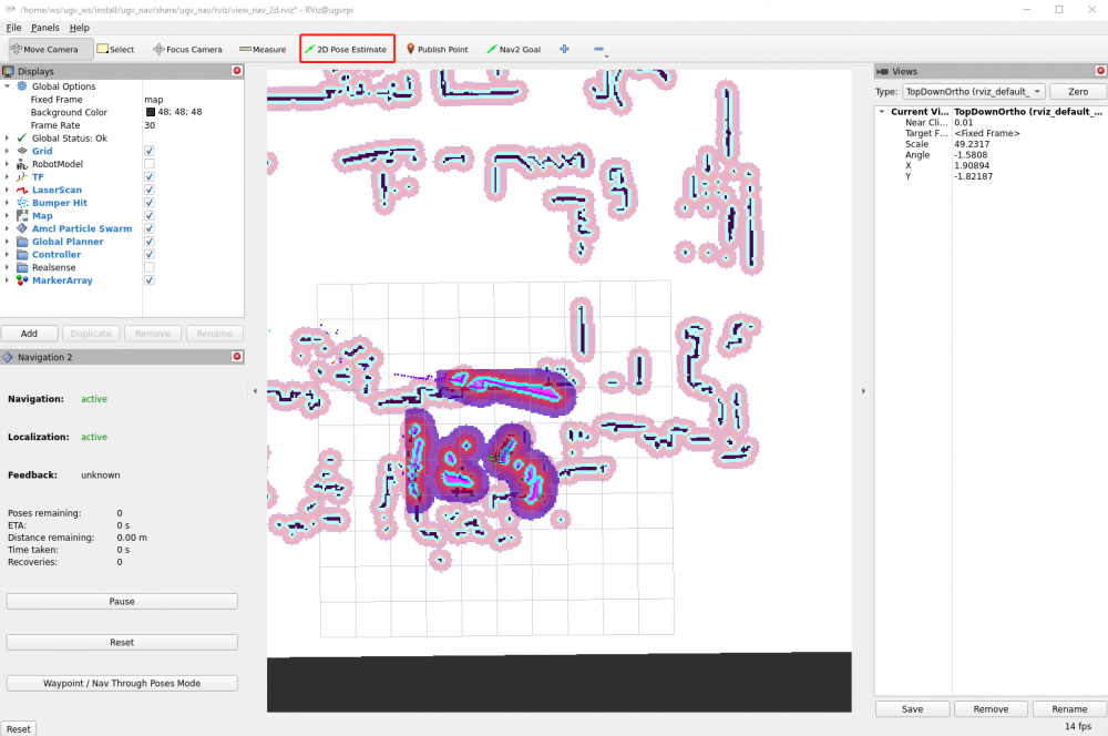
Keep the operation of the navigation terminal, set the approximate initial pose of the robot, and ensure that the navigation ensures that the actual position of the robot is roughly corresponding to the ground. You can also control the robot through the keyboard on a new terminal to simply move and rotate it to assist in initial positioning.
ros2 run ugv_tools keyboard_ctrl
6.3 Send target pose
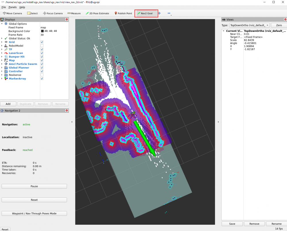
Select a target location for the robot on the map. You can use the Nav2 Goal tool to send the target location and direction to the robot. Indicate the location (target point) that the robot wants to navigate to automatically on the RViz map. The direction of the green arrow is the direction the robot pan-tilt is facing forward.
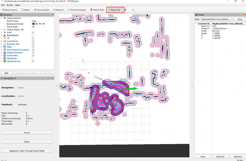
Once the target pose is set, the navigation will find the global path and begin navigating to move the robot to the target pose on the map. Now you can see the robot moving towards the actual target location.
In the lower left corner of the RViz interface, there is a Nav2 RViz2 plug-in [Waypoint/Nav Through Poses Mode], which can switch the navigation mode. Click the [Waypoint/Nav Through Poses Mode] button to switch to the multi-point navigation mode.
Then use Nav2 Goal in the RViz2 toolbar to give multiple target points to move. After setting, click [Start Waypoint Following] in the lower left corner to start path planning navigation. The robot will move according to the order of the selected target points. After reaching the first target point, it will automatically go to the next target point without any further operation. The robot will stop if it reaches the last target point.
6.4 Change map name
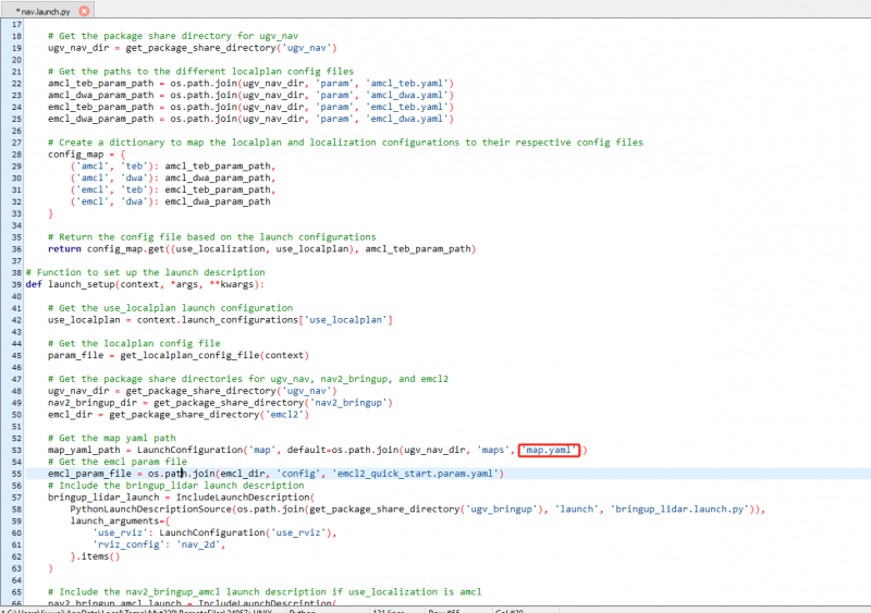
According to the UGV Rover PI ROS2 4. 2D Mapping Based on LiDAR tutorial, the default names of the maps we build are map, so the maps called by the above files that start navigation are also map. However, if you change the name of the map when building the map, you need to synchronously change the name of the map called in the startup file before starting navigation.
Open the nav.launch.py script file in the directory /home/ws/ugv_ws/src/ugv_main/ugv_nav/launch. Change map.yaml to the name of the map you saved as shown below. Save and close after making changes.
Then recompile the nav package, enter the product workspace in the Docker container terminal to compile the ugv_nav package:
cd /home/ws/ugv_ws
colcon build --packages-select ugv_nav --symlink-install
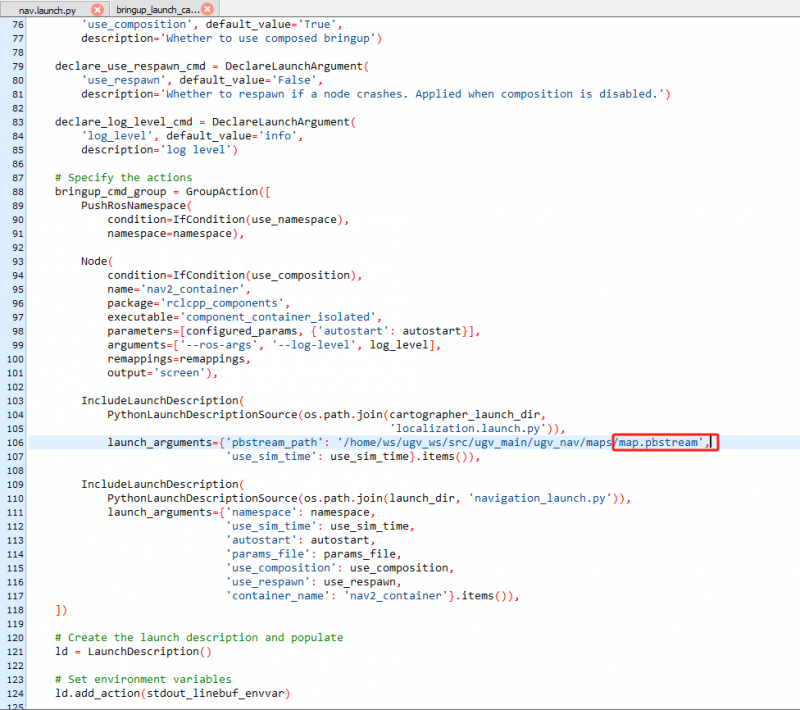
source ~/.bashrcIf you change the name of the saved map when you use Cartographer to create a map, in addition to the above files, you also need to change the bringup_launch_cartographer.launch.py script file in the /home/ws/ugv_ws/src/ugv_main/ugv_nav/launch/nav_bringup/ directory. Change map.pbstream to the name of the map you saved as shown below. Save and close after making changes, then recompile the ugv_nav package again.
This tutorial explains how to use Nav2 with SLAM. The following steps show you how to generate an occupancy raster map and move the robot using Nav2. By default, you have completed the main program and remotely connected to the Docker container according to the content in Chapter 1 UGV Rover PI ROS2 1. Preparation.
In a Docker container, start the robot's RViz interface and navigation:
ros2 luanch ugv_nav slam_nav.launch.py use_rviz:=true7.1 Manual exploration
In the RViz interface, you can manually post navigation points for exploration. You can use the Nav2 Goal tool to send the target location and direction to the robot. In the RViz interface, indicate the location (target point) that the robot wants to explore, and the direction of the green arrow is the direction that the robot pan-tilt is facing forward.
Similarly, you can also use the keyboard or joystick to explore remotely. In a new Docker container terminal, run either joystick control or keyboard control node. For details, please refer to UGV Rover PI ROS2 3. Use Joystick or Keyboard Control Chapter:
#Joystick control (make sure the joystick receiver is plugged into Jetson Orin Nano)
ros2 launch ugv_tools teleop_twist_joy.launch.py
#Keyboard control (keep the running keyboard control node active)
ros2 run ugv_tools keyboard_ctrl
Alternatively, you can control the robot movement through the web for exploration, please refer to the UGV Rover PI ROS2 9. Web Control Tool Chapter.
In this way, you can control the movement of the chassis to explore the surrounding environment. As you control the movement of the chassis, the map that the robot has moved will gradually be displayed in the RViz interface.
7.2 Automatic exploration
In addition to manual exploration, you can also directly let the robot explore the map automatically. Note: Automatic exploration needs to be carried out in a closed area. It is generally recommended to conduct automatic exploration in a closed small room, or in the Gazebo simulation map. For details, please refer to UGV Rover PI ROS2 11. Gazebo Simulation Debugging.
Keep the robot and navigation instructions running on RViz interface, and then run the automatic exploration instructions in a new Docker container:
ros2 launch explore_lite explore.launch.py
The robot will move and explore within the enclosed area, and the explored area will also be displayed on the RViz interface.
7.3 Save map
After navigation and exploration, you can save the map in a new Docker container terminal. Open a new Docker container terminal, click the ⭐ symbol in the left sidebar, double-click to open Docker's remote terminal, enter username: root, password: jetson.
In the container, go to the workspace of the ROS 2 project for that product:
cd /home/ws/ugv_wsAdd executable permissions to the map saving script:
chmod +x ./save_2d_gmapping_map.sh
Then run the map saving script, as shown below, the map is saved successfully:
./save_2d_gmapping_map.sh
The details in this script are as follows:
cd /home/ws/ugv_ws/src/ugv_main/ugv_nav/maps
ros2 run nav2_map_server map_saver_cli -f ./map
After executing the above script file, a 2D raster map named map will be saved. The map is saved in the /home/ws/ugv_ws/src/ugv_main/ugv_nav/maps directory. You can see that two files are generated in the above directory, one is map.pgm and the other is map.yaml.
- map.pgm: This is a raster image of the map (usually a grayscale image file);
- map.yaml: This is the configuration file of the map.
8. Web Natural Language Interaction
This tutorial will introduce how to directly control the robot using natural language on the web page. In this tutorial, we use the Ollama command-line tool to run a large language model, enter the corresponding commands through the command line to use the Gemma model to generate JSON instructions, and send the generated JSON instructions to the robot, which supports the robot to perform tasks such as basic movement, assisted mapping, and navigation.
8.1 Ollama introduction
Ollama is an open source large language model service tool that simplifies running large language models locally and lowers the threshold for using large language models. It also provides a rich pre-built model library, including Qwen2, Llama3, Phi3, Gemma2 and other large-scale language models that are open source and can be easily integrated into various applications. Ollama's goal is to make it easy to deploy and interact with large language models, both for developers and end users.
8.2 Install and configure Ollama
1. Click Ollama official website to download the Ollama installation package. Ollama officially supports downloading for different operating systems. According to your operating system, select the corresponding installation package to download. In this tutorial, it is installed on the Windows operating system. After the download is complete, run the installation package and follow the prompts to complete the installation process.
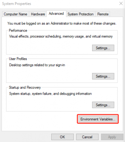
2. After the installation is completed, you need to configure the Windows system environment variables. In the Start menu bar, search for Advanced system settings and select Environment variables in the system settings.
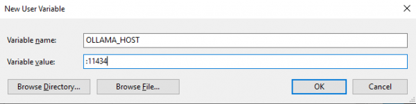
3. Select New in user variables, fill in the variable name OLLAMA_HOST and variable value :11434, as shown below. Click OK to save after filling in.
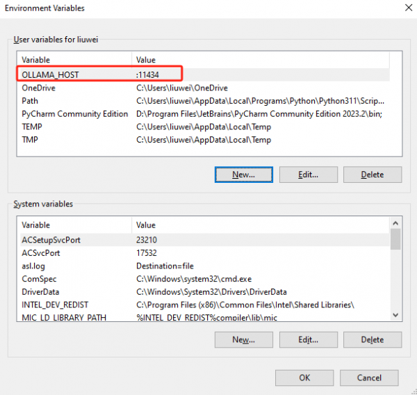
4. As shown in the figure below, the addition is successful. Finally, click OK to save the environment variable configuration.
8.3 Download large model to local
Ollama supports a range of models available at Ollama Model Library, below are some example models that can be downloaded, the Gemma2:9B model is used in this tutorial.
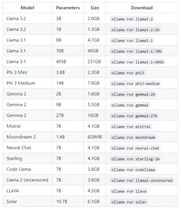
NOTE: You should have at least 8GB RAM to run a 7B model, 16GB RAM to run a 13B model, and 32GB RAM to run a 33B model. We use the Gemma2:9B model in our tutorial, so you need to ensure that your computer's RAM is 16GB or above.
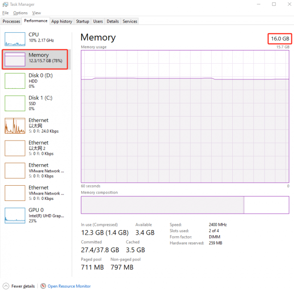
1. First, make sure your computer’s RAM is 16 GB or above. Search for Task Manager in the Start menu bar, select Memory and check if the memory size is 16GB or above.
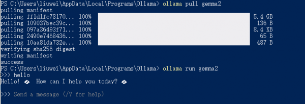
2. Then in Windows system, press Ctrl+R and enter cmd to open the terminal, and use the pull command to completely download the large model from the Ollama remote repository to the local computer.
ollama pull gemma2
3. Once the download is complete, you can run a large model for testing, and randomly test the conversation with AI.
ollama run gemma2
8.4 Change IP address
First, determine what the local IP address you are using for your Ollama deployment and remember that IP address.
- Windows system
Press Ctrl+R, enter cmd to open the terminal, and enter the command to view the IP address in the terminal:
ipconfig
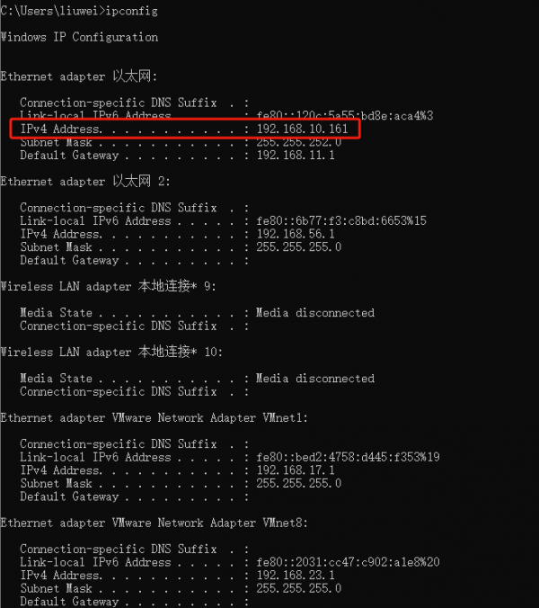
Remember this IP address, and then in the Jetson Orin Nano operating system, open the app.py file in the /home/ws/ugv_ws/src/ugv_main/ugv_chat_ai/ugv_chat_ai/ directory, as shown below, and change the IP address before line 85 ":11434" to the local IP address you got earlier.
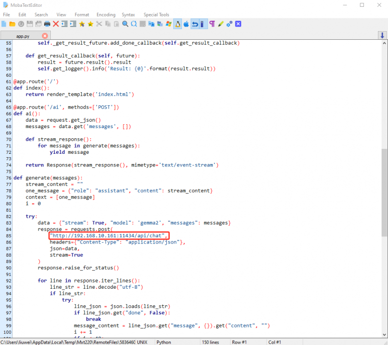
Press Ctrl+S to save and exit after modification.
8.5 Chassis drive
Before starting the chassis driver, by default you have completed the main program and remotely connected to the Docker container according to the content in Chapter 1 UGV Rover PI ROS2 1. Preparation.
In the container, go to the workspace of the ROS 2 project for that product:
cd /home/ws/ugv_wsStart the robot driver node:
ros2 launch ugv_bringup bringup_lidar.launch.py use_rviz:=trueAt this moment, the robot pan-tilt will be turned to the center position, and the camera will face forward, and you can view the RVIZ2 model interface of the product. When the robot rotates in place, you can see that the model will also rotate with the robot.
8.6 Launch Web AI application
Open a new Docker container terminal, click the "⭐" symbol in the left sidebar, double-click to open Docker's remote terminal, enter username: root, password: jetson.
Run the web-side AI application:
ros2 run ugv_chat_ai app
After successful operation, it will appear as shown below:

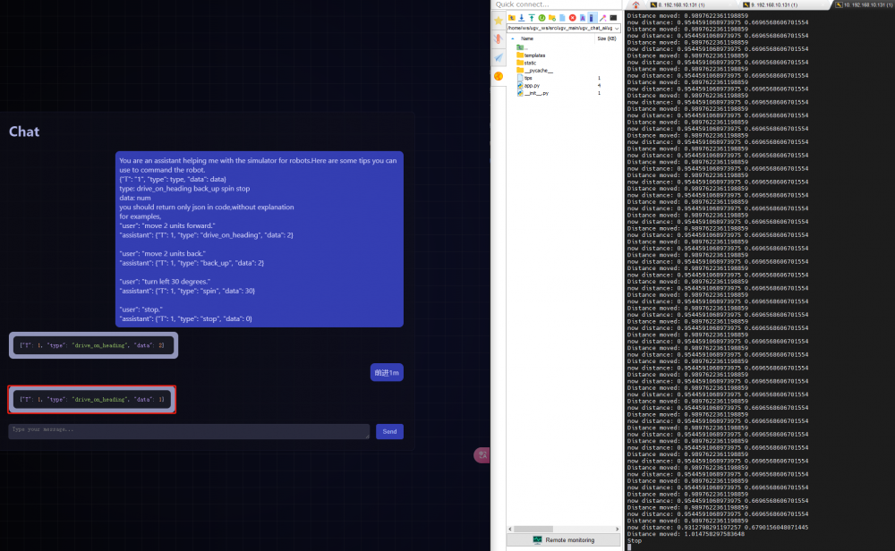
Then, in the browser of the operating system where Ollama is deployed, visit the IP Address: 5000 to enter the interface of the AI application. As shown in the picture above, the URL visited here is 192.168.10.131:5000.
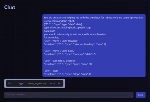
In the chat interface with AI, we need to send some prompts to AI first, so that AI can feedback JSON instructions to control the robot's movement. Here are the tips we provide, which can be copied and sent directly to AI:
You are an assistant helping me with the simulator for robots.Here are some tips you can use to command the robot.
{"T": "1", "type": type, "data": data}
type: drive_on_heading back_up spin stop
data: num
you should return only json in code,without explanation
for examples,
"user": "move 2 units forward."
"assistant": {"T": 1, "type": "drive_on_heading", "data": 2}

"user": "move 2 units back."
"assistant": {"T": 1, "type": "back_up", "data": 2}

"user": "turn left 30 degrees."
"assistant": {"T": 1, "type": "spin", "data": 30}

"user": "stop."
"assistant": {"T": 1, "type": "stop", "data": 0}
Wait for about 1 minute, and the AI will feedback the JSON instruction to move 2m straight, as shown below:
- type: The types of robot movement. driver_on_heading: move forward; back_up: move backward; spin: rotate; stop: stop.
- data: The numerical parameters of robot movement. When moving forward or backward, the unit is m; when rotating, the unit is degrees.
Next, you need to start the relevant interface for robot movement. After the AI feeds back the JSON command, the actual robot will move accordingly. Open a new Docker container terminal and run the following command:
ros2 run ugv_tools behavior_ctrl
After the operation is completed, there will be no feedback before the robot is given motion instructions.
Example: Let the robot move forward 1m. The AI application will feedback a JSON command to move forward 1m. The ros2 run ugv_tools behavior_ctrl command will feedback parameters such as the robot's movement distance and current distance. The robot will stop after completing the 1m movement.
9. Web Control Tool
This chapter introduces web-based console tools. The robot project uses the Vizanti Web tool, a web-based visualization and control tool designed to make it easier to operate the robot's ROS2 functions. The application tries to replicate the orthographic 2D view of RViz on the browser as precisely as possible. The second objective is to allow reconfiguration, planning and execution of movement and task instructions such as target points and waypoints via custom buttons and parameters.
By default, you have completed the main program and remotely connected to the Docker container according to the content in Chapter 1 UGV Rover PI ROS2 1. Preparation. In the container, start the web application, ip is the IP address of the Jetson Orin (also the IP address used to log in to the Docker container):
ros2 launch ugv_web_app bringup.launch.py host:=ip
After successful operation, it will appear as shown below:
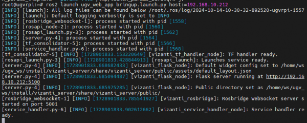
Then in a computer from the same LAN (it can also be Jetson Orin system), open a browser (preferably Google Chrome) and enter Jetson Orin's IP address + :5100 in the address bar, for example :192.168.10.212:5100.
At this point, there is no data displayed in the web interface because there is no relevant node to start the robot.
9.1 Control robot movement
9.1.1 Run robot driver node
Open a new Docker container terminal, click the ⭐ symbol in the left sidebar, double-click to open Docker's remote terminal, enter username: root, password: jetson.
Start the robot driver node:
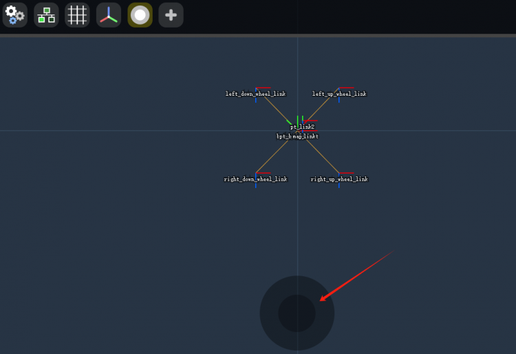
ros2 launch ugv_bringup bringup_lidar.launch.py use_rviz:=trueOnce launched, a TF coordinate system diagram appears in the web interface, as well as the RViz 2 model interface for the robot.
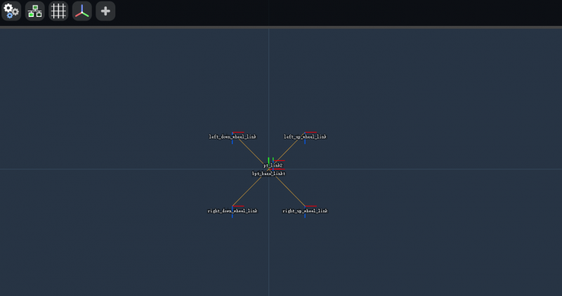
The following describes common tools for Web interfaces:
 Global Settings: Global settings. You can set the background color and fix the TF coordinate system, and you can reset the camera view to zero and default zoom.
 Rosbridge Connection: Bridge connection. Here shows information such as the connection status and the URL link.
 Grid Renderer: Grid. It shows adjustable metric grid.
 TF Frame Renderer: TF coordinate system. Render the TF coordinate system, most of the options are the same as in RViz, and you don't need to set them anymore.
 Add Widgets: Add widgets.
9.1.2 Control robot movement
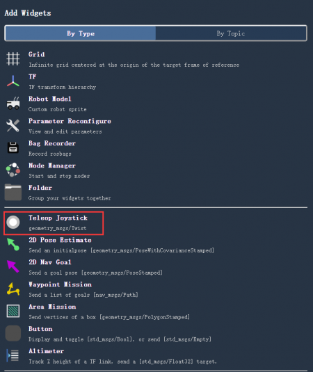
Next, we first add a joystick widget to control the movement of the robot. Click Add Widgets and select Teleop Joystick, a circle button will appear in the web interface, through which you can control the movement of the robot.
9.2 Map
Before starting the mapping node, make sure that the above-mentioned chassis drive node is shut down. You need to refer to UGV Rover PI ROS2 4. 2D Mapping Based on LiDAR or UGV Rover PI ROS2 5. 3D Mapping Based on Depth Camera to start the mapping node.
Once launched, click Add Widgets in the web interface and select Map.
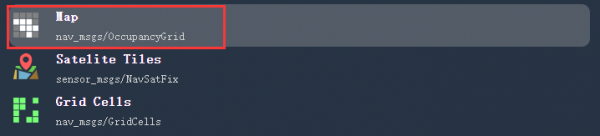
Next, click the Map icon and select Topic as /map, so that you can see the map in the RViz interface.
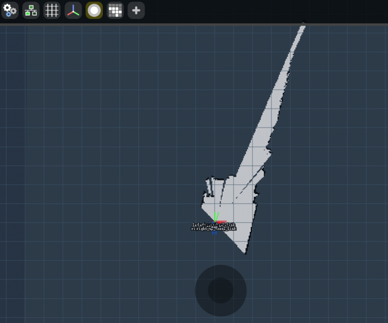
Finally, you can use the joystick or keyboard to control the movement of the robot to build a map, or you can use the joystick widget added earlier to control the movement of the robot to build a map. After building the map, you can also refer to the instructions in the mapping tutorial to save the map.
Once you've built the map, run the command to start navigation in the Docker container:
ros2 launch ugv_nav nav.launch.py use_rviz:=trueThere is no use_localization specified in this command, and the navigation based on the AMCL algorithm is used by default, as detailed in UGV Rover PI ROS2 6. Auto Navigation section.
By setting the Topic in the Map widget to /map, you can see the map saved after completing the previous mapping, which is consistent with the map displayed in the RViz2 interface.
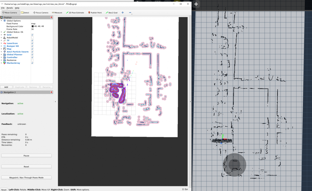
Click Add Widgets in the web interface and select the two widgets 2D Pose Estimate and 2D Nav Goal to add.
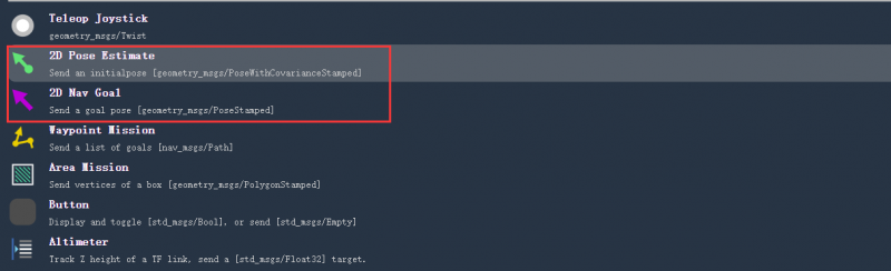
You can use 2D Pose Estimate to indicate the position of the robot on the map. The direction of the green arrow is the direction in which the robot's pan-tilt is facing forward.
Select a target location for the robot on the map. You can use the 2D Nav Goal tool to send the target location and direction to the robot. Indicate the location (target point) that the robot wants to automatically navigate to on a map in the web interface, and the direction of the purple arrow is the direction of the robot pan tilt facing forward. Release the mouse after pointing out the target location, and the robot will move to that target location.
From now on, you can control robot movement, mapping and navigation through web control tools. Users can also expand and develop the functions of other components according to their own needs.
10. Command interaction
This tutorial shows you how to use commands to control the robot for basic movement and to move the robot to a navigation point. Before starting this tutorial, by default you have completed the main program and remotely connected to the Docker container according to the content in Chapter 1 UGV Rover PI ROS2 1. Preparation.
First, start the robot behavior control interface in the container and keep this command running:
ros2 run ugv_tools behavior_ctrl
10.1 Basic control
Before performing basic control, you must first ensure that the robot is placed on the ground. The robot needs to judge whether the distance traveled by the robot has completed the goal based on the odometer.
Next open a new Docker container terminal, click the 《Star》 symbol in the left sidebar, double-click to open Docker's remote terminal, enter username: root, password: jetson.
In the container, go to the workspace of the ROS 2 project for that product:
cd /home/ws/ugv_wsStart the car driver node and keep this command running:
ros2 launch ugv_bringup bringup_lidar.launch.py use_rviz:=trueAt this moment, the robot pan-tilt will be turned to the center position, and the camera will face forward, and you can view the RVIZ2 model interface of the product. When you rotate the car manually, you can see that the model will also rotate along with it.
10.1.1 Move forward
Then in a new Docker container, send the action target of the robot's moving forward, and data is the distance the robot travels, in meters:
ros2 action send_goal /behavior ugv_interface/action/Behavior "{command: '[{\"T\": 1, \"type\": \"drive_on_heading\", \"data\": 0.5}]'}"At this time, the robot will advance the distance set by data in the command, and you can see that the model in the Rviz2 model interface of the product will also move forward together.
10.1.2 Move backward
Send the action target of the robot's moving backward, and data is the distance the robot travels, in meters:
ros2 action send_goal /behavior ugv_interface/action/Behavior "{command: '[{\"T\": 1, \"type\": \"back_up\", \"data\": 0.5}]'}"At this time, the robot will retreat the set distance, and you can see that the model in the Rviz2 model interface of the product will also move backward together.
10.1.3 Rotate
Send the action target of the robot rotation (the unit of data is degrees, positive number means to turn left, negative number means to turn right):
ros2 action send_goal /behavior ugv_interface/action/Behavior "{command: '[{\"T\": 1, \"type\": \"spin\", \"data\": -50}]'}"At this time, the robot will rotate to the set angle, and you can see that the model in the Rviz2 model interface of the product will also rotate along with it.
10.1.4 Stop
Send the action target of the robot to stop:
ros2 action send_goal /behavior ugv_interface/action/Behavior "{command: '[{\"T\": 1, \"type\": \"stop\", \"data\": 0}]'}"At this time, the robot will stop moving, and you can see that the model in the Rviz2 model interface of the product will also stop moving. Normally, the robot will stop moving after the value of the given data parameter is finished.
10.2 Get current point location
Before interacting with the following tutorial commands, you need to enable navigation first. Before enabling navigation, make sure you have built an environment map. If you have not followed the previous tutorial, you first need to follow UGV Rover PI ROS2 4. 2D Mapping Based on LiDAR or UGV Rover PI ROS2 5. 3D Mapping Based on Depth Camera to create a map.
After the map construction is completed, place the robot at the actual location of the map. The robot needs to judge whether it has completed the movement to the target location based on the odometer, and run the command to start navigation in a new container:
ros2 launch ugv_nav nav.launch.py use_rviz:=trueThere is no use_localization specified in this command, and the navigation based on the AMCL algorithm is used by default, as detailed in UGV Rover PI ROS2 6. Auto Navigationsection.
You can save several target positions as navigation points before using commands to control the robot to move to navigation points. First get the current point location information:
ros2 topic echo /robot_pose --once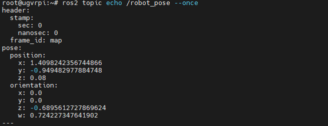
Save the location information obtained previously as a navigation point, in the following command, data is the name of the navigation point, which can be set to any letter between a~g:
ros2 action send_goal /behavior ugv_interface/action/Behavior "{command: '[{\"T\": 1, \"type\": \"save_map_point\", \"data\": \"a\"}]'}"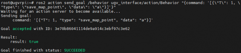
You can use Nav2 Goal in the RViz navigation interface to move the robot to the next target position and save it as the next navigation point.
After saving the navigation point, send a control command to let the robot move to the corresponding navigation point, and the data is the name of the previously saved navigation point:
ros2 action send_goal /behavior ugv_interface/action/Behavior "{command: '[{\"T\": 1, \"type\": \"pub_nav_point\", \"data\": \"a\"}]'}"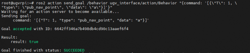
The saved navigation point information will also be stored in the map_points.txt file, which is located in the /home/ws/ugv_ws/ directory.
11. Gazebo Simulation Debugging
This chapter mainly introduces the simulation and debugging of robots. When we don’t have a physical robot at hand, we can verify robot algorithms, architecture, etc. through Gazebo, a three-dimensional robot physics simulation platform. We provide Gazebo robot models and complete function packages for simulation and debugging on virtual machines to help users conduct system verification and testing in the early stages of development.
11.1 Gazebo introduction
Gazebo is a 3D dynamic simulator that accurately and efficiently simulates groups of robot in complex indoor and outdoor environments. Although similar to game engines, Gazebo offers higher-fidelity physics simulations, supporting complex environment and sensor simulations. Users can create 3D models, set up environments, and simulate various sensors (such as lidar, cameras, etc.).
Key aspects of the Gazebo simulation platform include:
- Physics engine: Gazebo uses multiple physics engines (such as ODE, Bullet, DART, etc.) to provide accurate dynamics simulation and can handle physical phenomena such as collision, friction, and gravity.
- 3D modeling: Users can use existing model libraries or create custom 3D models through software such as Blender. These models can be robots, obstacles, or environmental elements.
- Environment settings: Gazebo allows users to design complex simulation environments, including cities, indoor scenes, etc., and can freely configure terrain and lighting.
- Sensor simulation: Gazebo supports multiple sensor types, such as lidar, camera, IMU, etc., and can provide real-time data streams to facilitate algorithm testing.
- ROS integration: The combination with ROS allows users to easily use Gazebo as a simulation environment for algorithm development and testing, and supports ROS themes and services.
- User interface: Gazebo provides an intuitive graphical user interface. Users can monitor the simulation process and adjust parameters in real time through visual tools.
11.2 Load virtual machine image
We provide Ubuntu images configured with Gazebo simulation, robot models and complete feature packages for users to use directly. This tutorial is suitable for using a virtual machine on a Windows computer to load the Ubuntu image for Gazebo simulation debugging.
11.2.1 Download Ubuntu image with software configured
Use the Ubuntu image of the configured software, there is no need to install and configure the Gazebo simulation environment by yourself, and conduct the simulation test of the product according to the subsequent tutorials.
- Download link:
Download and decompress the image, all files are image files. The disk file system of some virtual machines does not support separate files above 4G, so the configured Ubuntu image is divided into multiple files.
11.2.2 Install Oracle VM VirtualBox virtual machine
Download and install Oracle VM VirtualBox, which is a free virtual machine software that allows you to run a virtual operating system on your own computer. We run the virtual machine on a Windows system computer to install the Ubuntu operating system, and then install and configure ROS2 on the Ubuntu operating system to control the robotic arm.
It should be noted that although ROS2 has a Windows version, there is not much information about the Windows version of ROS2, so we provide a virtual machine solution by default to run ROS2.
Click Oracle VM VirtualBox official download link, the installation process is very simple, just keep clicking Next. If it is already installed, skip this step.
11.3 Load image into virtual machine software
- On the left toolbar, click New.

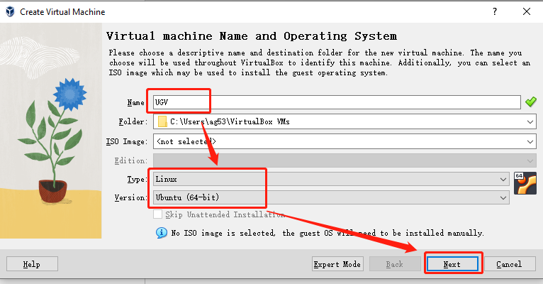
- Set the name, set the type to Linux, and set the version to Ubuntu (64-bit), click Next.
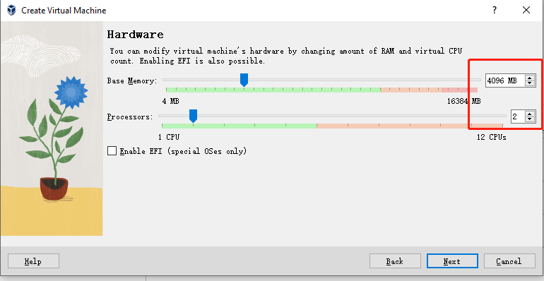
- Set the memory size to 4096MB and the processor to 2, then click Next.
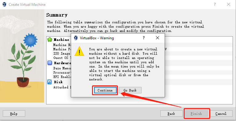
- Select Do not add a virtual hard disk, click Next to display the configuration of the new virtual computer, click Finish and a warning will pop up, then click Continue.

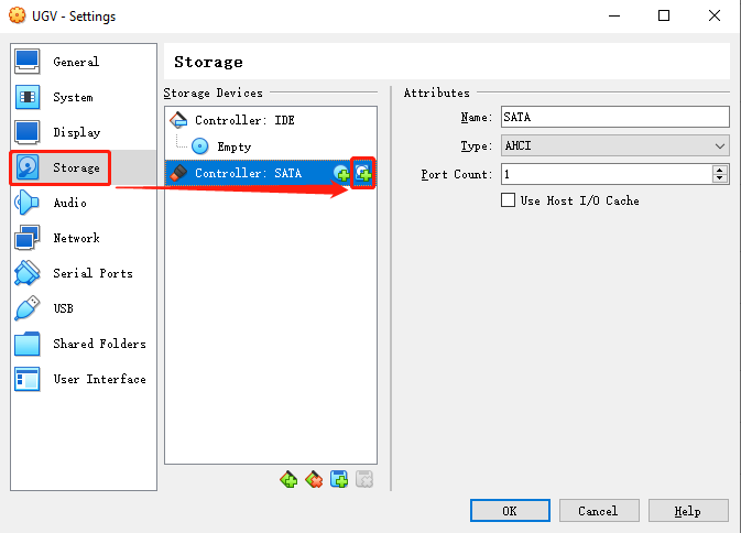
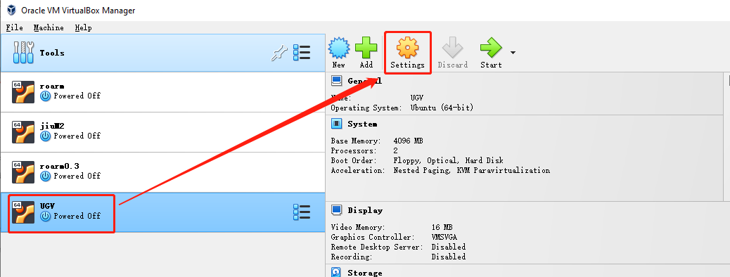
- Select the virtual machine you just created and select Settings.
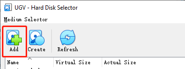
- Select Storage and click the + sign on the far right of the controller to add a virtual hard disk.
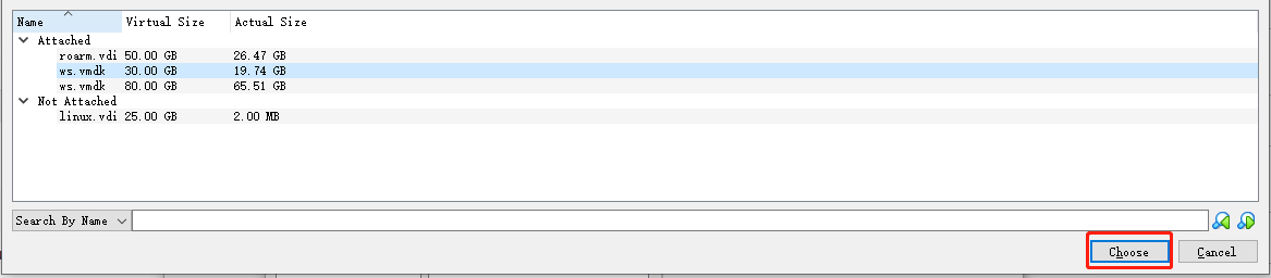
- Select Register, add the ws.vmdk image file decompressed earlier and click Select in the lower right corner, and confirm to save.
- Then select Display, check Enable 3D Acceleration and click OK, double-click the virtual computer you just created on the left to run it.

After successfully running the virtual machine computer, you can learn how to use Gazebo simulation to control the robot according to the following content.
11.4 Enter Docker container
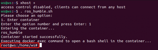
In the host terminal, first allow unauthorized users to access the graphical interface and enter the command:
xhost +
Note: After each virtual machine rerun, you need to open the visualization in the Docker container, and this step must be performed.
Then execute the script that enters the Docker container:
. ros_humble.sh
Enter 1 to enter the Docker container, and the username will change to root, as shown in the following figure.
11.5 Load Gazebo robot model
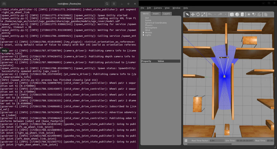
The image model defaults to a 4WD and 6 wheels UGV Rover, so we can directly load the Gazebo simulation environment and the robot model of the UGV Rover, and start the corresponding ROS 2 node:
ros2 launch ugv_gazebo bringup.launch.py
The startup needs to wait for a short period of time. As shown below, the startup is successful. This command needs to keep running in subsequent steps.
11.6 Use Joystick or Keyboard Control
11.6.1 Joystick control
Plug the joystick receiver into your computer, click on Devices above Oracle VM VirtualBox → USB → the name of the device with the word XBox, and the device name is preceded by a √ to indicate that the controller is connected to the virtual machine.
Press Ctrl+Alt+T to open a new terminal window, execute the script that goes into the Docker container, and enter 1 to enter the Docker container:
. ros_humble.sh
Run the joystick control node in the container:
ros2 launch ugv_tools teleop_twist_joy.launch.py
Then turn on the switch on the back of the joystick, and you can control the movement of the robot model when you see the red light on the joystick. Note: There are three function keys on the joystick: the key below R is used to lock or unlock, the left joystick -- forward or backward, the right joystick -- turn left or right.
You can close the joystick control node by pressing Ctrl+C.
11.6.2 Keyboard control
Close the joystick control node, and then run the joystick control node in the container terminal window to run keyboard control node:
ros2 run ugv_tools keyboard_ctrl
Keep this window active (that is, make sure you are in the terminal window interface when operating the keys), and control the movement of the robot model through the following keys:
| keyboard key | Operation desc | keyboard key | Operation desc | keyboard key | Operation desc |
| Letter U | Left forward | Letter I | Straight ahead | Letter O | Right forward |
|---|---|---|---|---|---|
| Letter J | Turn left | Letter K | Stop | Letter L | Turn right |
| Letter M | Left backward | Symbol , | Straight backward | Symbol . | Right backward |
You can close the keyboard control node by pressing Ctrl+C.
11.7 Map
11.7.1 2D Mapping
1. 2D Mapping based on Gmapping
Keep loading the Gazebo robot model running, press Ctrl+Alt+T to open a new terminal window, execute the script that goes into the Docker container, and enter 1 to enter the Docker container:
. ros_humble.sh
Run to launch the mapping node in the container:
ros2 launch ugv_gazebo gmapping.launch.py
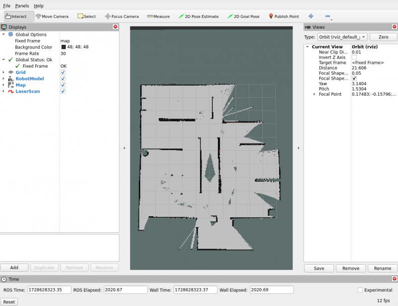
At this time, the map displayed on the RViz interface will only show the area scanned by the lidar in the Gazebo simulation map. If there are still unscanned areas that need to be mapped, you can use the joystick or keyboard to control the movement of the robot to scan and map.
In a new terminal window, execute the script that goes into the Docker container, enter 1 to enter the Docker container, and run either the joystick control or keyboard control node:
#Joystick control (make sure the joystick receiver is plugged into a virtual machine)
ros2 launch ugv_tools teleop_twist_joy.launch.py
#Keyboard control (keep the running keyboard control node active)
ros2 run ugv_tools keyboard_ctrl
In this way, you can control the movement of the chassis to realize the mapping of the surrounding environment.
After the mapping is completed, keep the mapping node running. In a new terminal window, execute the script that enters the Docker container, enter 1 to enter the Docker container, and add executable permissions to the map saving script:
cd ugv_ws/
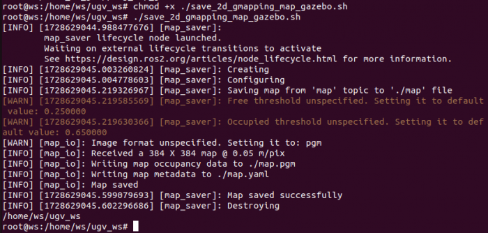
chmod +x ./save_2d_gmapping_map_gazebo.shThen run the map saving script, as shown below, the map is saved successfully:
./save_2d_gmapping_map_gazebo.sh
The details in this script are as follows:
cd /home/ws/ugv_ws/src/ugv_main/ugv_gazebo/maps
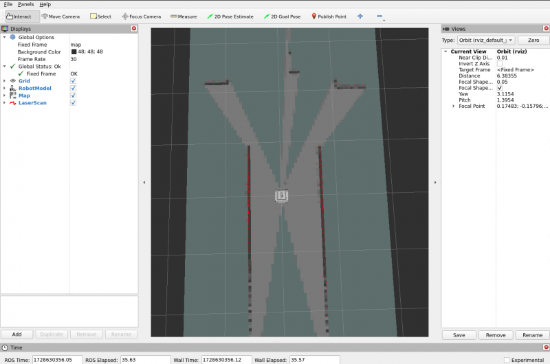
ros2 run nav2_map_server map_saver_cli -f ./mapAfter executing the above script file, a 2D raster map named map will be saved. The map is saved in the /home/ws/ugv_ws/src/ugv_main/ugv_gazebo/maps directory. You can see that two files are generated in the above directory, one is map.pgm and the other is map.yaml.
- map.pgm: This is a raster image of the map (usually a grayscale image file);
- map.yaml: This is the configuration file of the map.
Then the Gmapping mapping node can be closed via Ctrl+C.
2. 2D Mapping based on Cartographer
Keep loading the Gazebo robot model running, press Ctrl+Alt+T to open a new terminal window, execute the script that goes into the Docker container, and enter 1 to enter the Docker container:
. ros_humble.sh
Run to launch the mapping node in the container:
ros2 launch ugv_gazebo cartographer.launch.py
At this time, the map displayed on the RViz interface will only show the area scanned by the lidar in the Gazebo simulation map. If there are still unscanned areas that need to be mapped, you can use the joystick or keyboard to control the movement of the robot to scan and map.
In a new terminal window, execute the script that goes into the Docker container, enter 1 to enter the Docker container, and run either the joystick control or keyboard control node:
#Joystick control (make sure the joystick receiver is plugged into a virtual machine)
ros2 launch ugv_tools teleop_twist_joy.launch.py
#Keyboard control (keep the running keyboard control node active)
ros2 run ugv_tools keyboard_ctrl
In this way, you can control the movement of the chassis to realize the mapping of the surrounding environment.
After the mapping is completed, keep the mapping node running. In a new terminal window, execute the script that enters the Docker container, enter 1 to enter the Docker container, and add executable permissions to the map saving script:
cd ugv_ws/
chmod +x ./save_2d_cartographer_map_gazebo.sh
Then run the map saving script, as shown below, the map is saved successfully:
./save_2d_cartographer_map_gazebo.sh
The details in this script are as follows:
cd /home/ws/ugv_ws/src/ugv_main/ugv_gazebo/maps
ros2 run nav2_map_server map_saver_cli -f ./map && ros2 service call /write_state cartographer_ros_msgs/srv/WriteState "{filename: '/home/ws/ugv_ws/src/ugv_main/ugv_gazebo/maps/map.pbstream'}"
After executing the above script file, a 2D raster map named map will be saved. The map is saved in the /home/ws/ugv_ws/src/ugv_main/ugv_gazebo/maps directory. You can see that three files are generated in the directory,which are map.pgm, map.yaml and map.pbstram.
Then the Cartographer mapping node can be closed via Ctrl+C.
11.7.2 3D Mapping
1. Visualizing in RTAB-Map
RTAB-Map (Real-Time Appearance-Based Mapping) is an open source algorithm for Simultaneous Localization and Mapping (SLAM), which is widely used in robot navigation, autonomous vehicles, drones and other fields. It uses data from visual and lidar sensors to build an environment map and perform positioning. It is a SLAM method based on loop closure detection.
Keep the loaded Gazebo robot model running and start the visualization node of RTAB-Map in the container:
ros2 launch ugv_gazebo rtabmap_rgbd.launch.py
In a new Docker container terminal, run either the joystick control or keyboard control node:
#Joystick control (make sure the joystick receiver is plugged into a virtual machine)
ros2 launch ugv_tools teleop_twist_joy.launch.py
#Keyboard control (keep the running keyboard control node active)
ros2 run ugv_tools keyboard_ctrl
In this way, you can control the movement of the chassis to realize the mapping of the surrounding environment. After the mapping is completed, press Ctrl+C to exit the mapping node, and the system will automatically save the map. The default saving path of the map is ~/.ros/rtabmap.db.
2. Visualizing in RViz
Keep the loaded Gazebo robot model running and start the visualization node of RTAB-Map in the container:
ros2 launch ugv_gazebo rtabmap_rgbd.launch.py use_rviz:=trueIn a new Docker container terminal, run either the joystick control or keyboard control node:
#Joystick control (make sure the joystick receiver is plugged into a virtual machine)
ros2 launch ugv_tools teleop_twist_joy.launch.py
#Keyboard control (keep the running keyboard control node active)
ros2 run ugv_tools keyboard_ctrl
In this way, you can control the movement of the chassis to realize the mapping of the surrounding environment. After the mapping is completed, press Ctrl+C to exit the mapping node, and the system will automatically save the map. The default saving path of the map is ~/.ros/rtabmap.db.
Before you start navigating, make sure you have built a map of the environment called map, and if you haven't followed the previous tutorial, you need to build a map according to the previous tutorial.
After the mapping is completed, then start the navigation, we provide a variety of autonomous navigation modes, you can choose one of the following autonomous navigation modes for robot navigation.
- AMCL algorithm
Adaptive Monte Carlo Localization (AMCL) is a particle filter-based positioning algorithm in ROS 2 that uses 2D lidar to estimate the position and direction (i.e. posture) of the robot in a given known map. AMCL is mainly used for mobile robot navigation. It matches existing maps with laser sensors (such as lidar) to calculate the robot's position and direction in the map. The core idea is to represent the possible position of the robot through a large number of particles, and gradually update these particles to reduce the uncertainty of the robot's pose.
Advantages of AMCL:
- Adaptive particle number: AMCL will dynamically adjust the number of particles based on the uncertainty of the robot's position.
- Suitable for dynamic environments: While AMCL assumes a static environment, it can handle a small number of dynamic obstacles, such as pedestrians and other moving objects, to a certain extent, which makes it more flexible in practical applications.
- Reliable positioning capability: AMCL's positioning effect in known maps is very reliable. Even if the robot's pose is initially uncertain, it can gradually converge to the correct pose.
AMCL assumes that the map is known and you cannot create the map yourself. It also relies on high-quality static maps that are matched to sensor data. If there is a big difference between the map and the real environment, the positioning effect will be affected. AMCL is often used for autonomous navigation of mobile robots. During the navigation process, the robot can determine its own pose through AMCL and rely on known maps for path planning and obstacle avoidance.
In the container, start navigation based on the AMCL algorithm. After successful startup, you can see the RViz screen of the previously built map:
ros2 launch ugv_gazebo nav.launch.py use_localization:=amcl
Then, you can determine the initial position of the robot according to the subsequent tutorials.
- EMCL algorithm
EMCL is an alternative Monte Carlo localization (MCL) package to AMCL. Unlike AMCL, KLD sampling and adaptive MCL are not implemented. Instead, extended resets and other features are implemented. EMCL does not rely entirely on adaptive particle filtering, but introduces methods such as extended reset to improve positioning performance. EMCL implements the extended reset strategy, a technique for improving the quality of particle sets to better handle uncertainty and drift in positioning.
Start the navigation based on the EMCL algorithm. After successful startup, you can see the RViz screen of the previously built map:
ros2 launch ugv_gazebo nav.launch.py use_localization:=emcl
Then, you can determine the initial position of the robot according to the subsequent tutorials.
- Pure positioning based on Cartographer
Cartographer is an open-source Google system that provides real-time simultaneous localization and mapping (SLAM) in 2D and 3D across multiple platforms and sensor configurations.
Cartographer system architecture overview: You can see that the optional inputs on the left include depth information, odometer information, IMU data, and fixed Frame attitude.
For more tutorials, please refer to Cartographer official document and project address.
Start pure positioning based on Cartographer. After successful startup, you can see the RViz screen of the previously built map:
Note: The navigation mode based on Cartographer's pure positioning can only be used after using Cartographer to build the map.
ros2 launch ugv_gazebo nav.launch.py use_localization:=cartographer
Then, you can determine the initial position of the robot according to the subsequent tutorials.
- DWA algorithm
Dynamic Window Approaches (DWA) is a suboptimal method based on predictive control theory, because it can safely and effectively avoid obstacles in an unknown environment, and has the characteristics of small computational effort, rapid response and strong operability. The DWA algorithm is a local path planning algorithm.
The core idea of this algorithm is to determine a sampling speed space that satisfies the mobile robot's hardware constraints in the speed space (v, ω) based on the current position and speed status of the mobile robot, and then calculate the trajectories of the mobile robot within a certain period of time under these speed conditions. trajectory, and evaluate the trajectories through the evaluation function, and finally select the speed corresponding to the trajectory with the best evaluation as the movement speed of the mobile robot. This cycle continues until the mobile robot reaches the target point.
Start the navigation based on the DWA algorithm. After successful startup, you can see the RViz screen of the previously built map:
ros2 launch ugv_gazebo nav.launch.py use_localplan:=dwa
Then, you can determine the initial position of the robot according to the subsequent tutorials.
- TEB algorithm
TEB stands for Time Elastic Band Local Planner. This method performs subsequent corrections on the initial global trajectory generated by the global path planner to optimize the robot's motion trajectory and belongs to local path planning. During the trajectory optimization process, the algorithm has a variety of optimization objectives, including but not limited to: overall path length, trajectory running time, distance from obstacles, passing intermediate way points, and compliance with robot dynamics, kinematics, and geometric constraints.
Start the navigation based on the TEB algorithm. After successful startup, you can see the RViz screen of the previously built map:
ros2 launch ugv_gazebo nav.launch.py use_localplan:=teb
Then, you can determine the initial position of the robot according to the subsequent tutorials.
The map navigation mode introduced above is based on the 2D construction of LiDAR. For the 3D map built according to previous tutorial, please refer to the navigation startup method in this subsection.
Enable nav positioning:
ros2 launch ugv_gazebo rtabmap_localization_launch.py
You need to wait for the 3D data to be loaded, wait for a period of time, and then you can start navigation as shown in the figure below.
In a new terminal, turn on navigation and choose one of the two navigation modes:
- DWA algorithm
ros2 launch ugv_gazebo nav_rtabmap.launch.py use_localplan:=dwa
- TEB algorithm
ros2 launch ugv_ngazebo nav_rtabmap.launch.py use_localplan:=teb
Choose a navigation mode based on the map created above to start the navigation, then proceed with the following content.
11.8.2 Initialize the robot's position
By default, when navigation is started, the robot initially has no idea where it is and the map waits for you to provide it with an approximate starting location.
First, find the robot's location on the map and check the actual location of your robot. Manually set the robot's initial pose in RViz. Click the 2D Pose Estimate button and indicate the robot's location on the map. The direction of the green arrow is the direction the robot pan-tilt is facing forward.
Keep the operation of the navigation terminal, set the approximate initial pose of the robot, and ensure that the navigation ensures that the actual position of the robot is roughly corresponding to the ground. You can also control the robot through the keyboard on a new terminal to simply move and rotate it to assist in initial positioning.
ros2 run ugv_tools keyboard_ctrl
11.8.3 Send target pose
Select a target location for the robot on the map. You can use the Nav2 Goal tool to send the target location and direction to the robot. Indicate the location (target point) that the robot wants to navigate to automatically on the RViz map. The direction of the green arrow is the direction the robot pan-tilt is facing forward.
Once the target pose is set, the navigation will find the global path and begin navigating to move the robot to the target pose on the map. Now you can see the robot moving towards the actual target location.
In the lower left corner of the RViz interface, there is a Nav2 RViz2 plug-in [Waypoint/Nav Through Poses Mode], which can switch the navigation mode. Click the [Waypoint/Nav Through Poses Mode] button to switch to the multi-point navigation mode.
Then use Nav2 Goal in the RViz2 toolbar to give multiple target points to move. After setting, click [Start Waypoint Following] in the lower left corner to start path planning navigation. The robot will move according to the order of the selected target points. After reaching the first target point, it will automatically go to the next target point without any further operation. The robot will stop if it reaches the last target point.
[Tutorial Navigation]
- 1. Preparation
- 1.1 End the main program
- 1.2 Disable the main program from running automatically
- 1.3 Start Docker remote service
- 1.4 Remote login to Docker container
- 2. Rviz View product model
- 3. Use Joystick or Keyboard Control
- 4. Mapping Based on LiDAR
- 5. 3D Mapping Based on Depth Camera
- 6. Automatic Navigation
- 6.1 Start navigation
- 6.1.1 2D map navigation
- 6.1.1.1 Navigation based on AMCL and EMCL
- 6.1.1.2 Pure positioning based on Cartographer
- 6.1.1.3 Based on DWA and TEB algorithms
- 6.1.2 3D map navigation
- 6.2 Initialize the robot's position
- 6.3 Send target pose
- 6.4 Change map name
- 7. Navigation and SLAM mapping
- 8. Web Natural Language Interaction
- 8.1 Ollama introduction
- 8.2 Install and configure Ollama
- 8.3 Download large model to local
- 8.4 Change IP address
- 8.5 Chassis drive
- 8.6 Launch Web AI application
- 9. Web Control Tool
- 10. Command interaction
- 10.1 Basic control
- 10.2 Get current point location
- 10.3 Save as navigation point
- 10.4 Move to navigation point
- 11. Gazebo Simulation Debugging
- 11.1 Gazebo introduction
- 11.2 Load virtual machine image
- 11.2.1 Download Ubuntu image with software configured
- 11.2.2 Install Oracle VM VirtualBox virtual machine
- 11.3 Load image into virtual machine software
- 11.4 Enter Docker container
- 11.5 Load Gazebo robot model
- 11.6 Use Joystick or Keyboard Control
- 11.7 Map
- 11.8 Navigate