


- sales/support
Google Chat:---
- sales
+86-0755-88291180
- sales01
sales@spotpear.com
- sales02
dragon_manager@163.com
- support
tech-support@spotpear.com
- CEO-Complaints
zhoujie@spotpear.com
- Only Tech-Support
WhatsApp:13246739196
- Purchase/Shipping/Refund
WhatsApp:13424403025
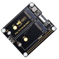
PCIe TO 2-CH M.2 HAT+ (B) User Guide
Features
- Support NVMe protocol and M.2 solid state drive protocol, high-speed read/write, with high work efficiency.
- PCI-E×1 only supports Gen2 modes.
- Only supports PI5B.
- Onboard working indicator lights, with PWR on continuously when powered, and ACT blinking during read/write.
- HAT+ design with onboard EEPROM chip.
- Onboard power monitoring chip for real-time monitoring the operation status of the solid state drive.
- Support NVME SSD booting.
Note
- As the Raspberry Pi does not support NVME booting, the config text should be modified.
Load
1: Enable PCIe Interface:
PCIE interface is enabled on the PI5B by default.
If the PCIE interface is not enabled, you add the following content in "/boot/firmware/config.txt":
dtparam=pciex1
2: The module only supports PCIE gen2 x1.
3: After modifying it and restarting PI5, you can recognize the device.
As shown below, the identified SM2263 is my SSD, and the other PI5 is the RPI chip.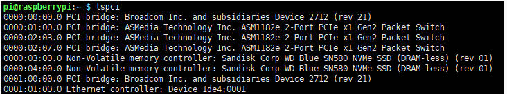
4: Note that skip this step if you have partitioned and formatted on other platforms (will delete all data from the SSD and proceed with caution).
lsblk for viewing the disk (If you want to see the details run sudo fdisk -l)Partition sudo fdisk /dev/nvme0n1 The device number is the total device number, don't add p1, that's just one partition How to use fdisk partition tool n New Partition q Exit without saving p Print partition table m Print selection menu d Delete Partition w Save to exit t Modify ID number Execute n to add the partition, at last execute w to save and exit.
5: Format:
sudo mkfs.  Then press the tab to see a variety of different suffixes, the different suffixes are the formats you need to format.

If I want to format to the ext4 file format, execute the following command:
sudo mkfs.ext4 /dev/nvme0n1p1
Wait for a few moments, when done has appeared, it means that the formatting has been carried out.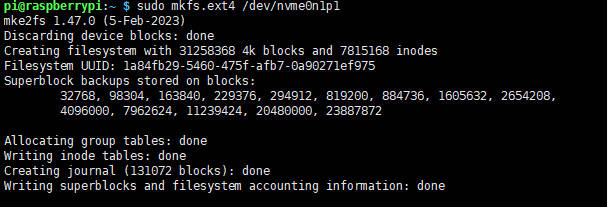
6: Mount:
Create Mount Directory
sudo mkdir toshiba
Mount the device
sudo mount /dev/nvme0n1p1 ./toshiba
Checking disk status
df -h
Read/Write Test
Enter the directory where the disk is mounted:
cd toshiba
- Release memory:
sudo sh -c "sync && echo 3 > /proc/sys/vm/drop_caches"
- Copying the contents of the Raspberry Pi's memory to the hard drive (Write):
sudo dd if=/dev/zero of=./test_write count=2000 bs=1024k

- Copying the contents of the hard drive to the Raspberry Pi's memory ("/etc/fstab" for reading):
sudo dd if=./test_write of=/dev/null count=2000 bs=1024k

- Note: Different cards and environments make different test results. As the Raspberry Pi is more vulnerable to being affected, if you want to test the exact performance, you can use a PC to test.
Auto-mounting
If the testing is sound and you don't need it as a system disk and only use an extended disk, you can set up an automatic mounting.
sudo nano /etc/fstab

#Add the following content at the end:
/dev/nvme0n1p1  /home/pi/toshiba  ext4  defaults  0  0
#/dev/nvme0n1p1 is the device name, /home/pi/toshiba is the directory to be mounted, ext4 is the file system type, defaults are using the default mounting setting
#Make the changes take effect (make sure test without problems before rebooting, otherwise it will lead to failure to mount or boot)
sudo mount -a

#And then reboot
Check the device through "lsblk"
Booting from NVMe SSD
1: First, you can use an SD card to boot the Raspberry Pi, just test it to make sure the hardware can work properly.
2: Use the SD card to boot the Raspberry Pi and modify the config file, modify BOOT_ORDER:
sudo rpi-eeprom-config --edit
Add:
NVME_CONTROLLER=1
Modify BOOT_ORDER=0xf41 as BOOT_ORDER=0xf416For more details, you can refer to BOOT_ORDER If you want to realize SD card boot priority, change to BOOT_ORDER=0xf461 Note: The board has onboard two or more M.2 ports, one of them is used as boot, it is recommended to connect the SSD used as boot to NVME1, the priority is NVME1 first.
3: Reboot the Raspberry Pi:
If you fail after trying several times, you can connect it to the network before modify again (wait for network time synchronization), or set the correct time before modifying the file.
4: Flash the system to NVME, and then connect to the board, remove the SD card, and power it on again.
NVME Power Monitoring
Note:【MPS2280D】& 【X1004】 do not have this function
The onboard INA219 chip can detect the voltage and current, easy to monitor the device status and monitor the input 5V voltage status (not 3.3V).
The default I2C address is 0x40, addresses can be modified via back resistors to support stacking of different expansion boards.
Demo:
wget https://files.waveshare.com/upload/0/06/PCIE_HAT_INA219.zip
unzip -o PCIE_HAT_INA219.zip -d ./PCIE_HAT_INA219
cd PCIE_HAT_INA219
sudo python INA219.py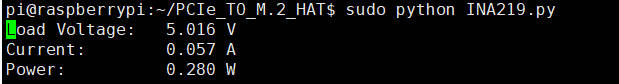
Resource
Datasheet
Note:【MPS2280D】& 【X1004】 do not have this function
FAQ
Question:Does it support Hailo-8?
Yes, but the rate only supports GEN2 mode, and the other one has to take up the rate, so the performance may not be at best.
Support
Monday-Friday (9:30-6:30) Saturday (9:30-5:30) -China time
Email: services01@spotpear.com