




- sales/support
Google Chat:---
- sales
+86-0755-88291180
- sales01
sales@spotpear.com
- sales02
dragon_manager@163.com
- support
tech-support@spotpear.com
- CEO-Complaints
zhoujie@spotpear.com
- Only Tech-Support
WhatsApp:13246739196
- Purchase/Shipping/Refund
WhatsApp:13424403025
- HOME
- >
- ARTICLES
- >
- Common Moudle
- >
- Power
ESP32-S3-CAN-2CH User Guide
Product Overview
The ESP32-S3-CAN-2CH is an industrial-grade Wi-Fi wireless communicator based on the ESP32-S3 main controller, supporting peripheral interfaces such as Wi-Fi, Bluetooth, and CAN. It features built-in power isolation, optocoupler isolation, and other protection circuits, making it safe, stable, and reliable for AIoT applications.
Features
- Based on ESP32-S3 microcontroller with Xtensa 32-bit LX7 dual-core processor with frequency up to 240MHz
- Integrated 2.4 GHz Wi-Fi and Bluetooth 5 (LE) dual-mode wireless communication with excellent RF performance
- Two onboard isolated CAN interfaces for easy expansion and connection to various CAN devices
- Onboard pin header, allowing access to other devices
- Onboard USB Type-C port for power supply, firmware downloading and debugging, making development more convenient
- Onboard power supply screw terminal, supports 7-36V wide voltage input, suitable for industrial applications
- Onboard RTC clock chip, supports timing tasks
- Onboard digital isolation to avoid external signal interference with the control chip
- Onboard integrated power isolation, providing stable isolation voltage, no extra power supply required for the isolated terminal
- Onboard CAN working indicator lights for easily monitoring the device's operating status
- Rail-mounted protective enclosure, easy to install, safe to use
Specifications
| Model | ESP32-S3-CAN-2CH | ESP32-S3-CAN-2CH-U | |
|---|---|---|---|
| Antenna Interface | Onboard SMD ceramic antenna | External antenna | |
| Microcontroller | ESP32-S3 (ESP32-S3R8 chip by default, customizable) | ||
| Wireless Communication | 2.4 GHz Wi-Fi (802.11 b/g/n), Bluetooth 5 (LE) | ||
USB | Interface Type | USB Type-C | |
| Supply Voltage | 5V | ||
| Function | Power supply, USB communication, firmware downloading, etc. | ||
Isolated | Interface Type | Screw terminal | |
| Communication Protocol | Supports CAN 2.0A / CAN 2.0B, | ||
| Interface Protection | Provides TVS diode protection, surge protection, and ESD protection | ||
| Matching Resistor | NC by default, with a reserved 120R matching resistor that can be enabled via jumper cap | ||
| Indicator | PWR | Power indicator, steady red when powered by USB or external power | |
| CAN_1 | CAN indicator, blinks when there is data communication on the CAN interface | ||
| CAN_2 | |||
| Power Supply Screw Terminal | Power Supply Range | 7V - 36V | |
| Appearance | Case | DIN-rail protective case | |
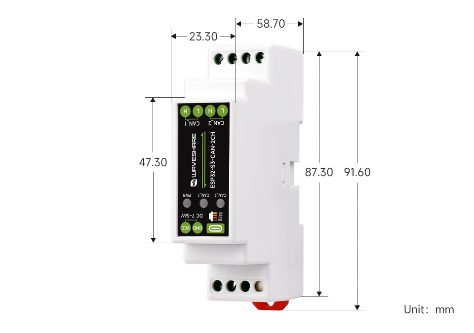
| Dimensions | 91.6 × 23.3 × 58.7 (mm) | ||
Onboard Resources
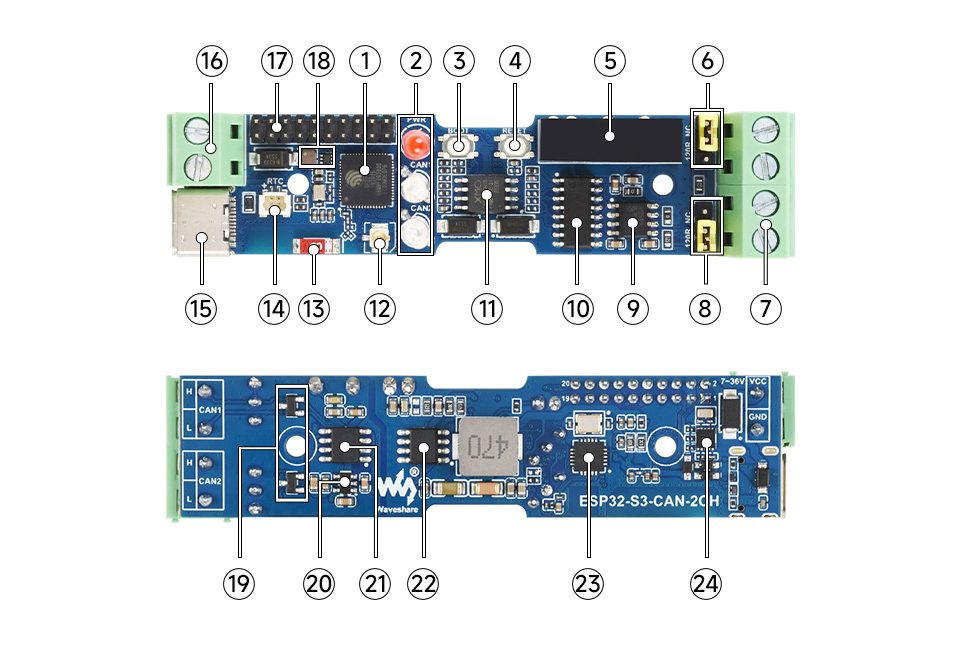
- ESP32-S3 Up to 240 MHz, equipped with 2.4 GHz Wi-Fi and Bluetooth LE
- LED indicators
- PWR: Power indicator
- CAN_1: Lights green when data is sent from the CAN_1 interface, lights blue when data is received from the CAN_1 interface
- CAN_2: Lights green when data is sent from the CAN_2 interface, lights blue when data is received from the CAN_2 interface
- ESP32 BOOT button
- ESP32 RESET button
- Power isolation Provides stable isolation voltage, no additional power supply required on the isolated side
- CAN_1 matching resistor Reserved 120R matching resistor, can be enabled with jumper cap
- CAN communication interface Used to connect external CAN devices
- CAN_2 matching resistor Reserved 120R matching resistor, can be enabled with jumper cap
- CAN transceiver chip
- Digital isolation Prevents external signals from interfering with the control chip
- 16MB Flash
- IPEX 1 connector The external antenna version connects an external antenna through this connector (routed out via the SMA connector on the enclosure)
- Onboard ceramic antenna The onboard antenna version uses this onboard antenna
- RTC battery header For connecting a rechargeable RTC battery (SH1.0)
- USB Type-C port Can be used for device power supply, firmware download, and USB communication
- Power supply screw terminal Supports DC 7-36V wide voltage input
- Pin header (2.0mm pitch) Can connect other functional modules via the pin header
- DC-DC power module Power module, supports up to 3.3 V 2 A output
- TVS diode (Transient Voltage Suppressor) Effectively suppresses surge voltage and transient spike voltage in the circuit
- ME6217C33M5G Low dropout LDO, current (Max) 800 mA
- CAN transceiver chip
- DC-DC power chip
- XL2515QF20 CAN controller
- RTC chip PCF85063 RTC clock
Interface Introduction
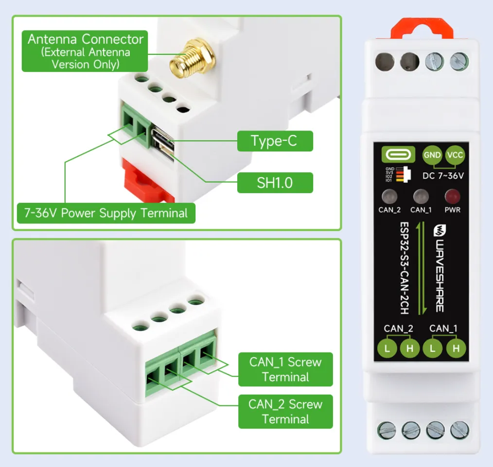
| Upper Terminal Description | Lower Terminal Description | |||
|---|---|---|---|---|
| Power Terminal | Power positive: DC 7V - 36V | CAN_1 Terminal | H signal pin | |
| Power negative | ||||
| Type-C | Can be used for device power supply, | L signal pin | ||
| SH1.0 | GND | Ground | CAN_2 Terminal | H signal pin |
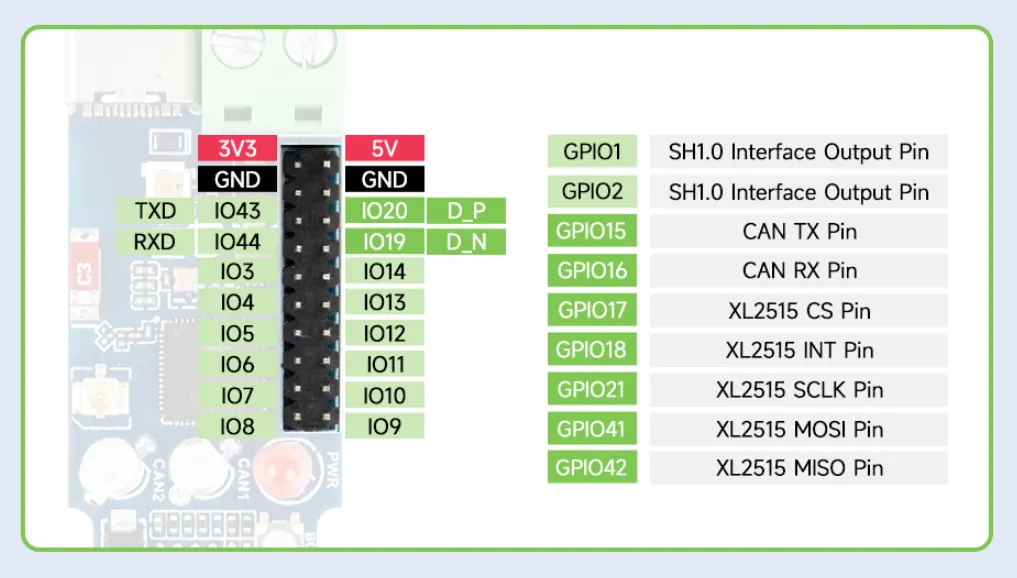
| 3V3 | 3.3V power output | |||
| GPIO2 | Exposed I/O | L signal pin | ||
| GPIO1 | Exposed I/O | |||
Dimensions
Working with Arduino
This chapter includes the following sections. Please read as needed:
Arduino Getting Started
New to Arduino ESP32 development and looking for a quick start? We have prepared a comprehensive Getting Started Tutorial for you.
- Section 0: Getting to Know ESP32
- Section 1: Installing and Configuring Arduino IDE
- Section 2: Arduino Basics
- Section 3: Digital Output/Input
- Section 4: Analog Input
- Section 5: Pulse Width Modulation (PWM)
- Section 6: Serial Communication (UART)
- Section 7: I2C Communication
- Section 8: SPI Communication
- Section 9: Wi-Fi Basics
- Section 10: Web Server
- Section 11: Bluetooth
- Section 12: LVGL GUI Development
- Section 13: Comprehensive Project
Note: This tutorial uses the ESP32-S3-Zero as a reference example, and all hardware code is based on its pinout. Before you start, we recommend checking the pinout of your development board to ensure the pin configuration is correct.
Setting Up the Development Environment
1. Install and Configure Arduino IDE
Install the ESP32 Board
- To use ESP32-related boards in Arduino IDE, you must first install the "esp32 by Espressif Systems" board package.
- Follow the board installation requirements for installation. "Online installation" is generally recommended. If online installation fails, use "offline installation".
- For a detailed installation tutorial, see: Arduino Board Management Tutorial
ESP32-S3-CAN-2CH required development board installation description
| Board Name | Board Installation Requirement | Version Requirement |
|---|---|---|
| esp32 by Espressif Systems | "Offline Installation" / "Online Installation" | 3.2.1 |
2. Installing Libraries
- There are usually two ways to install Arduino libraries: online installation and offline installation. If the library installation requires offline installation, you must use the provided library files. For most libraries, you can easily search for and install them through the Arduino online Library Manager. However, some open-source or custom libraries are not synchronized to the Arduino Library Manager, so they cannot be found through online search. In this case, you can only install these libraries manually offline.
- For a detailed library installation tutorial, see: Arduino Library Manager Tutorial
- The ESP32-S3-CAN-2CH library files are stored in the example program. Click here to go to: ESP32-S3-CAN-2CH Example
Library installation instructions for ESP32-S3-CAN-2CH
| Library Name | Description | Version | Library Installation Requirement |
|---|---|---|---|
| ArduinoJson | Lightweight JSON library | v6.21.4 | Online or offline installation |
| PubSubClient | MQTT message publish/subscribe library | v2.8.0 | Online or offline installation |
| NTPClient | Network time synchronization client library | v3.2.1 | Online or offline installation |
Example

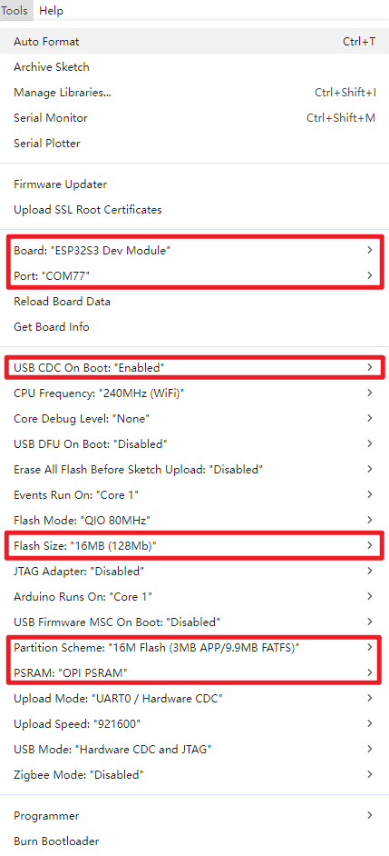
Arduino Project Settings
ESP32-S3-CAN-2CH Example
| Example | Description | Notes |
|---|---|---|
| 01_WIFI_AP | CAN interface control, Bluetooth control, Bluetooth IP transmission, Web page control (short range) | Can be flashed directly; the Web page is only available after connecting to the device's Wi-Fi |
| 02_WIFI_STA | CAN interface control, Bluetooth control, Bluetooth IP transmission, Web page control (short range) | Requires modifying the Wi-Fi to connect to; the Web page is only available on the local network |
01_WIFI_AP
Example Description
- This example implements CAN interface control over Wi-Fi. This example enables the Wi-Fi AP mode.
Notes
- Can be flashed directly
- The Web page can only be used when connected to the device's Wi-Fi
Web Page Control
Use a mobile Bluetooth debug assistant to connect to the ESP32-S3-CAN-2CH device, obtain the IP after connecting to Wi-Fi, and open the Web page via the IP.
- Connect to the Wi-Fi of the ESP32-S3-CAN-2CH device. The Wi-Fi name is ESP32-S3-CAN-2CH, and the password is waveshare.
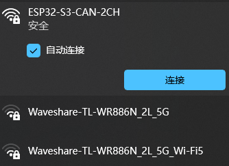
- Check the serial port or use a Bluetooth debug assistant to get the current IP
- Open the Web page to control the CAN interface (after the device is powered on, it takes a short time to configure. The first time the Web page is opened after each power-on may be slow.)
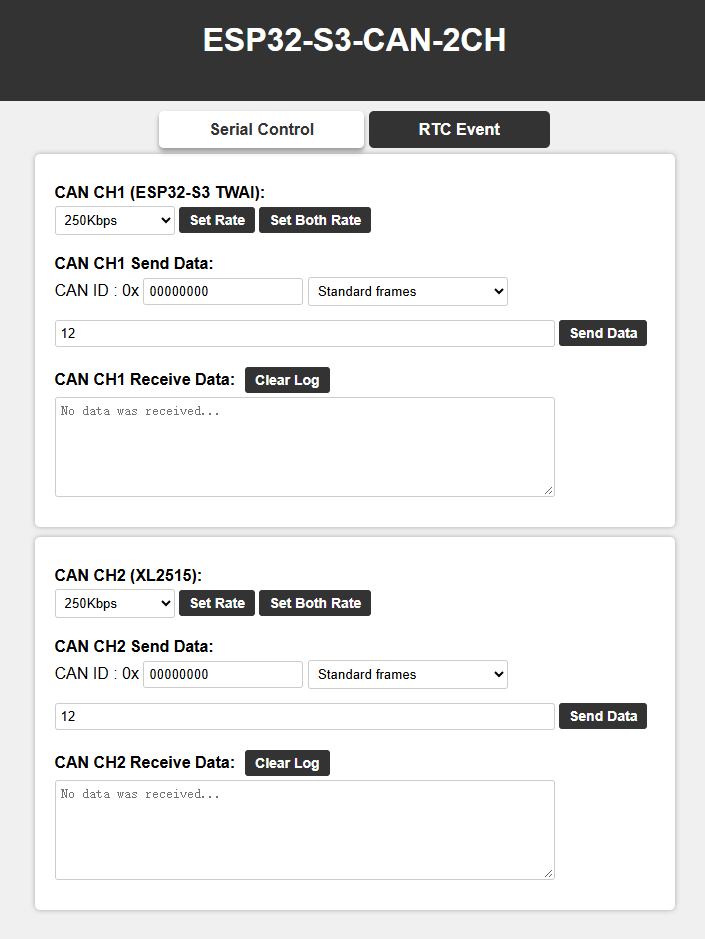
02_WIFI_STA
Example Description
- This example implements CAN interface control over Wi-Fi. This example enables the Wi-Fi STA mode.
Notes
- Requires modifying the Wi-Fi to connect to
- The Web page only supports controlling the device when it is on the same network as this product. If using a mobile phone for control, mobile data must be turned off.
Web Page Control
Use a mobile Bluetooth debug assistant to connect to the ESP32-S3-CAN-2CH device, obtain the IP after connecting to Wi-Fi, and open the Web page via the IP.
- Before flashing the program, open
MAIN_WIFI_STA/WS_Information.hand changeSTASSIDandSTAPSKto the Wi-Fi name and password you want to connect to, respectively. After the device is powered on, it will automatically connect to the configured Wi-Fi. - Check the serial port or use a Bluetooth debug assistant to get the current IP
- Open the Web page to control the CAN interface (after the device is powered on, it takes a short time to configure. The first time the Web page is opened after each power-on may be slow.)
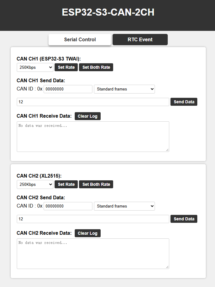
ESP-IDF
This chapter includes the following sections. Please read as needed:
ESP-IDF Getting Started
New to ESP32 ESP-IDF development and looking to get started quickly? We have prepared a general Getting Started Tutorial for you.
- Section 1: Environment Setup
- Section 2: Running Examples
- Section 3: Creating a Project
- Section 4: Using Components
- Section 5: Debugging
- Section 6: FreeRTOS
- Section 7: Peripherals
- Section 8: Wi-Fi Programming
- Section 9: BLE Programming
Please Note: This tutorial uses the ESP32-S3-Zero as a teaching example, and all hardware code is based on its pinout. Before you start, it is recommended that you check the pinout of your development board to ensure the pin configuration is correct.
Setting Up the Development Environment
For the ESP32-S3-CAN-2CH development board, ESP-IDF version V5.5.2 or above is required.
The following guide uses Windows as an example, demonstrating development using VS Code + the ESP-IDF extension. macOS and Linux users should refer to the official documentation.
The screenshots in this section use ESP-IDF V5.5.2 as an example. When installing, please select the ESP-IDF version that matches your board's example.
Install the ESP-IDF Development Environment
Download the installation manager from the ESP-IDF Installation Manager page. This is Espressif's latest cross-platform installer. The following steps demonstrate how to use its offline installation feature.
Click the Offline Installer tab on the page, then select Windows as the operating system and the ESP-IDF version you need (the version shown in the screenshot is for reference only — choose the version that fits your actual needs).
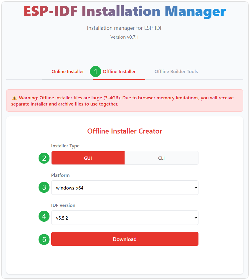
After confirming your selection, click the download button. The browser will automatically download two files: the ESP-IDF Offline Package (.zst) and the ESP-IDF Installer (.exe).
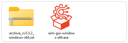
Please wait for both files to finish downloading.
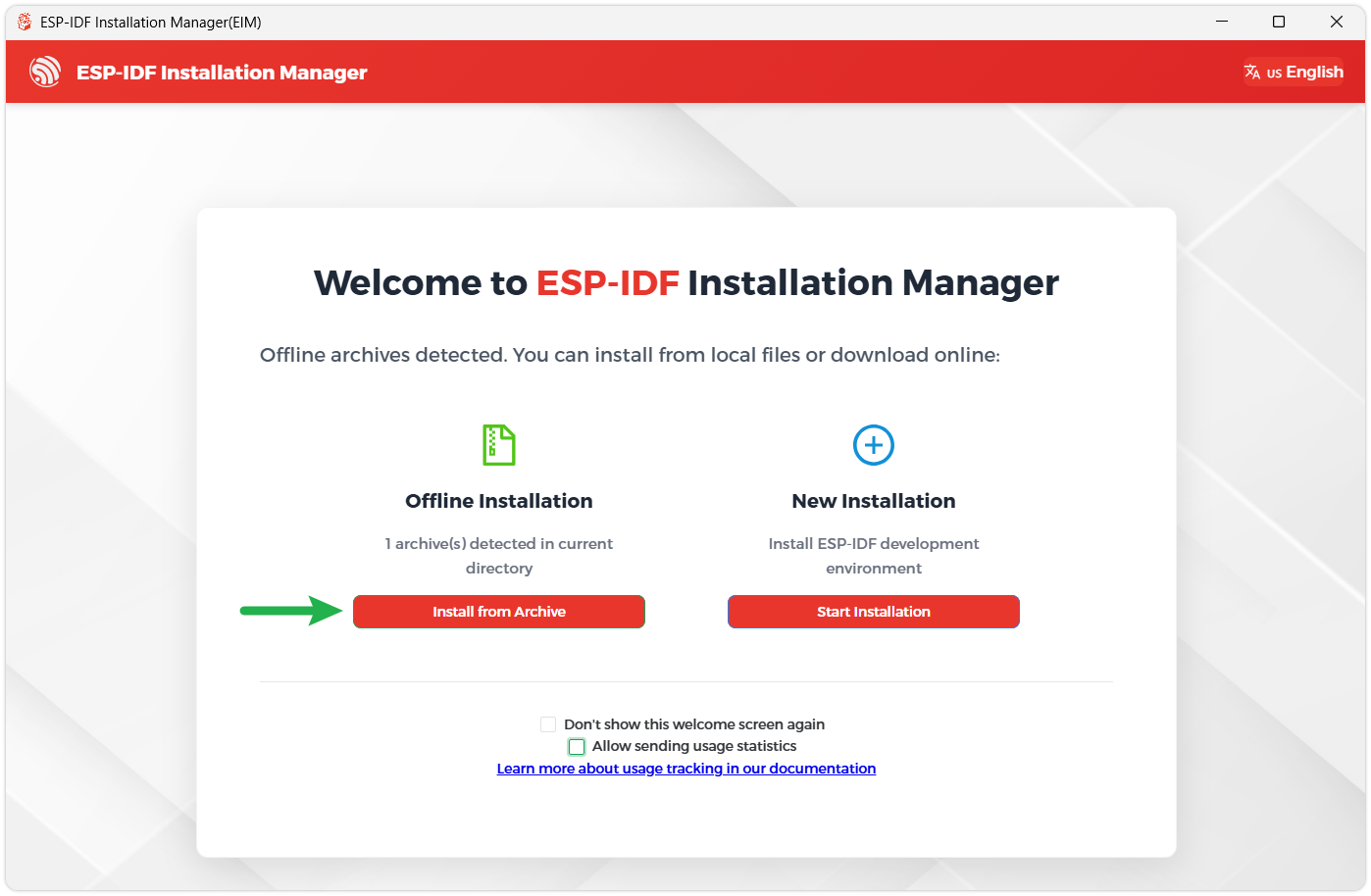
Once the download is complete, double-click to run the ESP-IDF Installer (eim-gui-windows-x64.exe).
The installer will automatically detect if the offline package exists in the same directory. Click Install from archive.
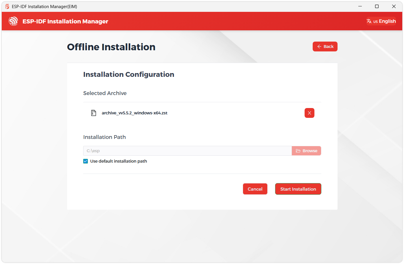
Next, select the installation path. We recommend using the default path. If you need to customize it, ensure the path does not contain Chinese characters or spaces. Click Start installation to proceed.
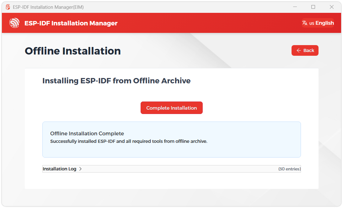
When you see the following screen, the ESP-IDF installation is successful.
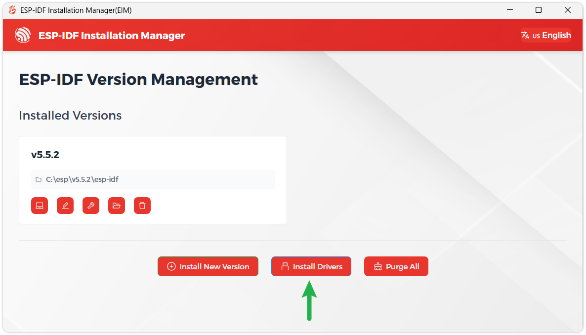
We recommend installing the drivers as well. Click Finish installation, then select Install driver.
Install Visual Studio Code and the ESP-IDF Extension
Download and install Visual Studio Code.
During installation, it is recommended to check Add "Open with Code" action to Windows Explorer file context menu to facilitate opening project folders quickly.
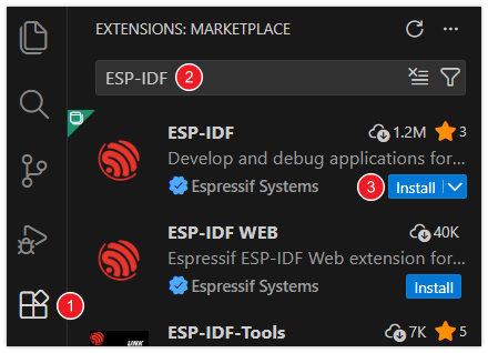
In VS Code, click the Extensions icon
 in the Activity Bar on the side (or use the shortcut Ctrl + Shift + X) to open the Extensions view.
Enter ESP-IDF in the search box, locate the ESP-IDF extension, and click Install.
For ESP-IDF extension versions ≥ 2.0, the extension will automatically detect and recognize the ESP-IDF environment installed in the previous steps, requiring no manual configuration.
Example
| Example | Description | Notes |
|---|---|---|
| 01_WIFI_AP | CAN interface control, Bluetooth control, Bluetooth IP transmission, Web page control (short range) | Can be flashed directly; the Web page is only available after connecting to the device's Wi-Fi |
| 02_WIFI_STA | CAN interface control, Bluetooth control, Bluetooth IP transmission, Web page control (short range) | Requires modifying the Wi-Fi to connect to; the Web page is only available on the local network |
01_WIFI_AP
Example Description
- This example implements CAN interface control over Wi-Fi. This example enables the Wi-Fi AP mode.
Notes
- Can be flashed directly
- The Web page can only be used when connected to the device's Wi-Fi
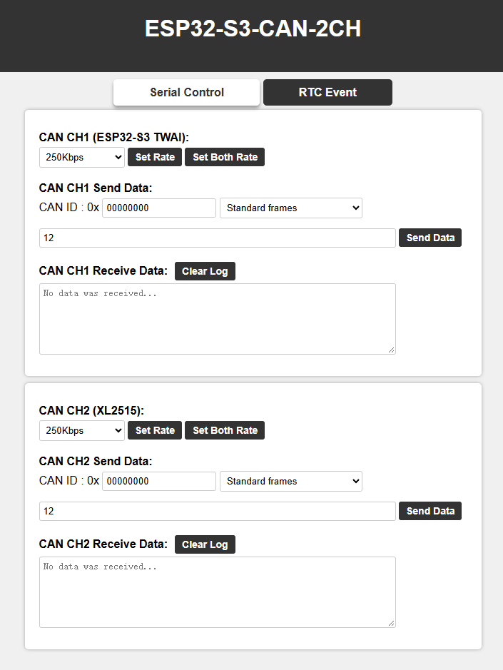
Web Page Control
Use a mobile Bluetooth debug assistant to connect to the ESP32-S3-CAN-2CH device, obtain the IP after connecting to Wi-Fi, and open the Web page via the IP.
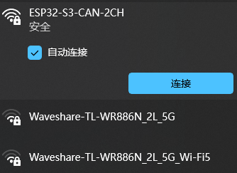
- Connect to the Wi-Fi of the ESP32-S3-CAN-2CH device. The Wi-Fi name is ESP32-S3-CAN-2CH, and the password is waveshare.
- Check the serial port or use a Bluetooth debug assistant to get the current IP
- Open the Web page to control the CAN interface (after the device is powered on, it takes a short time to configure. The first time the Web page is opened after each power-on may be slow.)
02_WIFI_STA
Example Description
- This example implements CAN interface control over Wi-Fi. This example enables the Wi-Fi STA mode.
Notes
- Requires modifying the Wi-Fi to connect to
- The Web page only supports controlling the device when it is on the same network as this product. If using a mobile phone for control, mobile data must be turned off.
Web Page Control
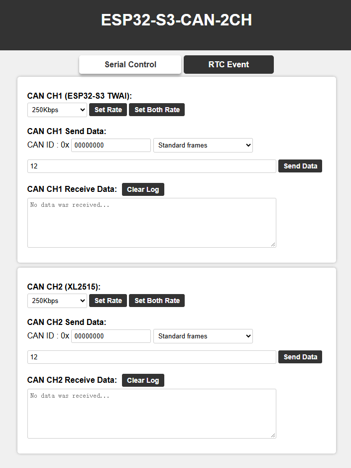
Use a mobile Bluetooth debug assistant to connect to the ESP32-S3-CAN-2CH device, obtain the IP after connecting to Wi-Fi, and open the Web page via the IP.
- Before flashing the program, open
components/esp_bsp/bsp_common.hand changeWS_STA_SSIDandWS_STA_PASSto the Wi-Fi name and password you want to connect to, respectively. The device will automatically connect to the configured Wi-Fi after power-on. - Check the serial port or use a Bluetooth debug assistant to get the current IP
- Open the Web page to control the CAN interface (after the device is powered on, it takes a short time to configure. The first time the Web page is opened after each power-on may be slow.)
Firmware Flashing and Erasing
This product provides test firmware that can be flashed directly to verify whether the onboard devices are functioning properly.
- Firmware download: ESP32-S3-CAN-2CH Example. The bin file is located in the
firmwaredirectory. - Flash address:
0x00
- Firmware Flashing
- Firmware Erasing
The following steps apply to the firmware provided on this page.
Download and extract Espressif's official Flash Download Tool (Download)
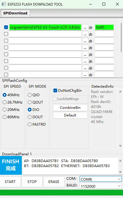
Run Flash Download Tool and select the options that match the development board's MCU and download interface. The screenshot below uses ESP32-S3 and USB as an example; use the options required by the product's hardware design.
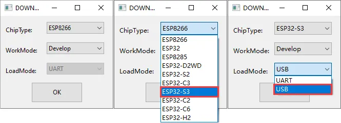
Parameter settings
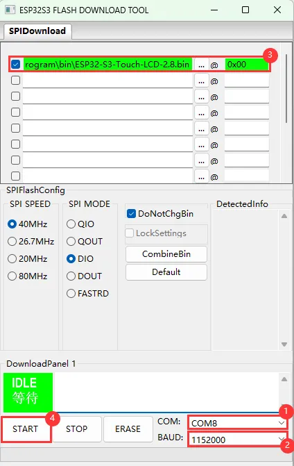
- Select the COM port for the development board
- Set BAUD to the maximum value, 1152000
- Click the "..." button in the row, select the bin file provided by Waveshare, manually enter the flash address given at the top of this page in the field to its right, and select the leftmost checkbox in the row
- Click START to begin flashing
Wait for flashing to complete (this may take some time; please be patient)
Press the reset button and verify the result
Resources
1. Example
2. Hardware Resources
3. Technical Manuals
- ESP32-S3 Chip Official Manuals
4. Software Tools
Debugging Tools
5. Other Resources
Support
Monday-Friday (9:30-6:30) Saturday (9:30-5:30)
Email: services01@spotpear.com
[Tutorial Navigation]
- Product Overview
- Features
- Specifications
- Onboard Resources
- Interface Introduction
- Dimensions
- Working with Arduino
- ESP-IDF
- Firmware Flashing and Erasing
- Resources
- Support