




- sales/support
Google Chat:---
- sales
+86-0755-88291180
- sales01
sales@spotpear.com
- sales02
dragon_manager@163.com
- support
tech-support@spotpear.com
- CEO-Complaints
zhoujie@spotpear.com
- Only Tech-Support
WhatsApp:13246739196
- Purchase/Shipping/Refund
WhatsApp:13424403025
- HOME
- >
- ARTICLES
- >
- Common Moudle
- >
- ESP
ESP32-C6-GEEK User Guide
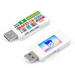
Features
- Adopts Espressif ESP32-C6 as the main chip
- Equipped with a high-performance 32-bit RISC-V processor, clock frequency up to 160MHz
- Built-in 512 KB SRAM, 320 KB ROM, onboard 16MB Flash
- Onboard 1.14inch 240×135 pixels, 65K colors, IPS LCD display
- Integrated 2.4 GHz Wi-Fi 6 and Bluetooth 5 (LE) dual-mode wireless communication
- Onboard TF card slot for external TF card storage of images or files
- Onboard 3PIN UART, 3PIN GPIO, and 4PIN I2C interfaces
- Includes a plastic case and relevant connecting cables
- Provides comprehensive open-source examples and resources, facilitating programming learning and project development
Onboard Resources
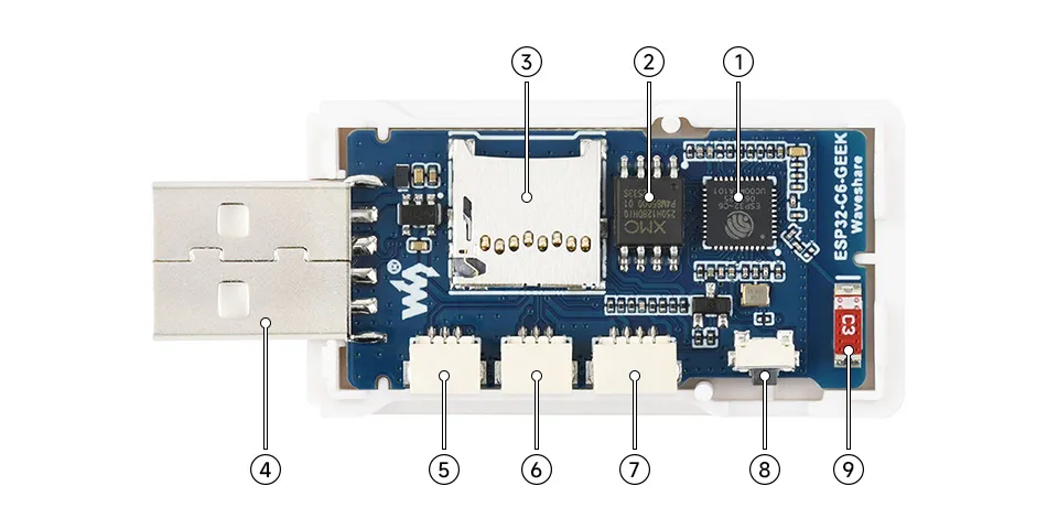
- ESP32-C6 supports Wi-Fi and Bluetooth SoC, operating at 160MHz
- 16MB NOR-Flash for data storage
- TF card slot
- USB-A Port
- UART header can be used to implement a USB-to-serial adapter function
- GPIO header brings out available IO functional pins for easy expansion
- I2C header can be used to test target boards
- BOOT button used for device startup and functional debugging
- Onboard antenna supports 2.4GHz Wi-Fi 6 (802.11 b/g/n) and Bluetooth 5 (LE)
LCD Screen Specifications
| Operating Voltage | 3.3V / 5V | Resolution | 240 × 135 pixels |
|---|---|---|---|
| Communication Interface | 4-wire SPI | Display Size | 24.91 × 14.86 (mm) |
| Display Panel | IPS | Pixel Size | 0.1101 × 0.1035 (mm) |
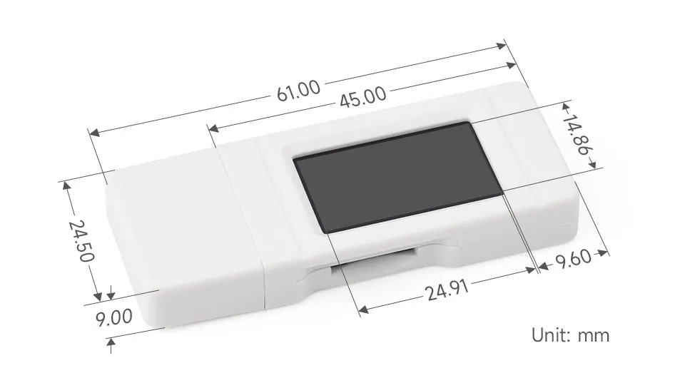
| Controller IC | ST7789 | Product Size | 61.00 × 24.50 (mm) |
SPI Communication Protocol:
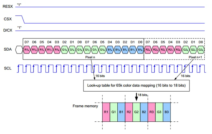
Note: The SPI interface here is specifically designed for screen display, therefore the data line from slave to master (MISO) is omitted.
RESX is the Reset pin; it is pulled low during module power-up and is normally set to 1.
CSX is the slave chip select pin; the chip is enabled only when CS is low
D/CX is the data/command control pin of the chip. When DC = 0, commands are written; when DC = 1, data is written.
SDA is the data transmission pin, specifically for RGB data.
SCL is the SPI communication clock pin.
For SPI communication, data transmission follows a specific timing sequence, which are determined by the combination of clock phase (CPHA) and clock polarity (CPOL):
The level of CPHA determines whether data is captured on the first or second clock transition edge of the serial synchronous clock. When CPHA = 0, data is captured on the first transition edge;
The level of CPOL determines the idle level of the serial synchronous clock. CPOL = 0 means the idle state is low level.
As can be seen from the diagram, data transmission begins at the first falling edge of SCL. One clock cycle transmits 1 bit of data, using SPI0 mode, transmitted bit by bit with the Most Significant Bit (MSB) first and the Least Significant Bit (LSB) last...
Dimensions
Working with Arduino
This chapter includes the following sections, please read as needed:
Arduino Getting Started Tutorial
New to Arduino ESP32 development and looking for a quick start? We have prepared a comprehensive Getting Started Tutorial for you.
- Section 0: Getting to Know ESP32
- Section 1: Installing and Configuring Arduino IDE
- Section 2: Arduino Basics
- Section 3: Digital Output/Input
- Section 4: Analog Input
- Section 5: Pulse Width Modulation (PWM)
- Section 6: Serial Communication (UART)
- Section 7: I2C Communication
- Section 8: SPI Communication
- Section 9: Wi-Fi Basics
- Section 10: Web Server
- Section 11: Bluetooth
- Section 12: LVGL GUI Development
- Section 13: Comprehensive Project
Note: This tutorial uses the ESP32-S3-Zero as a reference example, and all hardware code is based on its pinout. Before you start, we recommend checking the pinout of your development board to ensure the pin configuration is correct.
Setting Up Development Environment
1. Installing and Configuring Arduino IDE
Please refer to the tutorial Installing and Configuring Arduino IDE Tutorial to download and install the Arduino IDE and add ESP32 support.
2. Installing Libraries
To run the demo, you need to install the corresponding library.
You can click this link to download the example package for the ESP32-C6-GEEK development board. The Arduino\libraries directory within the package already includes all the library files required for this tutorial.
| Library/File Name | Description | Version | Installation Method |
|---|---|---|---|
| ESP32-BLE-Keyboard-master | ESP32 Bluetooth Keyboard Library | v0.3.2 | Manual Install |
| PubSubClient | MQTT message subscription and publishing library | v2.8.0 | Via Library Manager or Manual Install |
| JPEGDecoder | JPEG Image Decoder library | v2.0.0 | Via Library Manager or Manual Install |
| OneButton | Single Button events handling library | v2.5.0 | Via Library Manager or Manual Install |
| BME68x Sensor library | BME68x Sensor driver library | v1.1.40406 | Via Library Manager or Manual Install |
| ArduinoJson | Lightweight JSON library | v7.2.1 | Via Library Manager or Manual Install |
There are strong dependencies between versions of LVGL and its driver libraries. For example, a driver written for LVGL v8 may not be compatible with LVGL v9. To ensure stable reproduction of the examples, it is recommended to use the specific versions listed in the table above. Mixing different library versions may cause compilation failures or runtime exceptions.
Installation Steps:
Unzip the downloaded example package.
Copy all folders (Arduino_DriveBus, GFX_Library_for_Arduino, etc.) in the
Arduino\librariesdirectory to the Arduino library folder.INFOThe path to the Arduino libraries folder is typically:
c:\Users\<Username>\Documents\Arduino\libraries.You can also locate it within the Arduino IDE via File > Preferences, by checking the "Sketchbook location". The library folder is the
librariesfolder under this path.For other installation methods, please refer to: Arduino Library Management Tutorial.
3. Other Tips
You need to select and configure the development board for ESP32-C6-GEEK.
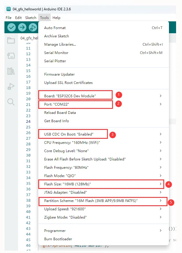
- Select the ESP32C6 Dev Module for ESP32-C6-GEEK.
- Select the USB port.
- The ESP32-C6-GEEK uses the ESP32-C6 native USB interface, not a UART-to-USB bridge. For serial communication:
The
printf()function can be used directly;To use the
Serial.println()function, additional configuration is required: enable the "USB CDC On Boot" option in the IDE's Tools menu, or declare anHWCDCobject in your code to handle USB serial communication.
- Select 16MB Flash
- Select a Partition Table of the appropriate size
Example
The Arduino examples are located in the Arduino/examples directory of the example package.
| Demo | Basic Program Description | Dependency Library |
|---|---|---|
| 01_OneButton | Button interaction and LCD display | OneButton |
| 02_ADC_Read | ADC sampling | |
| 03_IIC_BME68X_Sensor | Driving I2C module | BME68x Sensor libraryXPowersLib |
| 04_UART0 | Serial communication | |
| 05_LCD_Button | Button operation to switch images, control backlight | OneButton |
| 06_LCD_Time | Display date and time on LCD | |
| 07_SD_Test | Perform file operations (create, read, update, delete) on TF card | |
| 08_SD_LCD | Read JPEG images from TF card and display them on screen | JPEGDecoder |
| 09_BLE_LCD | ESP32-C6 interacts with BLE and LCD, acts as a BLE server to send/receive data and display it on LCD | ESP32-BLE-Keyboard-master |
| 10_BLE_UART | ESP32-C6 interacts with BLE, acts as a BLE server to send/receive data and uses UART to display message content | ESP32-BLE-Keyboard-master |
| 11_BLE_Keyboard | Simulate a BLE Keyboard | ESP32-BLE-Keyboard-master |
| 12_WIFI_AP_LCD | Interacts with Wi-Fi and LCD, acts as a Wi-Fi Access Point to communicate with clients and display on LCD | |
| 13_WIFI_TCP_Client | Interacts with Wi-Fi and LCD, connects to Wi-Fi, then attempts to connect to a server, sends/receives data and displays on LCD | |
| 14_WIFI_TCP_Server | Interacts with Wi-Fi and LCD, acts as a Wi-Fi Server, receives client data and displays on LCD | |
| 15_WIFI_Web_Server | Interacts with Wi-Fi and LCD, acts as a Wi-Fi Access Point Server, handles client requests | |
| 16_MQTT_sub_pub | Interacts with Wi-Fi and LCD, acts as a Wi-Fi Access Point Server, handles client requests | ArduinoJson, PubSubClient |
| 17_MQTT_BLE_Keyboard | Integrates BLE Keyboard, Wi-Fi, and MQTT, controls LCD display | ArduinoJson, PubSubClient, ESP32-BLE-Keyboard-master |
01_OneButton
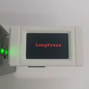
This example demonstrates how to use the ESP32-C6-GEEK's Boot button as a multi-function button, capable of performing different actions such as single-click, double-click, or long-press. It is suitable for learning ESP32-C6 button interaction and LCD display. You can observe LCD changes through button operations to test its reliability.
Code
01_OneButton.ino
Code Analysis
Button event binding:
button.attachLongPressStart(LongPressStart, &button);button.attachClick(Click, &button);button.attachDoubleClick(DoubleClick, &button);button.setLongPressIntervalMs(1000);Continuous monitoring:
void loop() {// keep watching the push button:button.tick();delay(10);}Button event callback:
void LongPressStart(void *oneButton){LCD_Clear(BLACK);Paint_DrawString_EN(50, 50, "LongPress", &Font24, BLACK, RED);}void Click(void *oneButton){LCD_Clear(BLACK);Paint_DrawString_EN(75, 50, "Click", &Font24, BLACK, YELLOW);}void DoubleClick(void *oneButton){LCD_Clear(BLACK);Paint_DrawString_EN(35, 50, "DoubleClick", &Font24, BLACK, BLUE);}
02_ADC_Read
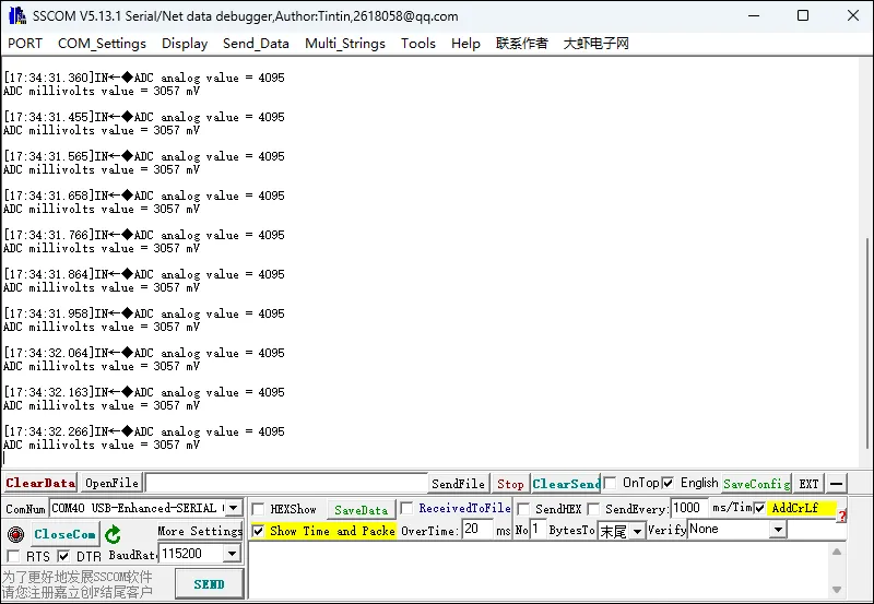
This example uses the GPIO interface of the ESP32-C6-GEEK to perform ADC sampling, reading voltages within the 3.3V range. Pay attention to common grounding and do not exceed the measurement range during use. It is suitable for learning analog input on the ESP32-C6. You can read analog values from specific pins, observe changes, and test stability.
Hardware Connection
Connect both ends of an SH1.0 3PIN cable to the development board and the voltage source under test.
- The pin connected to GPIO6 on the development board is used to read the measured voltage.
- The GND pin on the development board (the GND of the I2C or UART interface can be used) is connected to the GND pin of the voltage source under test, ensuring a common ground connection.
Code
02_ADC_Read.ino
Code Analysis
Initialize the backlight control pin to a low level.
Enable serial communication, set the baud rate to 115200.
Set the ADC resolution to 12-bit.
void setup() {analogWrite(DEV_BL_PIN,0);Serial.begin(115200); //The serial port is initially configuredanalogReadResolution(12); //Set ADC resolution to 12 bits (0-4096)}Define variables to store the raw ADC value and the voltage value.
Read the raw ADC value and the voltage value from the specified pin.
Output the ADC value via the serial port.
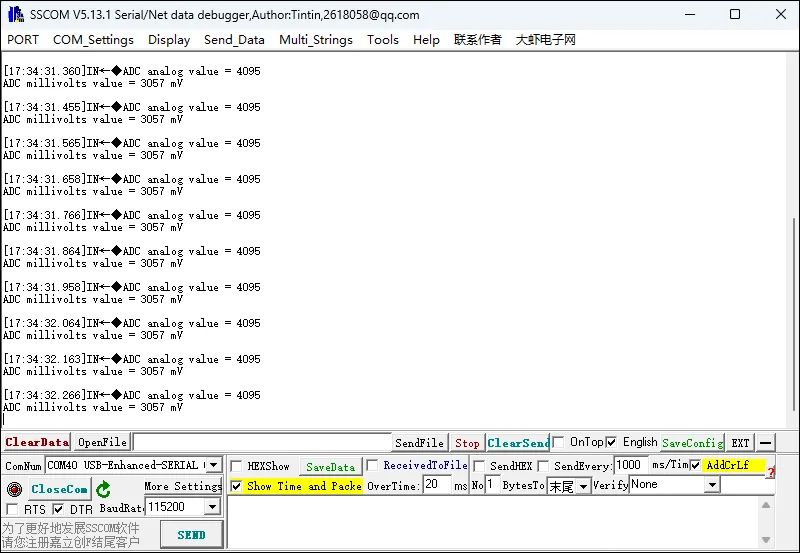
void loop() {// Define two variables to hold the original value and the voltage value (millivolts) collected by the ADCint analogOriginalValue = 0;int analogVoltsValue = 0;analogOriginalValue = analogRead(ADC1_CHANNEL_0); // Read the ADC raw valueanalogVoltsValue = analogReadMilliVolts(ADC1_CHANNEL_0); // Read ADC voltage values (millivolt range)// Upload read ADC values:Serial.printf("ADC analog value = %d\n",analogOriginalValue);Serial.printf("ADC millivolts value = %d mV\n",analogVoltsValue);delay(3000);}
03_IIC_BME68X_Sensor
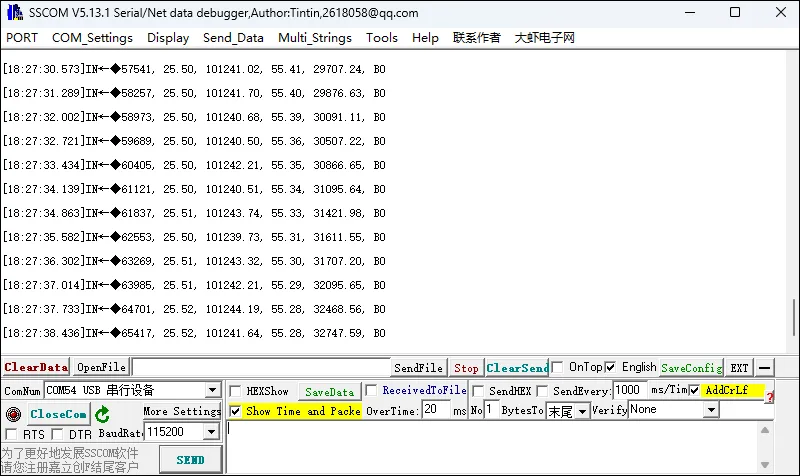
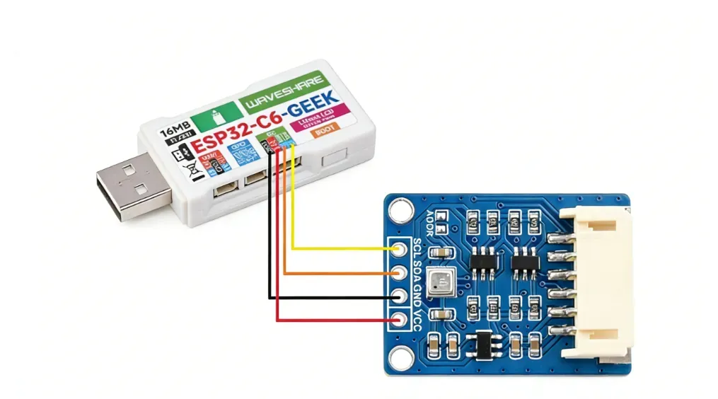
This example uses the I2C hardware interface of the ESP32-C6-GEEK to drive an I2C module. The example demonstrates using a BME680 sensor, printing data output via the serial port. It is suitable for learning how the ESP32-C6 interacts with BME68X sensors. You can set pins and communication modes, read various data, and test compatibility and stability.
Hardware Connection
Code
03_IIC_BME68X_Sensor.ino
Code Analysis
Use
analogWriteto set the backlight control pin PIN_BL to 0, turning off the backlight.Use
Wire.begin(PIN_SDA, PIN_SCL)to initialize I2C communication (the commentedSPI.begin()indicates SPI mode is also possible but is not enabled here).Initialize serial communication, set the baud rate to 115200.
Wait for the serial port connection to be ready.
Initialize the BME68X sensor according to the configured communication method (I2C here). If an error or warning occurs during initialization, corresponding information will be output via serial.
Set the sensor's temperature, pressure, and humidity measurement configurations, and configure the heater.
Output a header row for the data via serial, including timestamp, temperature, pressure, humidity, gas resistance, and status.
setup() {{analogWrite(PIN_BL,0);Wire.begin(PIN_SDA, PIN_SCL); //I2C mode//SPI.begin(); //SPI modeSerial.begin(115200);delay(100);Serial.println(PIN_SDA);Serial.println(PIN_SCL);while (!Serial)delay(10);/* initializes the sensor based on SPI library *///bme.begin(PIN_CS, SPI); //SPI modebme.begin(ADD_I2C, Wire); //I2C modeif(bme.checkStatus()){if (bme.checkStatus() == BME68X_ERROR){Serial.println("Sensor error:" + bme.statusString());return;}else if (bme.checkStatus() == BME68X_WARNING){Serial.println("Sensor Warning:" + bme.statusString());}}/* Set the default configuration for temperature, pressure and humidity */bme.setTPH();/* Set the heater configuration to 300 deg C for 100ms for Forced mode */bme.setHeaterProf(300, 100);Serial.println("TimeStamp(ms), Temperature(deg C), Pressure(Pa), Humidity(%), Gas resistance(ohm), Status");}
04_UART0
This example opens the UART0 serial port on the ESP32-C6-GEEK. By opening a serial debug assistant, serial communication can be performed. It is suitable for learning serial communication on the ESP32-C6, receiving data and outputting it.
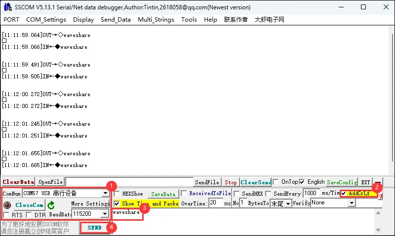
Hardware Connection
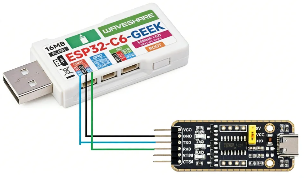
Code
04_UART0.ino
Code Analysis
Check if there is data available to read from the serial port. If data is available, enter a loop to process the input data.
Create a character array
bufferto store input data and a variablebufferSizeto record the amount of data in the buffer.In the loop, read one character at a time and store it in the buffer, while incrementing the buffer size.
When the buffer is full (reaches the array size) or a newline character is read, output the data in the buffer via serial, then delay for 10 milliseconds.
Finally, reset the buffer size to 0 and use the
memsetfunction to clear the buffer, preparing for the next input.void loop() {if (Serial.available()) {char buffer[256]; // Buffer to store input datasize_t bufferSize = 0; // Current size of data in bufferwhile (Serial.available() > 0) {char input = Serial.read();buffer[bufferSize++] = input; // Store input in buffer// Check if the buffer is full, or a newline character is receivedif (bufferSize >= sizeof(buffer) || input == '\n') {// Send the entire buffer via Serial2Serial.println(buffer);delay(10);// Reset buffer and size for the next inputbufferSize = 0;memset(buffer, 0, sizeof(buffer));}}}}
05_LCD_Button
This example uses the Boot button of the ESP32-C6-GEEK to achieve a short press to turn on the LCD and switch to the next image, and a long press to turn off the LCD. It is suitable for learning button interaction and LCD image display on the ESP32-C6. You can switch images and control the backlight through button operations to test stability.
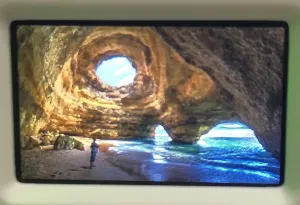
Code
05_LCD_Button.ino
Code Analysis
When the button is clicked, this function is called. It switches the display to different images (
gImage_pic1,gImage_pic2,gImage_pic3) based on differentclickvalues:void Click(void *oneButton){LCD_SetBacklight(1000);Paint_NewImage(LCD_WIDTH, LCD_HEIGHT, 0, BLACK);click++;if(click >= 4)click = 1;switch(click){case 1:Paint_DrawImage(gImage_pic1, 0, 0, 135, 240);break;case 2:Paint_DrawImage(gImage_pic2, 0, 0, 135, 240);break;case 3:Paint_DrawImage(gImage_pic3, 0, 0, 135, 240);break;}}
06_LCD_Time
This example uses the ESP32-C6-GEEK to connect to Wi-Fi, obtain the current time, and display the time and date on both the LCD and a serial debug assistant. It is suitable for learning Wi-Fi connection and time synchronization on the ESP32-C6. You can connect to a specific network, synchronize time, display the date and time on the LCD, and test stability and accuracy.
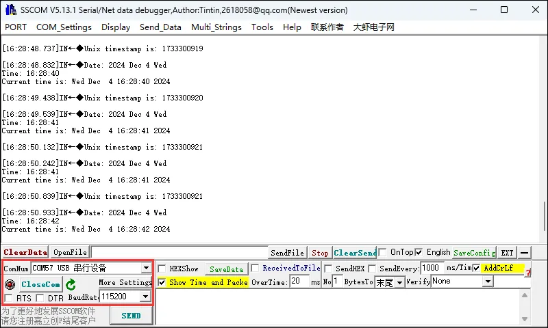
Additional Preparation
Use a PC to open a hotspot. Set the network band to "Any available frequency". Modify ssid and password to the Wi-Fi name and password you want to connect to. utcOffsetInSeconds is the time zone for which we need to obtain the time. For example, Beijing, UTC+8 (East 8th zone), is 8 * 60 *60=28800.
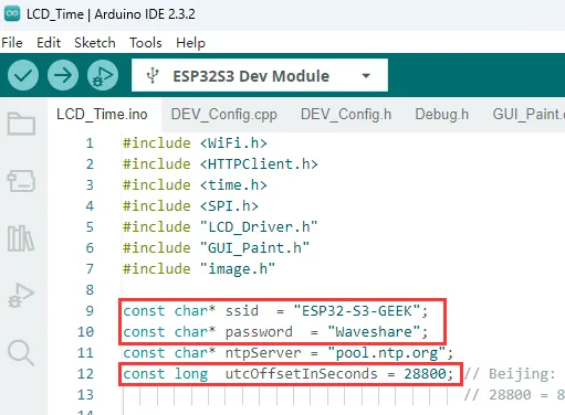
Note: When the ESP32-C6-GEEK operates in STA mode and connects to the same Wi-Fi network as the PC, the Wi-Fi network the ESP32-C6-GEEK connects to must have a 2.4GHz band. If there is no 2.4GHz band, set the network band to "Any available frequency". Here, we directly choose "Any available frequency".
Code
06_LCD_Time.ino
Code Analysis
Display "Wifi Connecting..." on the LCD to indicate that the device is attempting to connect to Wi-Fi. Initiate the connection process using
WiFi.begin(ssid, password)with the specified network name and password, and enter a loop to wait for a successful connection. During this process, print "Connecting to WiFi..." to the serial monitor every 1000 milliseconds to inform the user of the connection progress. Once the connection is successful, clear the LCD screen and display "Wifi Connected", preparing for subsequent network-dependent operations.void setup() {Serial.begin(115200);Config_Init();LCD_Init();LCD_SetBacklight(100);Paint_NewImage(LCD_WIDTH, LCD_HEIGHT, 90, WHITE);Paint_SetRotate(90);LCD_Clear(BLACK);delay(1000);while (!Serial);Paint_DrawString_EN(20, 50, "Wifi Connecting...", &Font20, BLACK, GREEN);WiFi.begin(ssid, password);while (WiFi.status() != WL_CONNECTED) {delay(1000);Serial.println("Connecting to WiFi...");}LCD_Clear(BLACK);Paint_DrawString_EN(20, 50, "Wifi Connected", &Font20, BLACK, GREEN);Serial.println("Connected to WiFi");//Acquisition timeconfigTime(utcOffsetInSeconds, 0, ntpServer);while (!time(nullptr)) {delay(1000);Serial.println("Waiting for time sync...");}LCD_Clear(BLACK);Serial.println("Time synced successfully");}
07_SD_Test
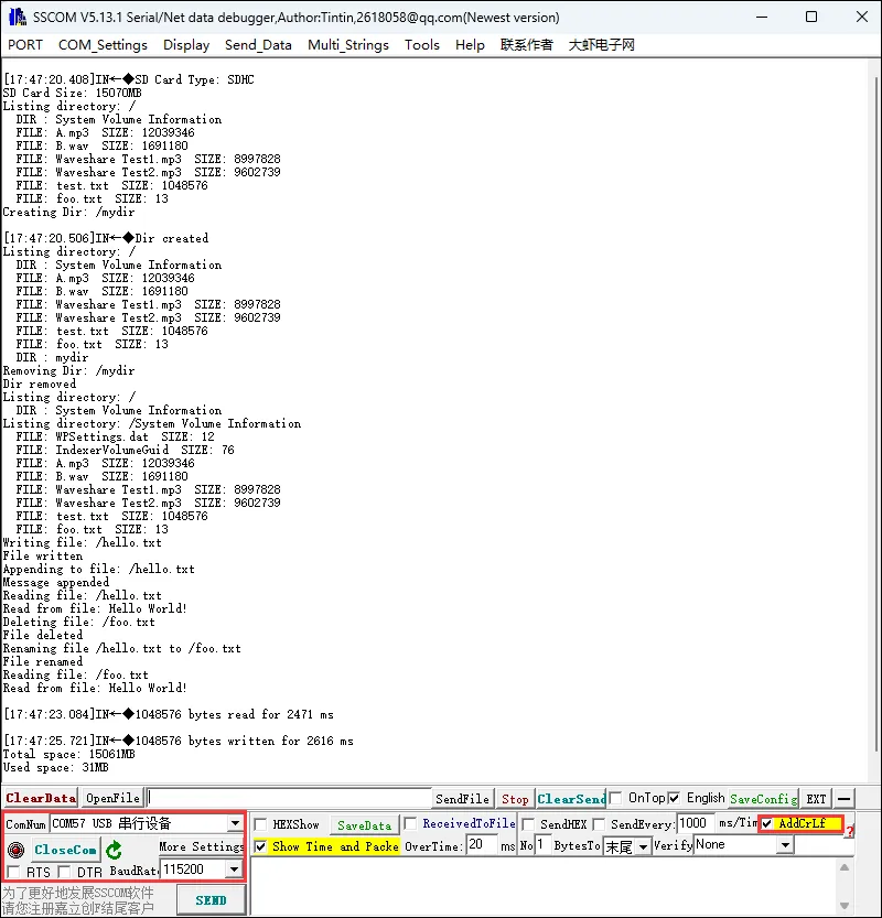
This example uses the TF card slot of the ESP32-C6-GEEK. Insert a TF card into the slot and open a serial debug assistant. You will see the ESP32-C6-GEEK performing file operations (create, read, update, delete) on the TF card. It is suitable for learning TF card interaction on the ESP32-C6, performing various file operations, and testing stability and reliability.
Code
07_SD_Test.ino
Code Analysis
Initialize serial communication, start the HSPI bus and set the clock divider, then attempt to initialize the TF card connected to specific pins. If successful, determine the TF card type and display its capacity. After that, perform a series of tests on file system operations on the TF card, such as listing directories, creating and deleting directories, reading and writing files, renaming files, and testing read/write performance, while outputting the total space and used space of the TF card.
void setup() {Serial.begin(115200);while (!Serial){delay(10);}#ifdef REASSIGN_PINSSPI.begin(sck, miso, mosi, cs);if (!SD.begin(cs)) {#elseif (!SD.begin()) {#endifSerial.println("Card Mount Failed");return;}uint8_t cardType = SD.cardType();if (cardType == CARD_NONE) {Serial.println("No TF card attached");return;}Serial.print("TF Card Type: ");if (cardType == CARD_MMC) {Serial.println("MMC");} else if (cardType == CARD_SD) {Serial.println("SDSC");} else if (cardType == CARD_SDHC) {Serial.println("SDHC");}else{Serial.println("UNKNOWN");}uint64_t cardSize = SD.cardSize() / (1024 * 1024);Serial.printf("TF Card Size: %lluMB\n", cardSize);listDir(SD, "/", 0);createDir(SD, "/mydir");listDir(SD, "/", 0);removeDir(SD, "/mydir");listDir(SD, "/", 2);writeFile(SD, "/hello.txt", "Hello ");appendFile(SD, "/hello.txt", "World!\n");readFile(SD, "/hello.txt");deleteFile(SD, "/foo.txt");renameFile(SD, "/hello.txt", "/foo.txt");readFile(SD, "/foo.txt");testFileIO(SD, "/test.txt");Serial.printf("Total space: %lluMB\n", SD.totalBytes() / (1024 * 1024));Serial.printf("Used space: %lluMB\n", SD.usedBytes() / (1024 * 1024));}
08_SD_LCD
This example uses the TF card slot of the ESP32-C6-GEEK to read images from the TF card. After saving photo images to the TF card, insert the TF card into the slot. The ESP32-C6-GEEK can read the photos from the TF card and display them on the LCD. It is suitable for learning the interaction between the ESP32-C6, TF card, and TFT screen. You can read JPEG images from the TF card and display them on the screen, testing stability and reliability.
TF Card Preparation
Use a card reader to save the photos from the path .\ESP32-C6-GEEK-Demo\Arduino\pic onto the TF card, or save your own photos. For optimal display, modify the image size to 240×135.
Hardware Connection
Connect both ends of an SH1.0 3PIN cable to the development board and the voltage source under test.
- The pin connected to GPIO6 on the development board is used to read the measured voltage.
- The GND pin on the development board (the GND of the I2C or UART interface can be used) is connected to the GND pin of the voltage source under test, ensuring a common ground connection.
Code
08_SD_LCD.ino
Code Analysis
Decode the JPEG image and draw it centered on the TFT display.
void renderJPEG() {uint16_t *pImg;uint16_t mcu_w = JpegDec.MCUWidth;uint16_t mcu_h = JpegDec.MCUHeight;uint32_t jpeg_width = JpegDec.width;uint32_t jpeg_height = JpegDec.height;Serial.print("270-degree rotation: ");Serial.print(jpeg_width);Serial.print(" x ");Serial.println(jpeg_height);uint16_t rotated_width = jpeg_height; // 135uint16_t rotated_height = jpeg_width; // 240uint16_t x_pos = (LCD_WIDTH - rotated_width) / 2;uint16_t y_pos = (LCD_HEIGHT - rotated_height) / 2;Paint_Clear(WHITE);while (JpegDec.read()) {pImg = JpegDec.pImage;uint16_t mcu_x = JpegDec.MCUx * mcu_w;uint16_t mcu_y = JpegDec.MCUy * mcu_h;for (int y = 0; y < mcu_h; y++) {for (int x = 0; x < mcu_w; x++) {uint16_t orig_x = mcu_x + x;uint16_t orig_y = mcu_y + y;if (orig_x >= jpeg_width || orig_y >= jpeg_height) continue;// Rotation formula:uint16_t screen_x = x_pos + (jpeg_height - orig_y - 1);uint16_t screen_y = y_pos + orig_x;if (screen_x < LCD_WIDTH && screen_y < LCD_HEIGHT) {uint16_t color = pImg[x + y * mcu_w];Paint_SetPixel(screen_x, screen_y, color);}}}}JpegDec.abort();}
09_BLE_LCD
This example enables Bluetooth BLE on the ESP32-C6-GEEK. Use a mobile phone to open a Bluetooth debug assistant, connect to the ESP32-C6-GEEK, and perform BLE communication with the phone. Messages sent and received are displayed on the LCD. It is suitable for learning how the ESP32-C6 interacts with BLE and LCD, acting as a BLE server to send/receive data and display it on the LCD, testing stability and reliability.
Code
09_BLE_LCD.ino
Operation Result
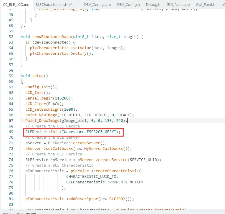
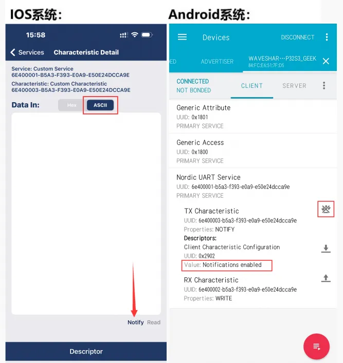
Waveshare_ESP32C6_GEEK in BLEDevice::init("Waveshare_ESP32C6_GEEK") is the Bluetooth name.
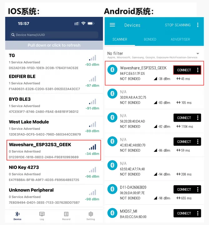
Use the mobile phone's Bluetooth debug assistant to scan and connect to the device.
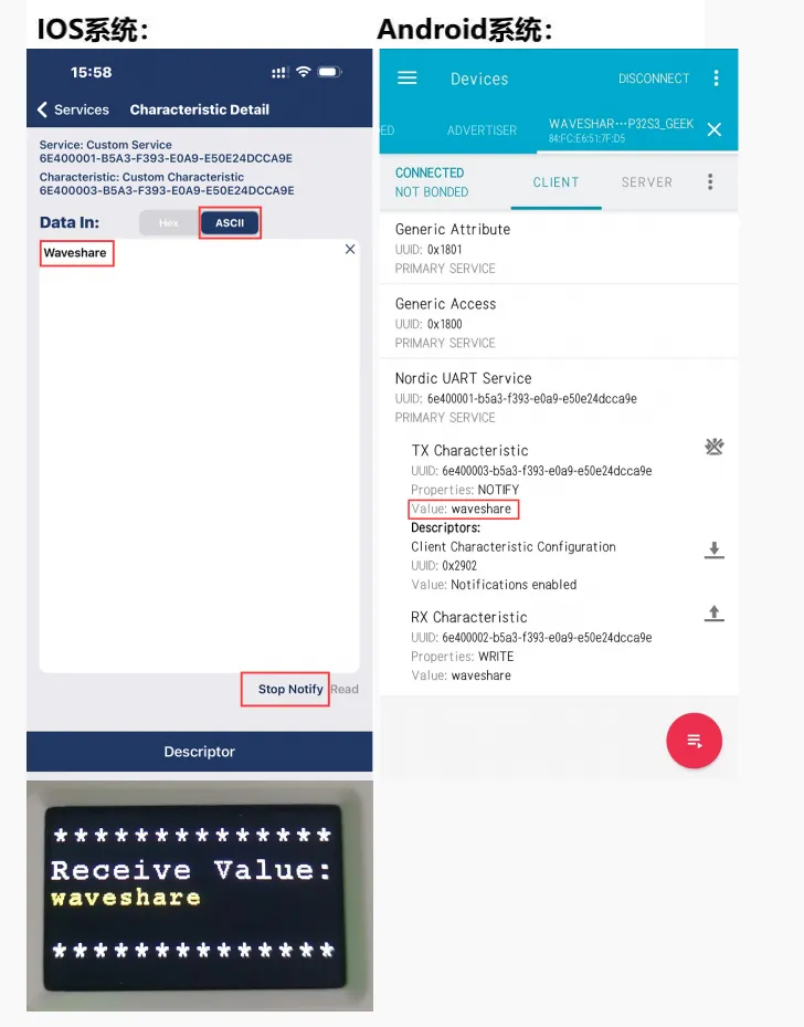
Use the mobile Bluetooth debug assistant to send a Bluetooth message to the ESP32-C6-GEEK. Upon receiving the message, the ESP32-C6-GEEK will display it on the LCD, and the serial debug assistant will print the message content.
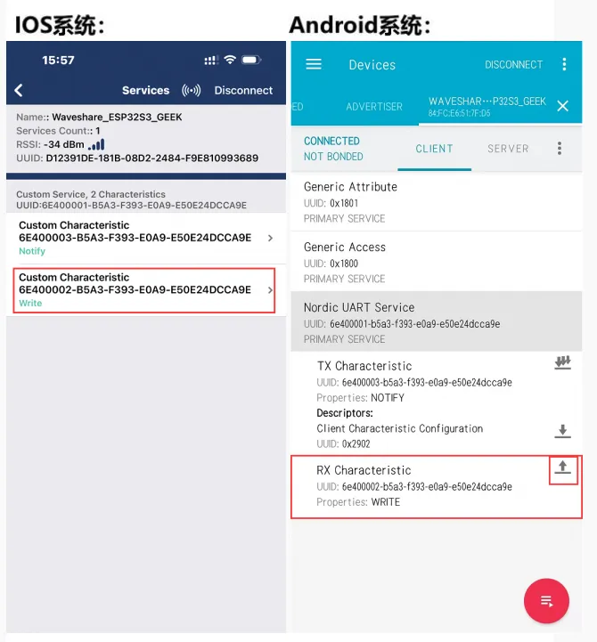
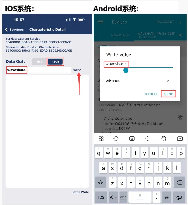
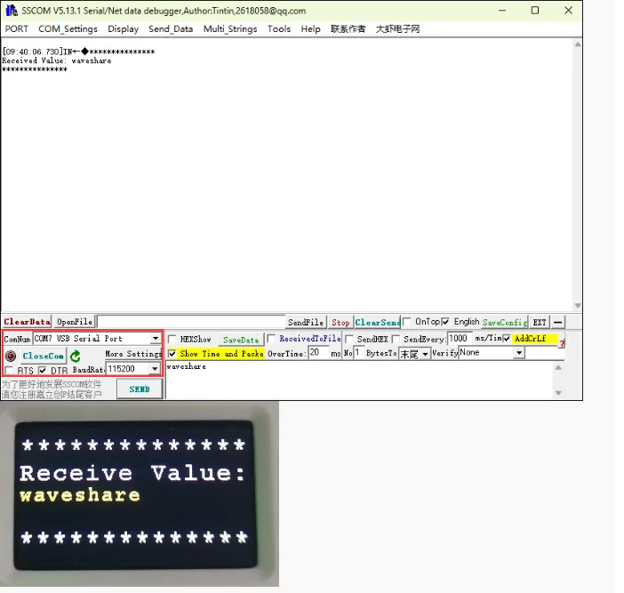
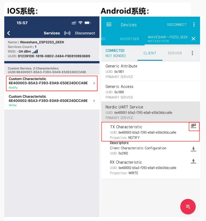
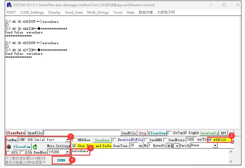
In the mobile Bluetooth debug assistant, open the receive settings. Connect the ESP32-C6-GEEK to a PC using a USB to UART adapter. Open a serial debug assistant on the PC. Send a serial message converted to a Bluetooth message to the phone. Note: When sending, check "AddCrLf". The sent message content will be displayed on the LCD. Observe on the mobile phone whether the Bluetooth message is received.
10_BLE_UART
This example enables Bluetooth BLE on the ESP32-C6-GEEK. Use a mobile phone to open a Bluetooth debug assistant, connect to the ESP32-C6-GEEK, and perform BLE communication with the phone. Messages sent and received are displayed via the serial port. The operation is the same as 09_BLE_LCD, but the LCD is not enabled. It uses UART to display message content, significantly reducing power consumption. For the operation procedure, please see 09_BLE_LCD.
11_BLE_Keyboard
- This example allows the ESP32-C6-GEEK to be used as a Bluetooth keyboard. Connect the ESP32-C6-GEEK to a PC via Bluetooth to perform a series of single-key or key combination operations. It is suitable for simulating a BLE keyboard with the ESP32-C6-GEEK, sending text and key commands, and testing stability and reliability.
- Press the Boot button to reboot and exit the program.
Code
11_BLE_Keyboard.ino
Code Analysis
Bluetooth name
BleKeyboard bleKeyboard("ESP32-C6-GEEK", "Waveshare", 100);
Check if the Bluetooth keyboard is connected. If connected:
- Output the prompt "Sending 'Waveshare'..." to the serial port, then use the
printmethod to send the string "Waveshare". - Output the prompt "Sending Enter key..." to the serial port, then use the
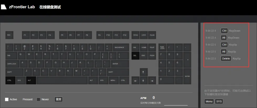
writemethod to send the Enter key (KEY_RETURN). - Output the prompt "Sending Ctrl+Alt+Delete..." to the serial port. Press the left Ctrl, left Alt, and Delete keys in sequence, delay for 100 milliseconds, then release all keys.
- Output the prompt "Waiting 5 seconds..." to the serial port, then delay for 5000 milliseconds, waiting for the next loop.
  void loop() {
  if(bleKeyboard.isConnected()) {
    Serial.println("Sending 'Waveshare'...");
    bleKeyboard.print("waveshare");

    delay(500);

    Serial.println("Sending Enter key...");
    bleKeyboard.write(KEY_RETURN);

    delay(500);

    Serial.println("Sending Ctrl+Alt+Delete...");
    bleKeyboard.press(KEY_LEFT_CTRL);
    bleKeyboard.press(KEY_LEFT_ALT);
    bleKeyboard.press(KEY_DELETE);
    delay(100);
    bleKeyboard.releaseAll();
  }

  Serial.println("Waiting 5 seconds...");
  delay(5000);
}
Operation Result
- Use the PC to turn on Bluetooth, scan and connect to the device.
- Once successfully connected, a series of keyboard operations (output "Waveshare", Ctrl+Alt+Delete) will be performed every 5 seconds.
- Press the Boot button to reboot and exit the program.
- You can view the values of individual keys in the
BleKeyboard.hfile located in thelibrariesfolder.
12_WIFI_AP_LCD
This example enables the Wi-Fi AP mode on the ESP32-C6-GEEK. After a PC connects to its Wi-Fi, you can log in to the IP address and control the LCD display of the ESP32-C6-GEEK via a web interface to show images. It is suitable for learning how the ESP32-C6-GEEK interacts with Wi-Fi and LCD, acting as a Wi-Fi Access Point to communicate with clients and display content on the LCD, testing stability and reliability.
Code
12_WIFI_AP_LCD.ino
Code Analysis
Initialize related configurations and the LCD display.
Call
WIFI_AP_Init()to initialize the Wi-Fi Access Point.void setup(){Config_Init();LCD_Init();Serial.begin(115200);LCD_SetBacklight(100);Paint_NewImage(LCD_WIDTH, LCD_HEIGHT, 90, WHITE);Paint_SetRotate(90);LCD_Clear(0x000f);WIFI_AP_Init();}Monitor if any client connects to the server via
WiFiClient client = server.available();.Call the
WIFI_LCD_Control(client)function to handle the connected client. This may perform operations related to LCD display, with specific functionality depending on the implementation of that function.void loop(){WiFiClient client = server.available(); // listen for incoming clientsWIFI_LCD_Control(client);}
Operation Result
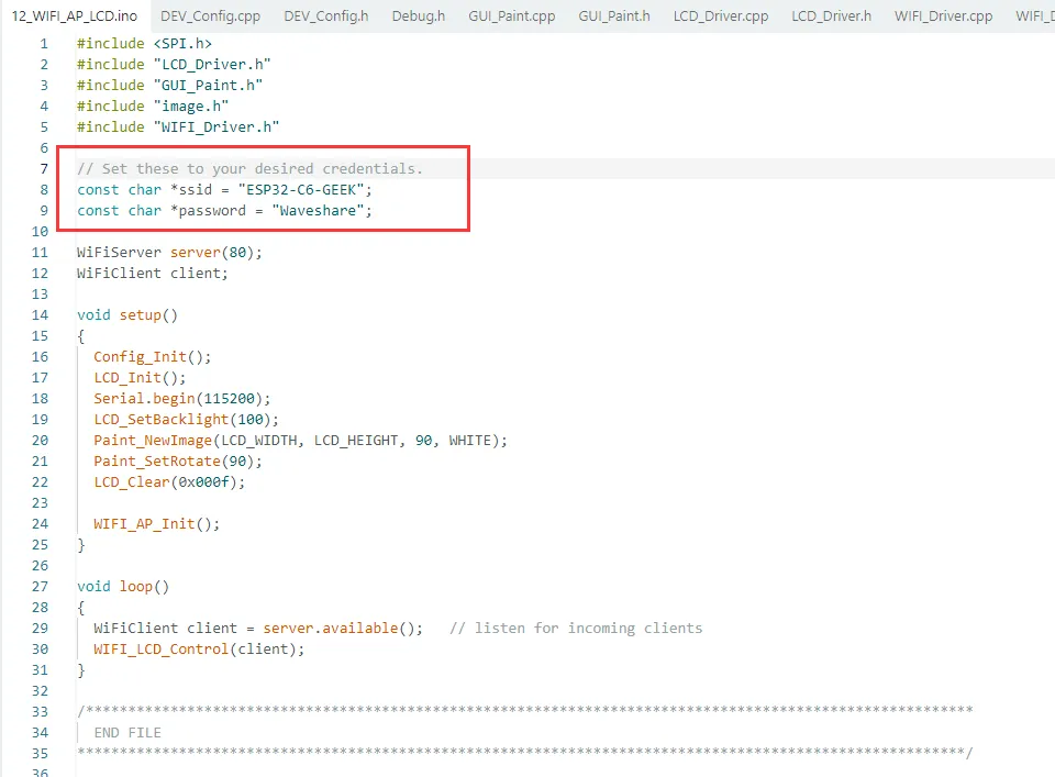
The ssid is the AP name (ESP32-C6-GEEK) created by the ESP32-C6-GEEK, and the password is the password (Waveshare) to connect to the AP.
- Use a PC to connect to the AP of the ESP32-C6-GEEK, and enter the password Waveshare.
- If the program is successfully flashed but the PC cannot detect the Wi-Fi, power cycle the development board and try again.
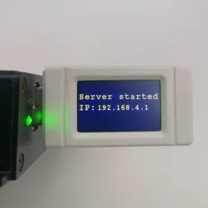
- The LCD will display the IP address of the HTTP server.
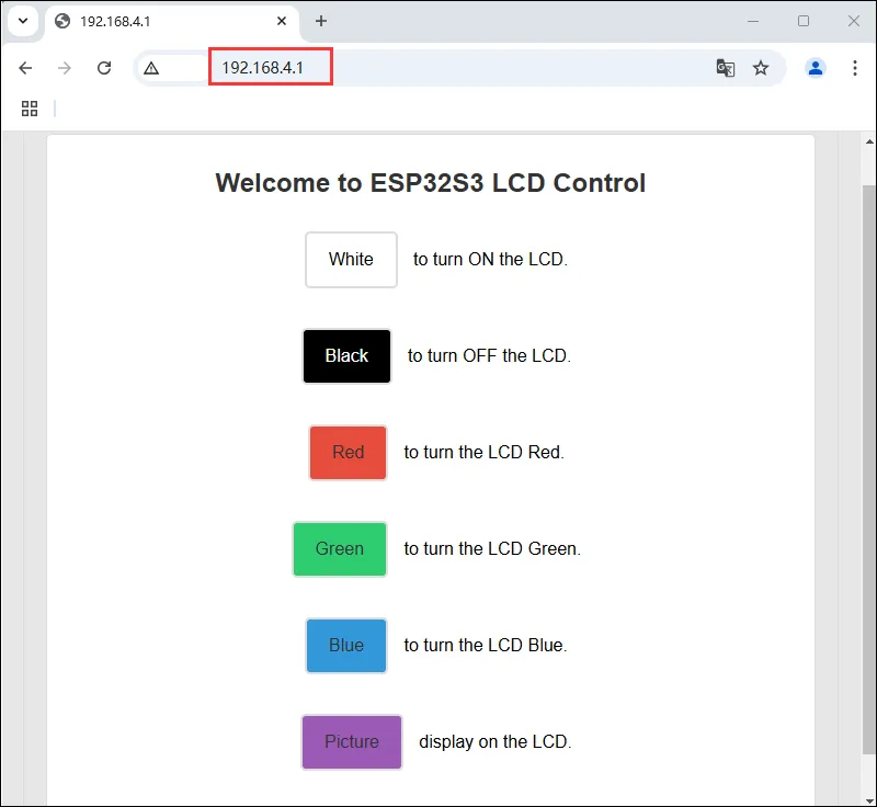
Use a browser to log in to the IP: 192.168.4.1. Control the LCD of the ESP32-C6-GEEK via buttons on the server. Press different buttons and observe the changes on the LCD. For more LCD display functions, refer to the LCD Program Description.
13_WIFI_TCP_Client
This example enables the STA mode of Wi-Fi on the ESP32-C6-GEEK. After connecting to the same Wi-Fi network as a PC or mobile phone, it acts as a TCP Client to access a TCP Server created by the PC or phone, establishes TCP communication with them, and displays the received content on the LCD. It is suitable for learning the interaction between the ESP32-C6-GEEK, Wi-Fi, and LCD. After connecting to Wi-Fi, it attempts to connect to a server, sends/receives data, and displays it on the LCD, testing stability and reliability.
Code Modification
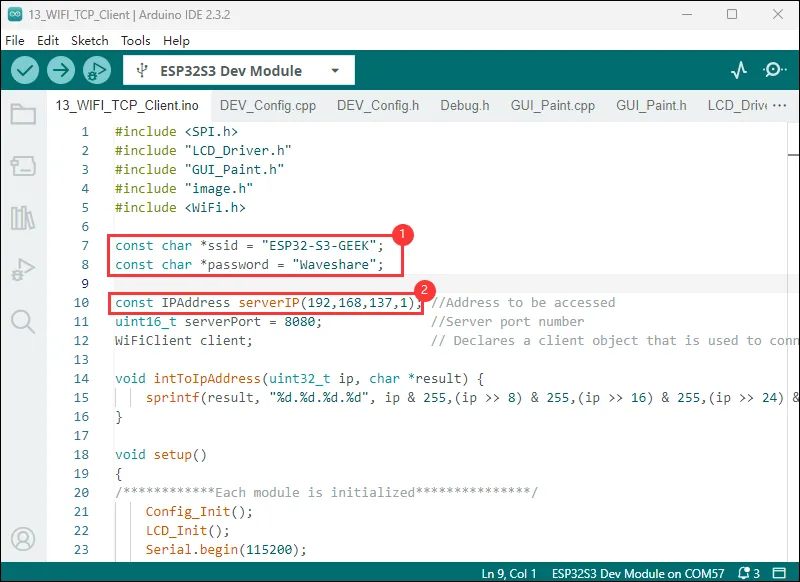
- Use a PC to open a hotspot, set the network band to "Any available frequency". Ensure the
ssidandpasswordin the program match the Wi-Fi name and password you want to connect to. - Download the Network Debug Assistant, and modify it to your local IP address (the following 192.168.137.1 is an example IP address).
Code
13_WIFI_TCP_Client.ino
Code Analysis
Use the
sprintffunction to convert the passed IP address integer into a string in dotted-decimal format and store it in the character array pointed to by theresultpointer.void intToIpAddress(uint32_t ip, char *result) {sprintf(result, "%d.%d.%d.%d", ip & 255,(ip >> 8) & 255,(ip >> 16) & 255,(ip >> 24) & 255);}
Operation Result
- The LCD screen shows an attempt to connect, and after a few moments it shows that it is connected
- Modify the
NetAssistparameters: set the protocol type to TCP Server, the local IP address to match the one in the program, and the local port to 8080. Click "Open" to establish a connection and TCP communication with the ESP32-C6-GEEK (TCP Client).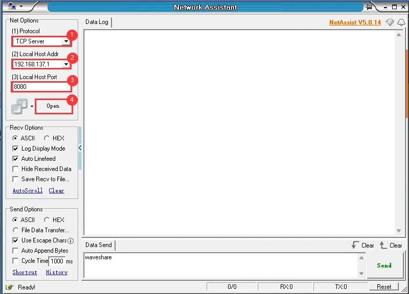
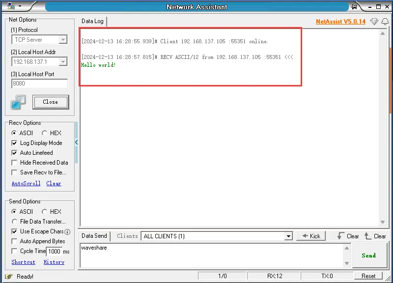
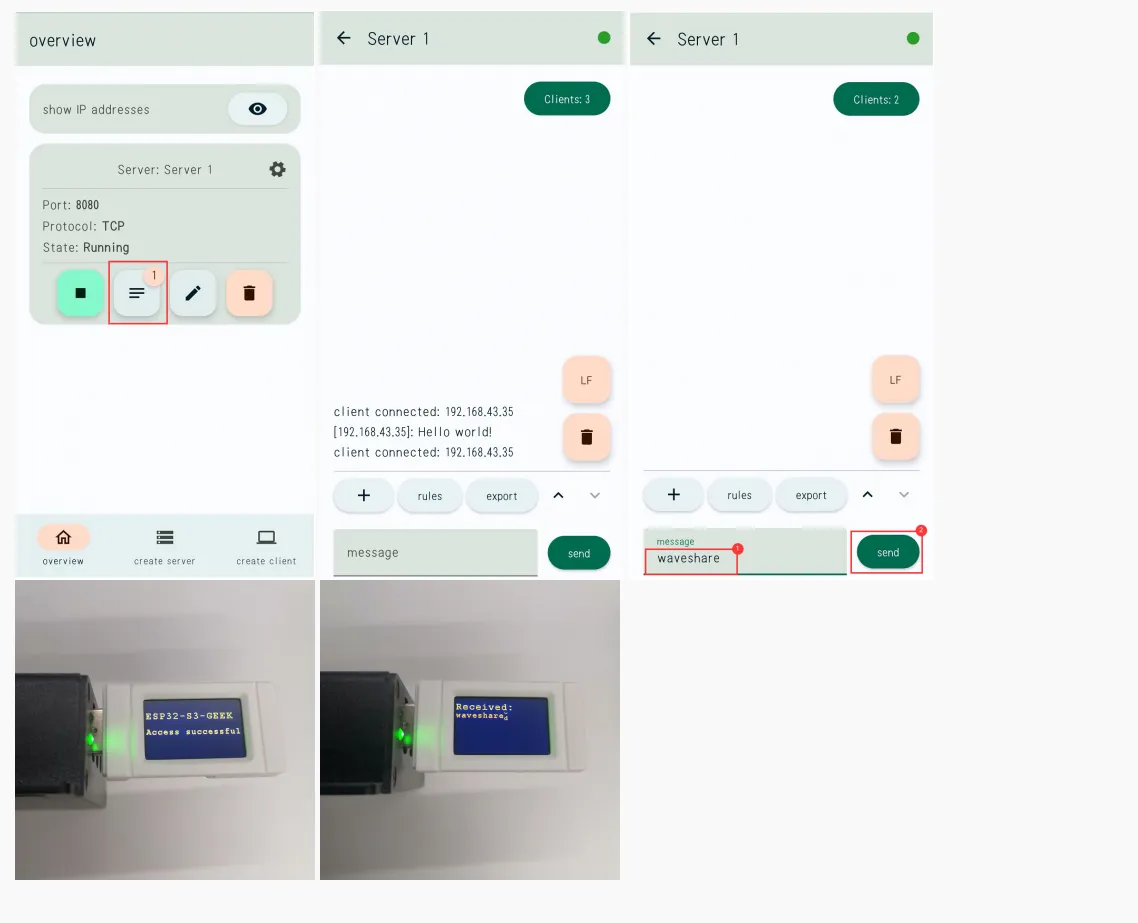
- After a successful connection, the TCP Server will receive the TCP message "Hello world" sent by the ESP32-C6-GEEK, and the LCD will display "Access successful".
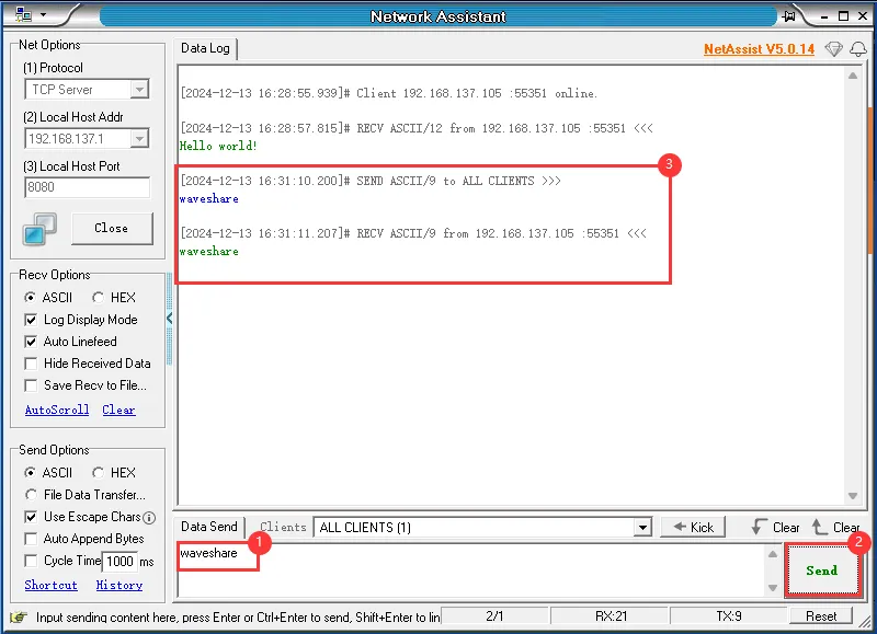
- Send a TCP message from the PC-side TCP Server to the ESP32-C6-GEEK. If sent successfully, the ESP32-C6-GEEK, acting as a TCP Client, will receive the message and display its content on the LCD.
- You can also use a mobile phone to open a hotspot. The hotspot name and password should be the same as above, and select the 2.4GHz band.
- After opening the hotspot, use a TCP debug assistant on the phone to perform TCP communication with the ESP32-C6-GEEK.
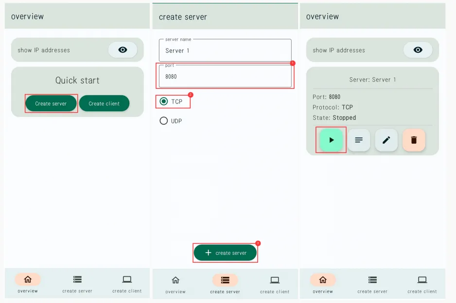
- Modify the serverIP in the code to the IP address (192.168.6.123) of the TCP server created by the mobile phone at last.
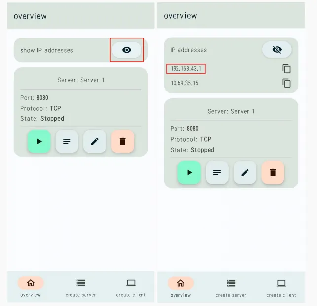
- After flashing the code and a successful connection, the TCP Server will receive the TCP message "Hello world" sent by the ESP32-C6-GEEK, and the LCD will display "Access successful". You can send TCP messages from the mobile TCP Server to the ESP32-C6-GEEK. If sent successfully, the ESP32-C6-GEEK, acting as a TCP Client, will receive the message and display its content on the LCD.
14_WIFI_TCP_Server
This example enables the STA mode of Wi-Fi on the ESP32-C6-GEEK. After connecting to a hotspot opened by a PC, it creates a TCP Server. The PC creates a TCP Client to access the ESP32-C6-GEEK, establishing TCP communication between them. The GEEK displays the received content on the LCD. It is suitable for learning the interaction between the ESP32-C6-GEEK, Wi-Fi, and LCD. It acts as a Wi-Fi server, receives client data and displays it on the LCD, testing stability and reliability.
Code Modification
- Use a PC to open a hotspot, set the network band to "Any available frequency". Ensure the
ssidandpasswordin the program match the Wi-Fi name and password you want to connect to.
Code
14_WIFI_TCP_Server.ino
Code Analysis
Use the
sprintffunction to convert the passed IP address integer into a string in dotted-decimal format and store it in the character array pointed to by theresultpointer.void intToIpAddress(uint32_t ip, char *result) {sprintf(result, "%d.%d.%d.%d", ip & 255,(ip >> 8) & 255,(ip >> 16) & 255,(ip >> 24) & 255);}
Operation Result
- After successful flashing, the LCD displays:
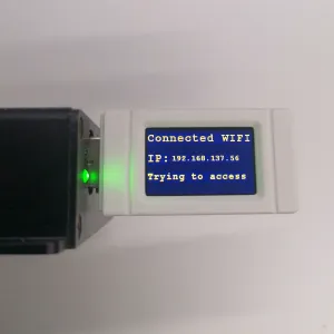
- After Wi-Fi connection, the LCD will display the TCP Server IP. Open a TCP Client in a serial debug assistant to connect and communicate with the ESP32-C6-GEEK (TCP Server).
- ①. Modify the port name to "TCPClient", set the remote address to the IP displayed on the LCD screen, port 8080, and click Connect.
- ②. Check AddCrLf.
- ③. Enter the message.
- ①. Click Send.
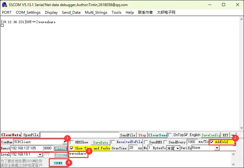
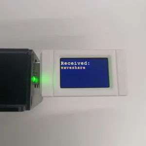
- After the message is sent successfully, the LCD screen displays:
15_WIFI_Web_Server
This example enables the AP mode of Wi-Fi on the ESP32-C6-GEEK. After a PC connects to its Wi-Fi, open a serial debug assistant. Send messages to the GEEK via the HTTP webpage created by the ESP32-C6-GEEK, and observe the received content on the serial debug assistant and LCD. It is suitable for learning the interaction between the ESP32-C6-GEEK, Wi-Fi, and LCD. It acts as a Wi-Fi Access Point server, handles client requests, and tests stability and reliability.
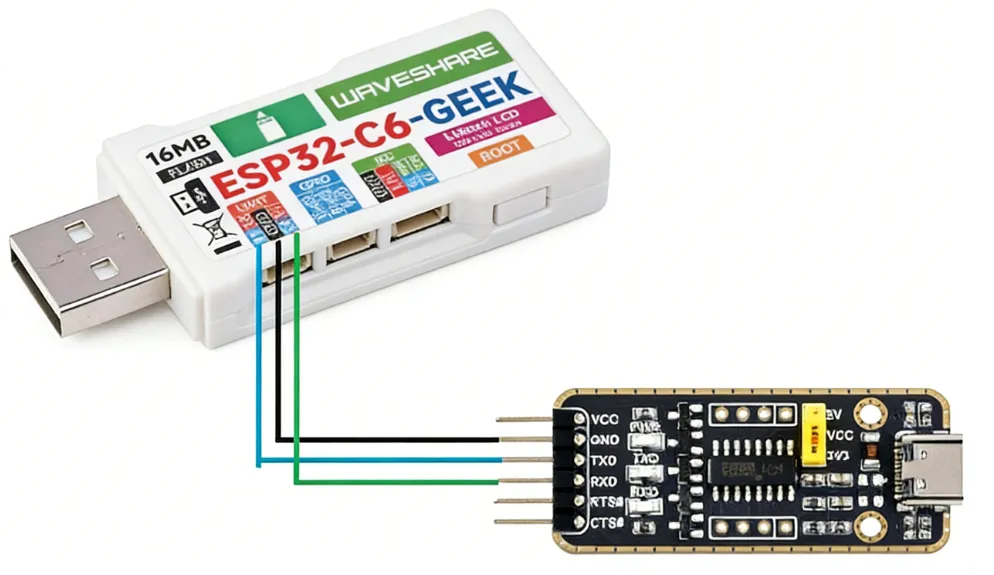
Hardware Connection
- Connect the UART interface of the ESP32-C6-GEEK to a PC using a USB to UART tool, and open a serial debug assistant.
Code
15_WIFI_Web_Server.ino
Code Analysis
Initialize related configurations and the LCD display.
Call
WIFI_AP_Init()to initialize the Wi-Fi Access Point.void setup(){Config_Init();LCD_Init();Serial.begin(115200);LCD_SetBacklight(100);Paint_NewImage(LCD_WIDTH, LCD_HEIGHT, 90, WHITE);Paint_SetRotate(90);LCD_Clear(0x000f);WIFI_AP_Init();}
Operation Result
- After successful flashing, use a PC to connect to the AP of the ESP32-C6-GEEK.
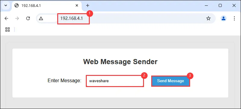
- The LCD will display the IP address of the HTTP server. Use a browser to log in to the IP: 192.168.4.1.
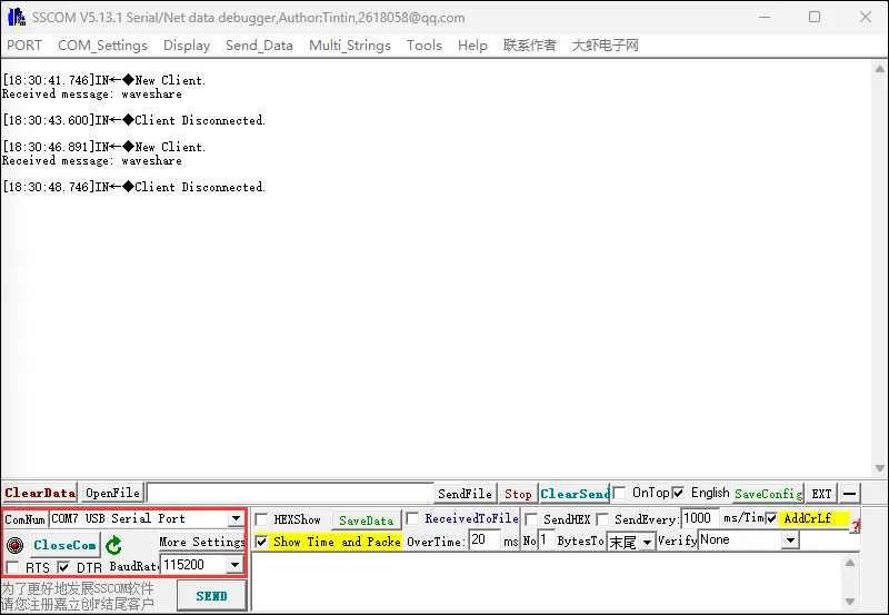
- Connect the UART interface of the ESP32-C6-GEEK to a PC using a USB to UART tool, and open a serial debug assistant.
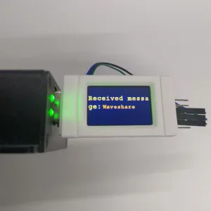
- You can enter text content on the HTTP Web page and send an HTTP request to the ESP32-C6-GEEK. The received content will be displayed on both the serial debug assistant and the LCD.
16_MQTT_sub_pub
This example enables the STA mode of Wi-Fi on the ESP32-C6-GEEK. After connecting to Wi-Fi, it uses the Waveshare Cloud Platform for MQTT communication, subscribing to and publishing topics to achieve long-distance information transmission. It is suitable for learning the interaction between the ESP32-C6-GEEK, Wi-Fi, MQTT, and LCD. It connects to Wi-Fi and an MQTT server, sends/receives JSON data and displays it on the LCD, testing stability and reliability.
Code
16_MQTT_sub_pub.ino
Code Analysis
Convert the received byte array into a string
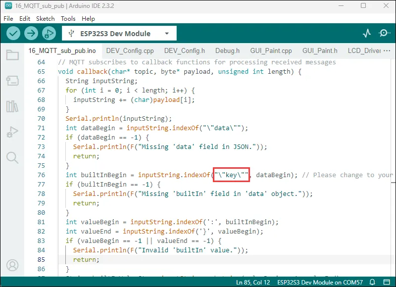
inputString.Find specific JSON fields within the string, such as
"data"and"key"(these can be modified to specific data identifiers according to actual needs).Extract the value of the
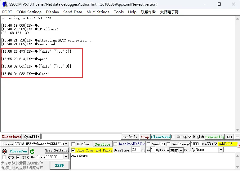
"builtIn"field and perform different operations based on that value. If the value is 0, display "close!" on the LCD; otherwise, display "open!". Also output the corresponding information via the serial port.void callback(char* topic, byte* payload, unsigned int length) {String inputString;for (int i = 0; i < length; i++) {inputString += (char)payload[i];}Serial.println(inputString);int dataBegin = inputString.indexOf("\"data\"");if (dataBegin == -1) {Serial.println(F("Missing 'data' field in JSON."));return;}int builtInBegin = inputString.indexOf("\"key\"", dataBegin); // Please change to your data identifierif (builtInBegin == -1) {Serial.println(F("Missing 'builtIn' field in 'data' object."));return;}int valueBegin = inputString.indexOf(':', builtInBegin);int valueEnd = inputString.indexOf('}', valueBegin);if (valueBegin == -1 || valueEnd == -1) {Serial.println(F("Invalid 'builtIn' value."));return;}String builtInValueStr = inputString.substring(valueBegin + 1, valueEnd);int builtInValue = builtInValueStr.toInt();if (builtInValue == 0) {LCD_Clear(BLACK);Paint_DrawString_EN(75, 55, "close!", &Font24, BLACK, GREEN);Serial.println("close!");}else{LCD_Clear(BLACK);Paint_DrawString_EN(75, 55, "open!", &Font24, BLACK, GREEN);Serial.println("open!");}}Display "Wifi Connecting..." on the LCD.
Output the name of the Wi-Fi network being connected to via the serial port.
After a successful connection, clear the LCD screen and display "Wifi Connected", while also outputting the local IP address via the serial port.
void setup_wifi() {Paint_DrawString_EN(20, 50, "Wifi Connecting...", &Font20, BLACK, GREEN);Serial.println();Serial.print("Connecting to ");Serial.println(ssid);WiFi.mode(WIFI_STA);WiFi.begin(ssid, password);while (WiFi.status() != WL_CONNECTED) {delay(500);Serial.print(".");}LCD_Clear(BLACK);Paint_DrawString_EN(20, 50, "Wifi Connected", &Font20, BLACK, GREEN);Serial.println("IP address: ");Serial.println(WiFi.localIP());}
Code Modification
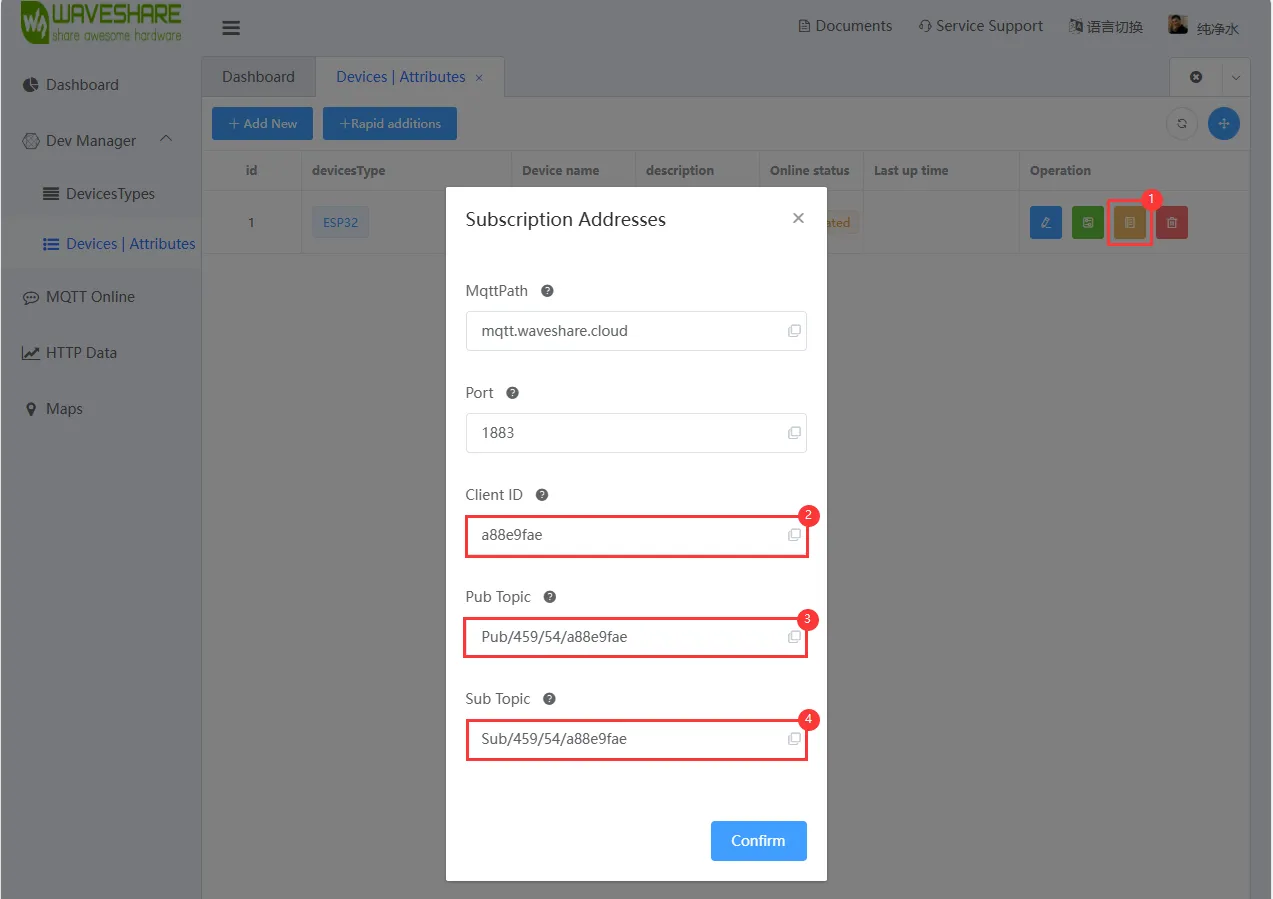
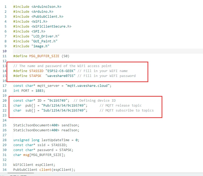
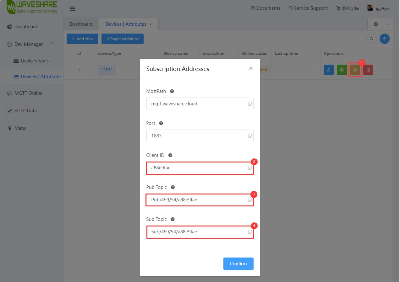
The hotspot name and password you open must match those in the code. After registering an account and creating a device on the Waveshare Cloud Platform, you can view the device's Client ID, Pub Topic, Sub Topic from the "View Address" of the newly created device on the platform. Write these into the example program for assignment, so the ESP32-C6-GEEK can connect to your own cloud platform device.
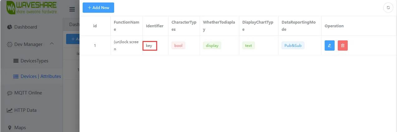
In the callback function, you can modify the recognized identifier to the device property identifier you created on the cloud platform.
Operation Result
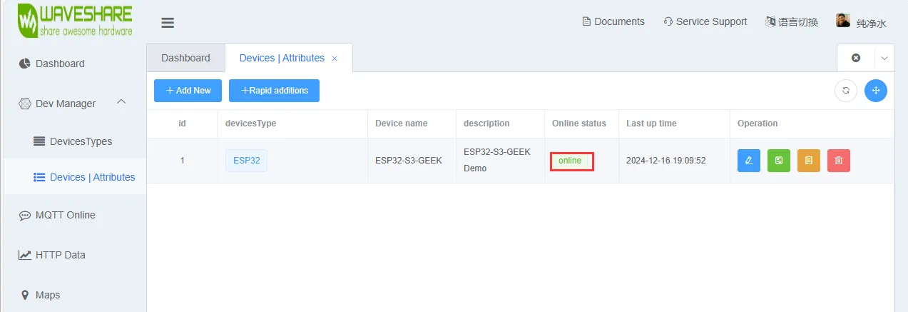
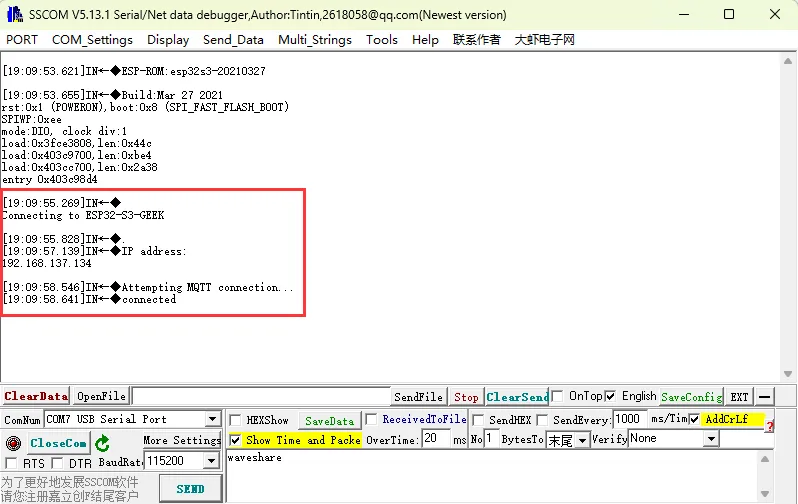
- Flash the code. After connecting to Wi-Fi, check if the device enters the online state on the Waveshare Cloud Platform. If not, try refreshing the webpage or using a USB to UART adapter to connect to a PC and view the Wi-Fi and MQTT connection status via a serial debug assistant. The connection status of Wi-Fi and MQTT will also be displayed on the LCD screen.
- After the ESP32-C6-GEEK successfully connects to the Waveshare Cloud, you can send MQTT messages via the Dashboard.
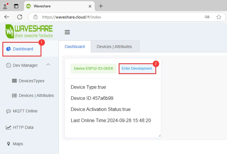
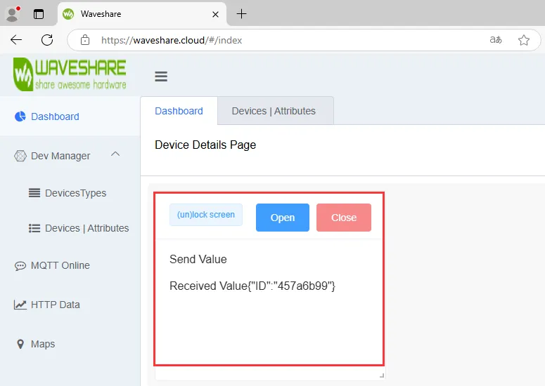
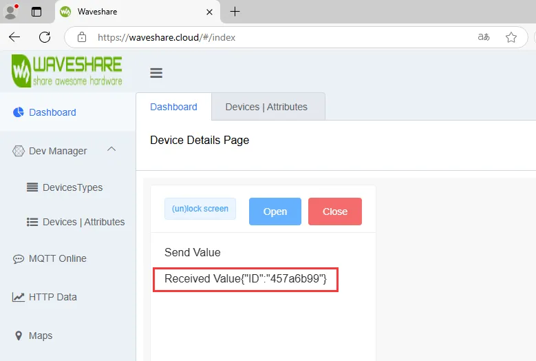
- We can see different feedback on the LCD and serial debug assistant for changes in the device property value (e.g., "key"). Also, in the device's received values on the Waveshare Cloud, we can see the data sent by the ESP32-C6-GEEK to the cloud device (the received value is your own Client ID; you can later send back the return value of "key" or status to the Waveshare Cloud). This achieves MQTT data uplink and downlink, topic subscription and publication.
17_MQTT_BLE_Keyboard
This example enables the STA mode of Wi-Fi and Bluetooth on the ESP32-C6-GEEK. After connecting to Wi-Fi and Bluetooth, it uses the Waveshare Cloud Platform to achieve remote Bluetooth screen locking and password input for unlocking, with more key combinations awaiting your development. It is suitable for integrating BLE keyboard, Wi-Fi, and MQTT on the ESP32-C6-GEEK, controlling LCD display, and testing stability and reliability.
Code
17_MQTT_BLE_Keyboard.ino
Code Analysis
Acts as the callback function for MQTT subscription, used to process received messages.
Prints the topic of the received message, then converts the received byte array into a string.
Finds the specific JSON field
"key"within the string. If your identifier is not"key", you need to modify the code.Extracts the value of the
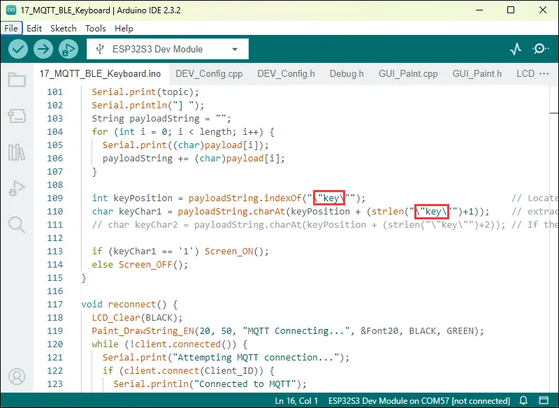
"key"field, and calls theScreen_ONorScreen_OFFfunction depending on whether the value is"1"or something else.void callback(char* topic, byte* payload, unsigned int length) {Serial.print("Message arrived [");Serial.print(topic);Serial.println("] ");String payloadString = "";for (int i = 0; i < length; i++) {Serial.print((char)payload[i]);payloadString += (char)payload[i];}int keyPosition = payloadString.indexOf("\"key\""); // Locate to "key", If your identifier is not "key", change it to your own!char keyChar1 = payloadString.charAt(keyPosition + (strlen("\"key\"")+1)); // extract the first digit of the "key" value// char keyChar2 = payloadString.charAt(keyPosition + (strlen("\"key\"")+2)); // If the extracted value is greater than one digit, add another digitif (keyChar1 == '1') Screen_ON();else Screen_OFF();}Outputs the name of the Wi-Fi network being connected to via the serial port.
Sets the Wi-Fi mode to STA (client mode) and attempts to connect using the specified SSID and password.
During the connection process, continuously outputs connection status information via the serial port in a loop until the connection is successful.
After a successful connection, clear the LCD screen and display "Wifi Connected", while also outputting the local IP address via the serial port.
void setupWiFi() {Paint_DrawString_EN(20, 50, "Wifi Connecting...", &Font20, BLACK, GREEN);Serial.print("Connecting to WiFi: ");WiFi.setSleep(true);WiFi.begin(SSID, PASSWORD);while (WiFi.status() != WL_CONNECTED) {delay(500);Serial.print(".");}LCD_Clear(BLACK);docsPaint_DrawString_EN(20, 50, "Wifi Connected", &Font20, BLACK, GREEN);Serial.println("\nWiFi connected");Serial.println("IP address: " + WiFi.localIP().toString());}
Code Modification
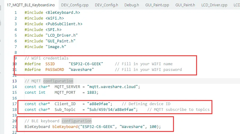
- The hotspot name and password you open must match those in the code (2.4GHz or Any available frequency). After registering an account and creating a device on the Waveshare Cloud Platform, you can view the device's
Client ID, Sub Topicfrom the "View Address" of the newly created device on the platform. Write these into the example program for assignment, so the ESP32-C6-GEEK can connect to your own cloud platform device. - The Bluetooth name and password you connect to must match those in the code.
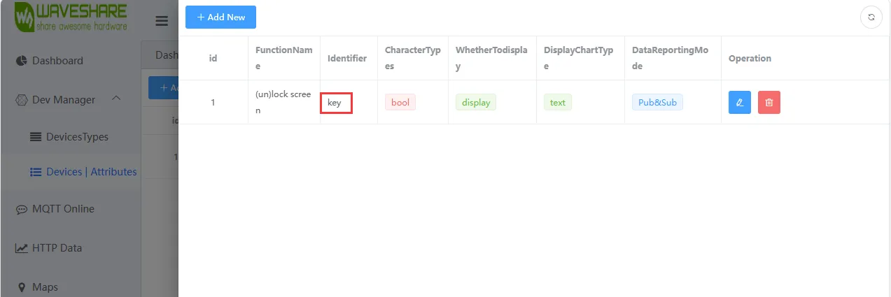
- In the callback function, you can modify the recognized identifier to the device property identifier you created on the cloud platform.
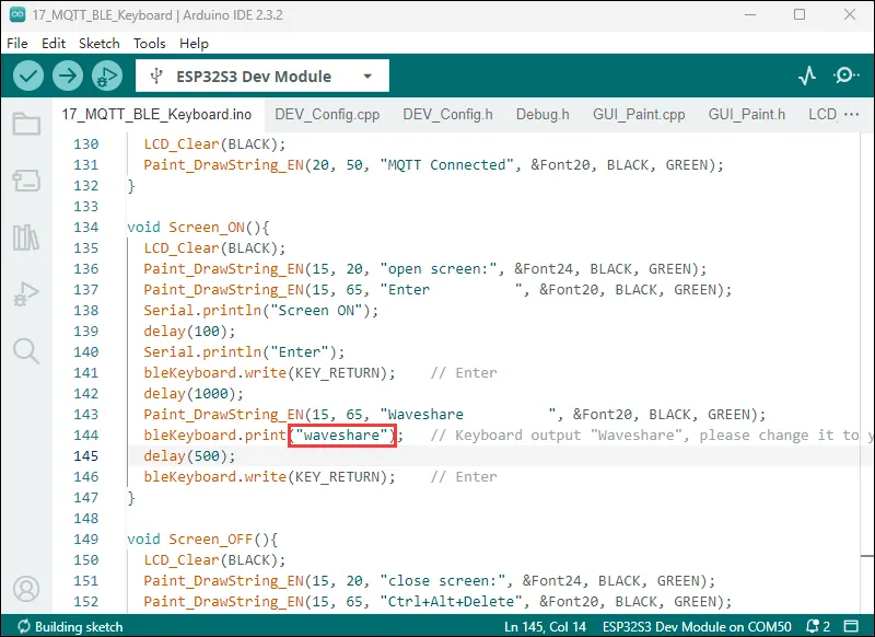
- Modify to the text or password you want to input.
Operation Result
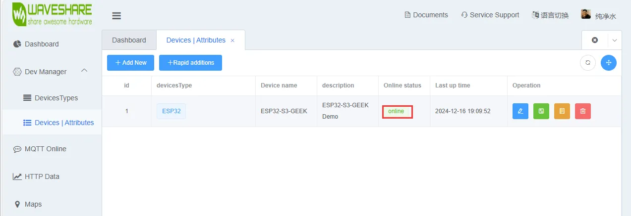
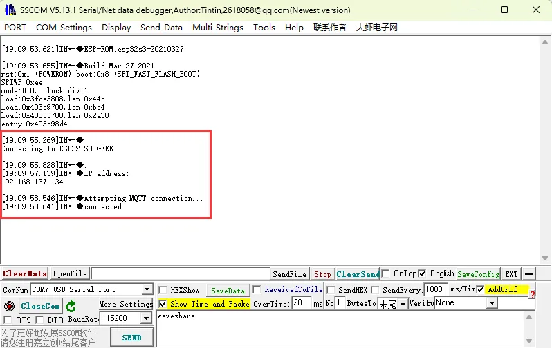
- Flash the code. After connecting to Wi-Fi, turn on the PC's Bluetooth function to pair and connect the device. Check if the device enters the online state on the Waveshare Cloud Platform. If not, try refreshing the webpage or using a USB to UART adapter to connect to a PC and view the Wi-Fi and MQTT connection status via a serial debug assistant. The connection status of Wi-Fi and MQTT will also be displayed on the LCD screen.
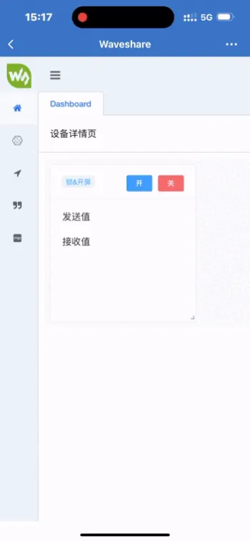
- After the ESP32-C6-GEEK successfully connects to the Waveshare Cloud, you can log in to the Waveshare Cloud Dashboard via a mobile phone for remote control.
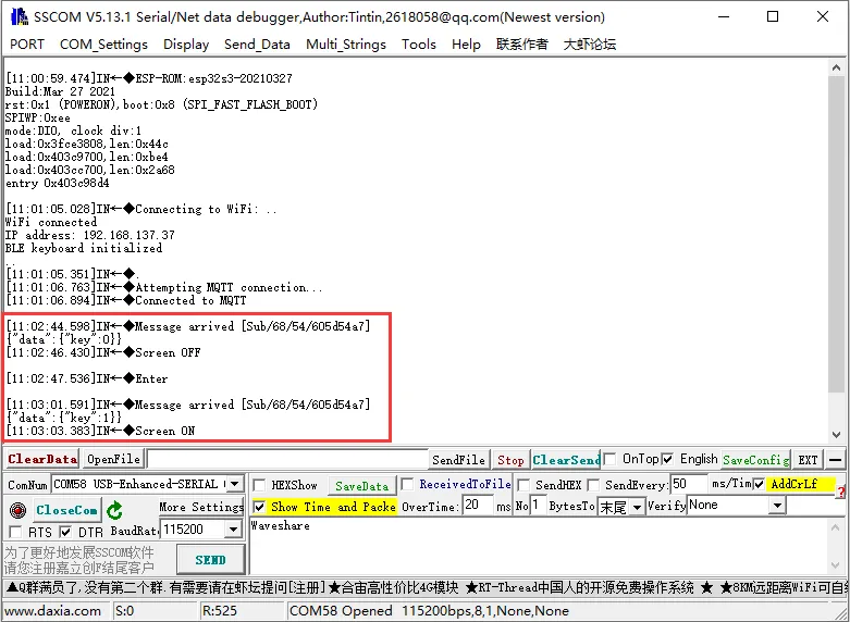
- We can see different feedback on the LCD and serial debug assistant for changes in the device property value (e.g., "key"). Later, you can also modify the keys in the callback function to combinations like Ctrl+C, Ctrl+V, etc., to DIY your own remote-control Bluetooth keyboard.
- You can also test which keys are pressed by the Bluetooth control of the ESP32-C6-GEEK using the Keyboard Tester website.
- Open the keyboard tester interface on your PC, control it via your mobile phone, and the keyboard tester interface will display which keys are being pressed.
Working with ESP-IDF
This chapter includes the following two sections, please read as needed:
Setting up the Development Environment
For the ESP32-C6-GEEK development board, it is recommended to use ESP-IDF V5.5.0 or higher.
The following guide uses Windows as an example, demonstrating development using VS Code + the ESP-IDF extension. macOS and Linux users should refer to the official documentation.
The screenshots in this section use ESP-IDF V5.5.2 as an example. When installing, please select the ESP-IDF version that matches your board's example.
Install the ESP-IDF Development Environment
Download the installation manager from the ESP-IDF Installation Manager page. This is Espressif's latest cross-platform installer. The following steps demonstrate how to use its offline installation feature.
Click the Offline Installer tab on the page, then select Windows as the operating system and the ESP-IDF version you need (the version shown in the screenshot is for reference only — choose the version that fits your actual needs).
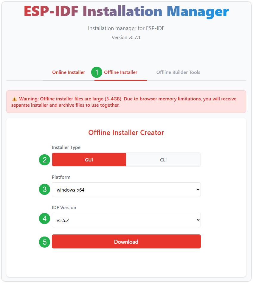
After confirming your selection, click the download button. The browser will automatically download two files: the ESP-IDF Offline Package (.zst) and the ESP-IDF Installer (.exe).
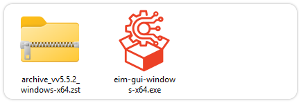
Please wait for both files to finish downloading.
Once the download is complete, double-click to run the ESP-IDF Installer (eim-gui-windows-x64.exe).
The installer will automatically detect if the offline package exists in the same directory. Click Install from archive.
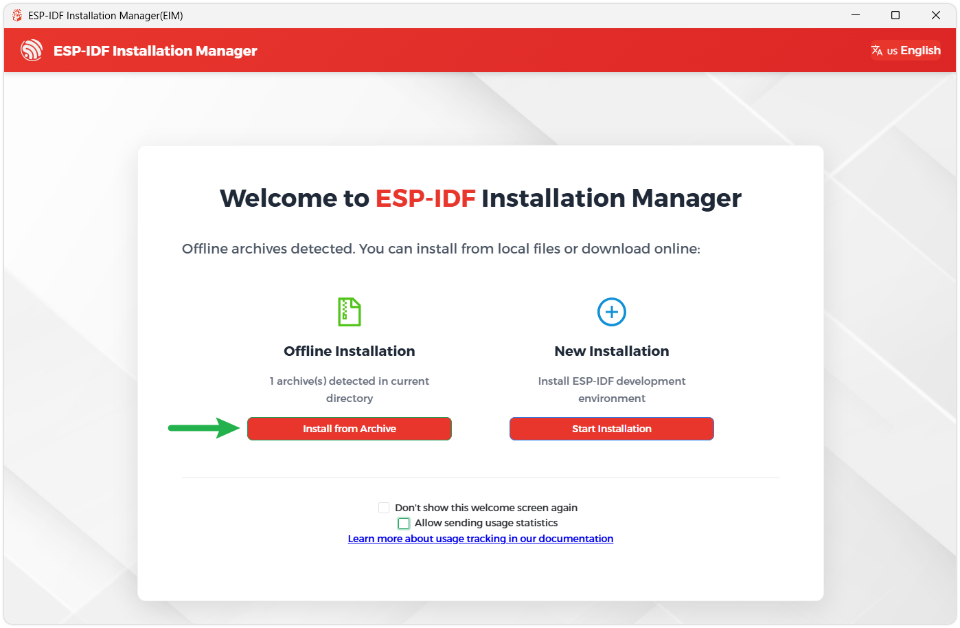
Next, select the installation path. We recommend using the default path. If you need to customize it, ensure the path does not contain Chinese characters or spaces. Click Start installation to proceed.
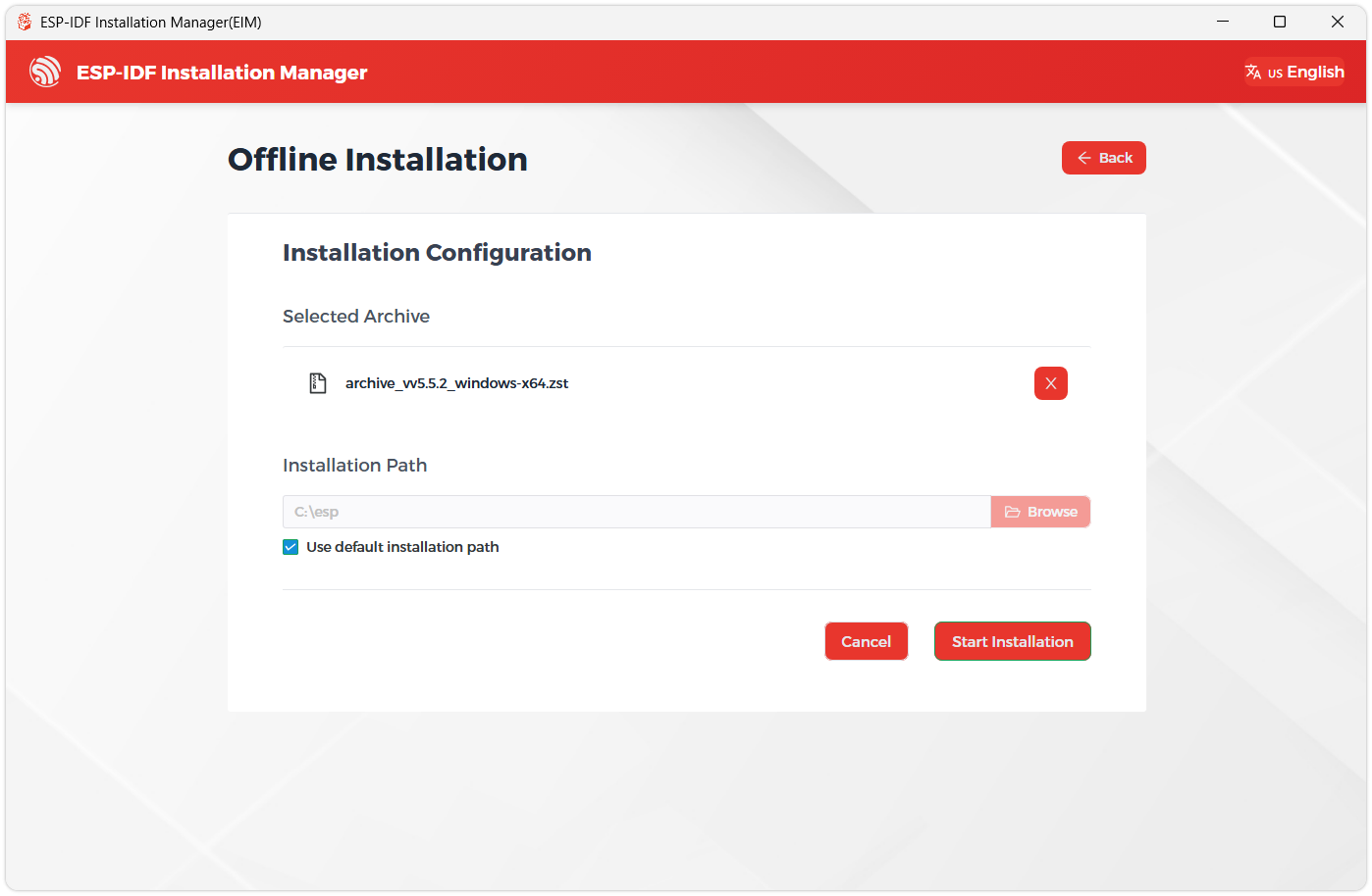
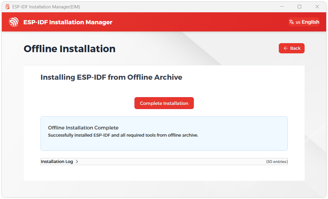
When you see the following screen, the ESP-IDF installation is successful.
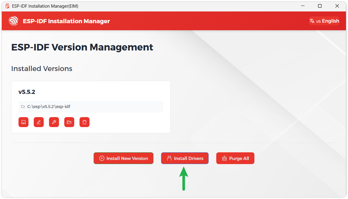
We recommend installing the drivers as well. Click Finish installation, then select Install driver.
Install Visual Studio Code and the ESP-IDF Extension
Download and install Visual Studio Code.
During installation, it is recommended to check Add "Open with Code" action to Windows Explorer file context menu to facilitate opening project folders quickly.
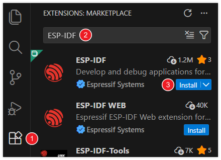
In VS Code, click the Extensions icon
 in the Activity Bar on the side (or use the shortcut Ctrl + Shift + X) to open the Extensions view.
Enter ESP-IDF in the search box, locate the ESP-IDF extension, and click Install.
For ESP-IDF extension versions ≥ 2.0, the extension will automatically detect and recognize the ESP-IDF environment installed in the previous steps, requiring no manual configuration.
Example
The ESP-IDF examples are located in the ESP-IDF directory of the example package.
01_SD_Card
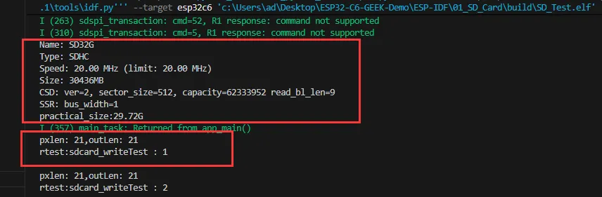
This demo demonstrates how to use ESP32-C6-GEEK to test the read and write functions of the TF card
Additional Preparation
- Insert the TF card into the card slot (TF card needs to be formatted as FAT32)
Code Analysis
Initialize the TF card using SDSPI mode:
SD_card_Init();Test TF card read/write functionality:
example_sdcard_task();
02_WIFI_AP
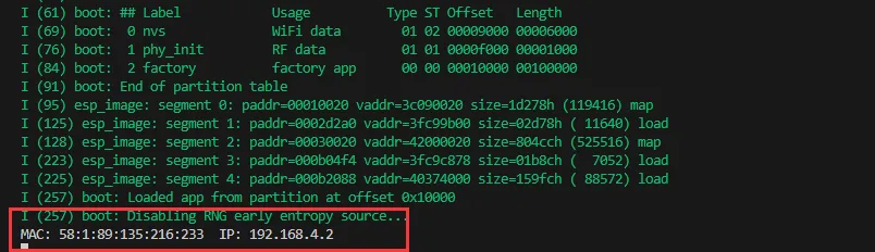
This demo can set the development board as a hotspot, allowing phones or other devices in STA mode to connect to the development board.
Code Analysis
In the file
softap_example_main.c, findSSIDandPASSWORD, and then your phone or other device in STA mode can use theSSIDandPASSWORDto connect to the development board.#define EXAMPLE_ESP_WIFI_SSID "waveshare_esp32"#define EXAMPLE_ESP_WIFI_PASSWORD "wav123456"
03_WIFI_STA
This example can configure the development board as a STA device to connect to a router, thereby enabling access to the system network.
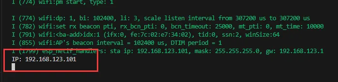
Code Analysis In the file esp_wifi_bsp.c, find ssid and password, then modify them to the SSID and Password of an available router in your current environment.
  wifi_config_t wifi_config = {
      .sta = {
        .ssid = "PDCN",
        .password = "1234567890",
      },
  };
04_Button
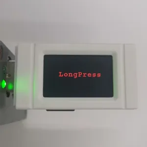
This example demonstrates how to use the Boot button as a multi-functional button, capable of performing different actions such as single-click, double-click, or long-press.
Code Analysis
Initialize the Boot button and bind the button event function:
void button_init(void){button_config_t btn_cfg = {0};button_gpio_config_t gpio_cfg = {.gpio_num = BOOT_BUTTON_NUM,.active_level = 0,.enable_power_save = true,};esp_err_t ret = iot_button_new_gpio_device(&btn_cfg, &gpio_cfg, &boot_btn);assert(ret == ESP_OK);ret |= iot_button_register_cb(boot_btn, BUTTON_SINGLE_CLICK, NULL, button_event_cb, NULL);ret |= iot_button_register_cb(boot_btn, BUTTON_DOUBLE_CLICK, NULL, button_event_cb, NULL);ret |= iot_button_register_cb(boot_btn, BUTTON_LONG_PRESS_START, NULL, button_event_cb, NULL);}
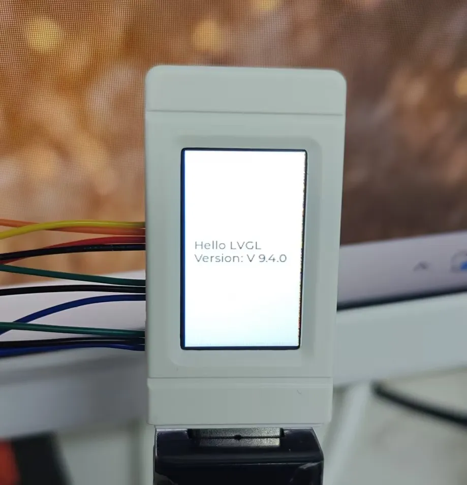
05_lvgl_example
Implement some multi-functional GUI interfaces on the screen by porting LVGL.
Firmware Flashing and Erasing
This product provides test firmware that can be flashed directly to verify whether the onboard devices are functioning properly.
- Firmware download: ESP32-C6-GEEK Example. The bin file is located in the
Firmwaredirectory of the example package. - Flash address:
0x00
- Firmware Flashing
- Firmware Erasing
The following uses flashing the ESP32-S3-Touch-LCD-2.8 factory firmware as an example. The same steps apply when flashing other firmware.
Download and extract Espressif's official Flash Download Tool (Download)
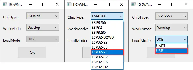
Run flash_download_tool_3.9.7.exe and select the development board's MCU and download interface, such as ESP32-S3 and USB (most devices use USB; refer to the product's hardware design for the correct interface).
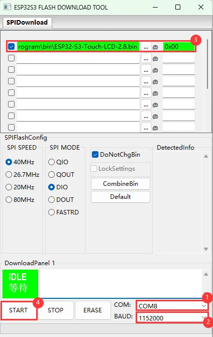
Parameter settings
- Select the COM port for the development board
- Set BAUD to the maximum value, 1152000
- Click the "..." button in the row, select the bin file provided by Waveshare, manually enter the flash address given at the top of this page in the field to its right, and select the leftmost checkbox in the row
- Click START to begin flashing
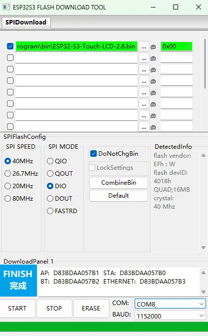
Wait for flashing to complete (this may take some time; please be patient)
Press the reset button and verify the result
Resources
1. Hardware Resources
Development Board Design Files
2. Technical Manuals
ESP32-C6 Chip Official Manuals
Datasheets
3. Example
4. Software Tools
- Debugging Tools:
- Firmware Flashing Tool:
Support
Monday-Friday (9:30-6:30) Saturday (9:30-5:30)
Email: services01@spotpear.com
[Tutorial Navigation]
- Features
- Onboard Resources
- LCD Screen Specifications
- Dimensions
- Working with Arduino
- Arduino Getting Started Tutorial
- Setting Up Development Environment
- Example
- Working with ESP-IDF
- Firmware Flashing and Erasing
- Resources
- Support