


- sales/support
Google Chat:---
- sales
+86-0755-88291180
- sales01
sales@spotpear.com
- sales02
dragon_manager@163.com
- support
tech-support@spotpear.com
- CEO-Complaints
zhoujie@spotpear.com
- Only Tech-Support
WhatsApp:13246739196
- Purchase/Shipping/Refund
WhatsApp:13424403025
RP2350-Touch-LCD-2.8C User Guide
Overview
Introduction
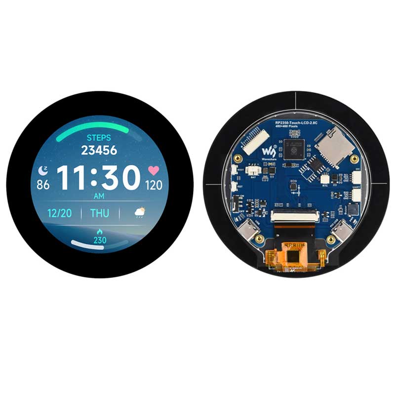
RP2350-Touch-LCD-2.8 is a low-cost, high-performance MCU board designed by Waveshare. It features a 2.8inch LCD display, Li-ion battery recharging chip, 6-axis sensor (3-axis accelerometer and 3-axis gyroscope), RTC and other peripherals, making it easy to develop and embed into the product. It can run GUI interface programs such as LVGL smoothly.
Features
- RP2350B microcontroller chip officially designed by Raspberry Pi
- Unique dual-core and dual-architecture design, equipped with dual-core ARM Cortex-M33 processor and dual-core Hazard3 RISC-V processor, flexible clock running up to 150 MHz, supporting flexible switching between the two architectures
- Built-in 520KB of SRAM and 16MB of on-chip Flash
- Onboard 2.8inch LCD screen with 480×480 resolution
- Supports touch control via I2C interface, with interrupt support
- Supports USB1.1 host and slave device
- Low-power sleep and dormant modes
- Drag-and-drop programming using mass storage over USB
- Onboard QMI8658 6-axis sensor, RTC clock sensor, TF card slot and battery charging management module, etc.
- Accurate clock and timer on-chip
- Temperature sensor
- On-chip accelerated floating-point library
- 12 × Programmable I/O (PIO) state machines for custom peripheral support
Specifications
| LCD parameters | |||
| Display Panel | IPS | Display Size | 2.8inch |
| Display Resolution | 480 × 480 | Contrast | 1200:1 |
| Communication interface | RGB | Display IC | ST7701 |
| Touch Port | I2C | Touch IC | GT911 |
| IMU parameters | |||
| Sensor Name | QMI8658 | ||
| Accelerometer Characteristics | Resolution: 16 bits Measuring Range (optional): ±2, ±4, ±8, ±16g | ||
| Gyroscope Characteristics | Resolution: 16 bits Measuring Range (optional): ±16, ±32, ±64, ±128, ±256, ±512, ±1024, ±2048°/sec | ||
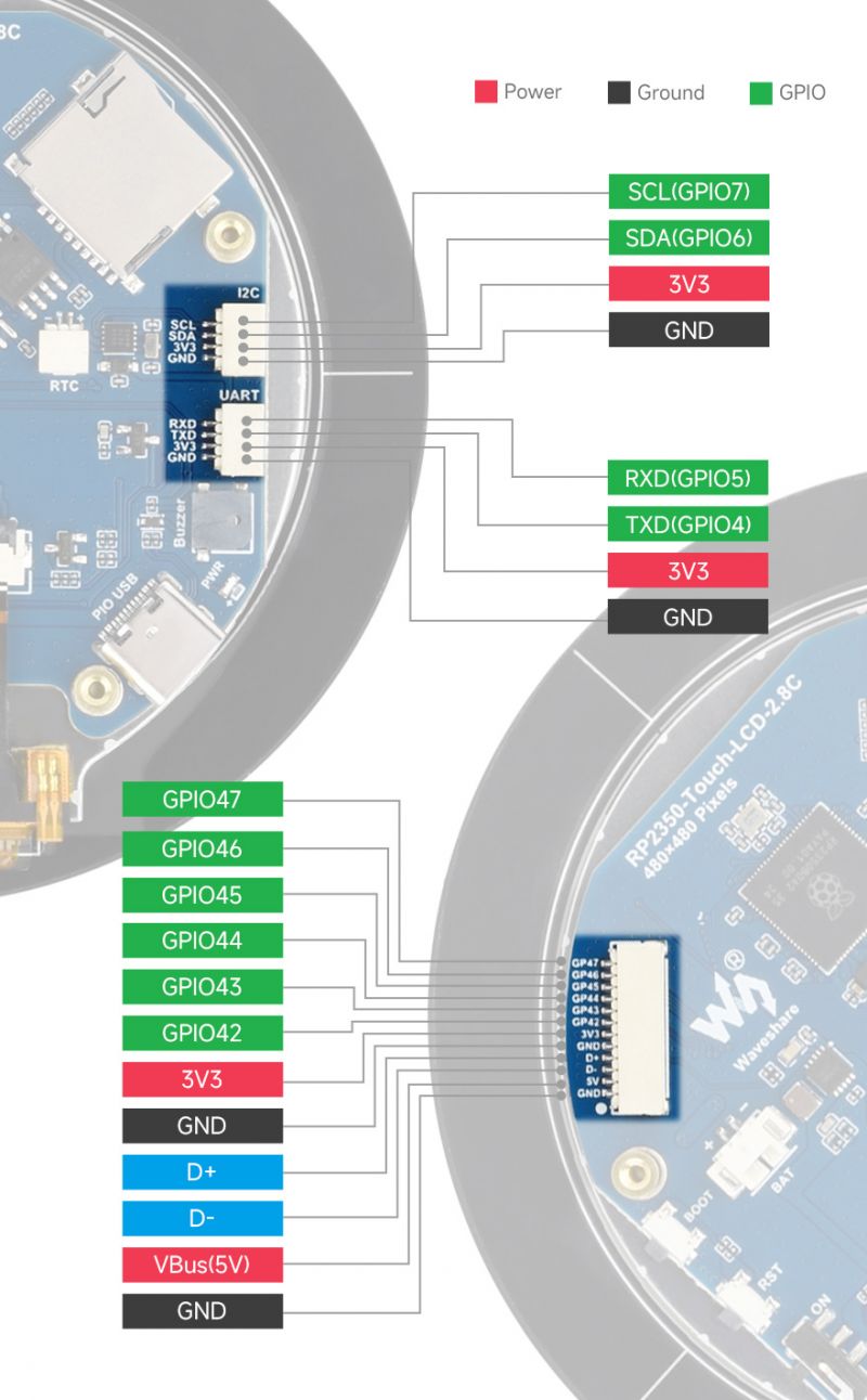
Pinout Definition
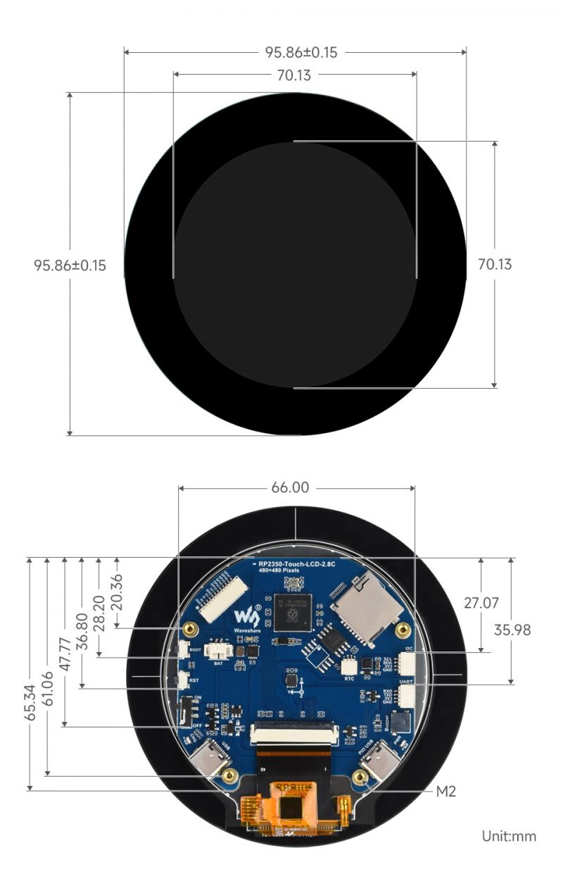
Dimensions
Pico Getting Started
Firmware Download
- MicroPython Firmware Download

- C_Blink Firmware Download

Basic Introduction
MicroPython Series
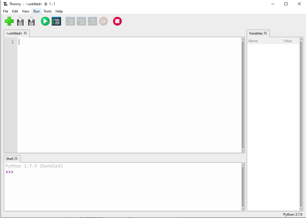
Install Thonny IDE
In order to facilitate the development of Pico/Pico2 boards using MicroPython on a computer, it is recommended to download the Thonny IDE
- Download Thonny IDE and follow the steps to install, the installation packages are all Windows versions, please refer to Thonny's official website for other versions
- After installation, the language and motherboard environment need to be configured for the first use. Since we are using Pico/Pico2, pay attention to selecting the Raspberry Pi option for the motherboard environment
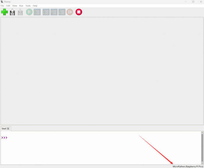
- Configure MicroPython environment and choose Pico/Pico2 port
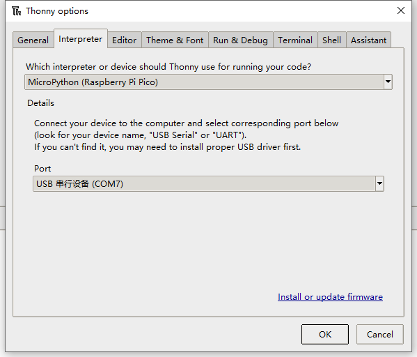
- Connect Pico/Pico2 to your computer first, and in the lower right corner of Thonny left-click on the configuration environment option --> select Configture interpreter
- In the pop-up window, select MicroPython (Raspberry Pi Pico), and choose the corresponding port
Flash Firmware
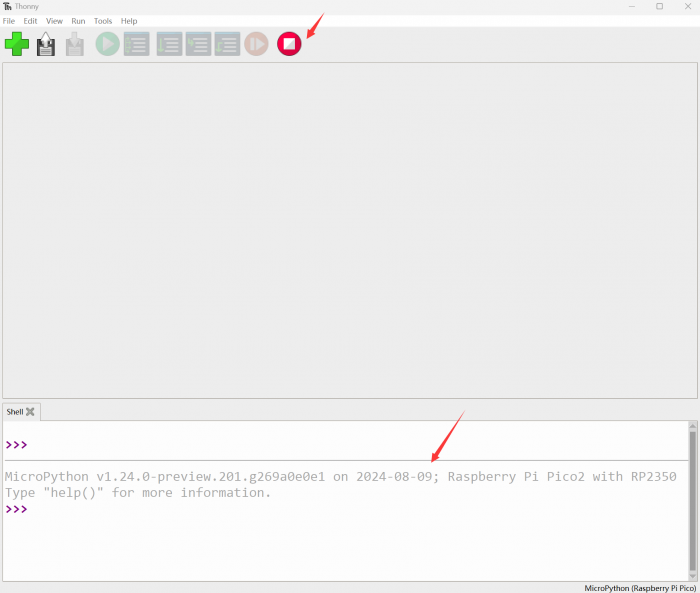
- Click OK to return to the Thonny main interface, download the corresponding firmware library and burn it to the device, and then click the Stop button to display the current environment in the Shell window
- Note: Flashing the Pico2 firmware provided by Micropython may cause the device to be unrecognized, please use the firmware below or in the package
- How to download the firmware library for Pico/Pico2 in windows: After holding down the BOOT button and connecting to the computer, release the BOOT button, a removable disk will appear on the computer, copy the firmware library into it
- How to download the firmware library for RP2040/RP2350 in windows: After connecting to the computer, press the BOOT key and the RESET key at the same time, release the RESET key first and then release the BOOT key, a removable disk will appear on the computer, copy the firmware library into it (you can also use the Pico/Pico2 method)
MicroPython Series Tutorials
【MicroPython】 machine.Pin class function details
【MicroPython】machine.PWM class function details
【MicroPython】machine.ADC class function details
【MicroPython】machine.UART class function details
【MicroPython】machine.I2C class function details
【MicroPython】machine.SPI class function details
【MicroPython】rp2.StateMachine class function details
C/C++ Series
For C/C++, it is recommended to use Pico VSCode for development. This is a Microsoft Visual Studio Code extension designed to make it easier for you to create, develop, and debug projects for the Raspberry Pi Pico series development boards. No matter if you are a beginner or an experienced professional, this tool can assist you in developing Pico with confidence and ease. Here's how to install and use the extension.
- Official website tutorial: https://www.raspberrypi.com/news/pico-vscode-extension/
- This tutorial is suitable for Raspberry Pi Pico, Pico2 and the RP2040 and RP2350 series development boards developed by Waveshare
- The development environment defaults to Windows11. For other environments, please refer to the official tutorial for installation
Install VSCode
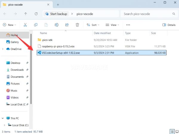
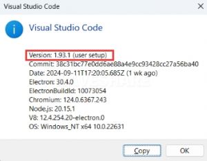
- First, click to download pico-vscode package, unzip and open the package, double-click to install VSCode
Note: If vscode is installed, check if the version is v1.87.0 or later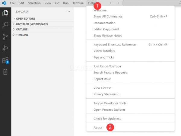
Install Extension
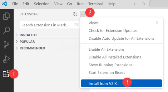
- Click Extensions and select Install from VSIX
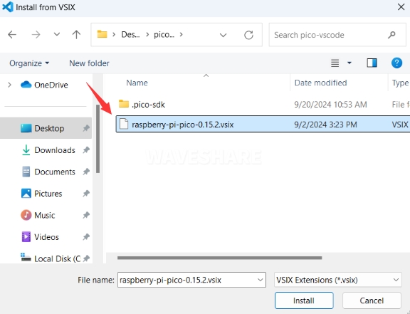
- Select the package with the vsix suffix and click Install
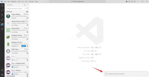
- Then vscode will automatically install raspberry-pi-pico and its dependency extensions, you can click Refresh to check the installation progress
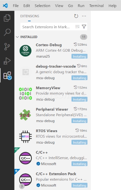
- The text in the right lower corner shows that the installation is complete. Close VSCode
Configure Extension
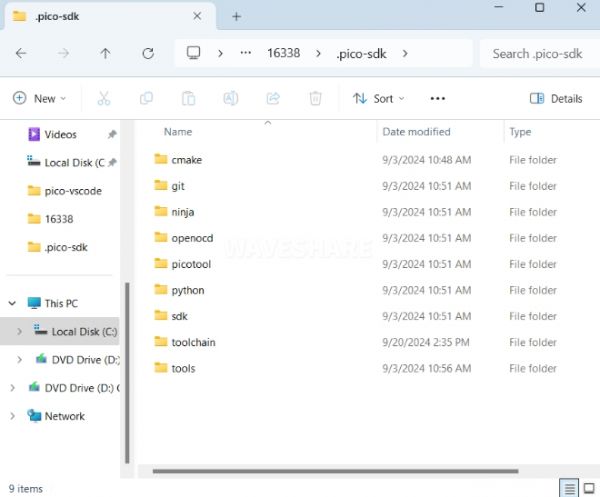
- Open directory C:\Users\username and copy the entire .pico-sdk to that directory
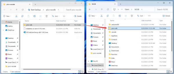
- The copy is completed
- Open vscode and configure the paths for the Raspberry Pi Pico extensions
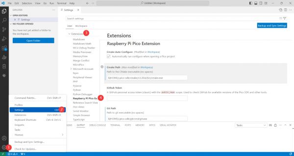
The configuration is as follows:Cmake Path: ${HOME}/.pico-sdk/cmake/v3.28.6/bin/cmake.exe Git Path: ${HOME}/.pico-sdk/git/cmd/git.exe Ninja Path: ${HOME}/.pico-sdk/ninja/v1.12.1/ninja.exe Python3 Path: ${HOME}/.pico-sdk/python/3.12.1/python.exe
New Project
- The configuration is complete, create a new project, enter the project name, select the path, and click Create to create the project
To test the official example, you can click on the Example next to the project name to select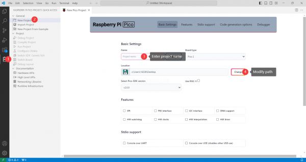
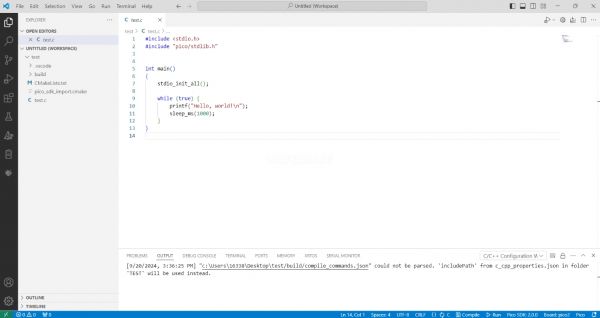
- The project is created successfully
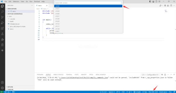
Compile Project
- Select the SDK version
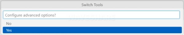
- Select Yes for advanced configuration
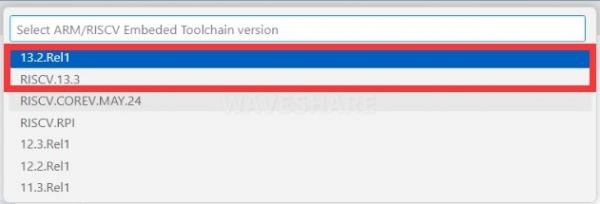
- Choose the cross-compilation chain, 13.2.Rel1 is applicable for ARM cores, RISCV.13.3 is applicable for RISCV cores. You can select either based on your requirements
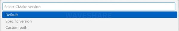
- Select Default for CMake version (the path configured earlier)
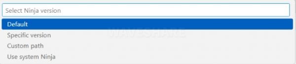
- Select Default for Ninjaversion
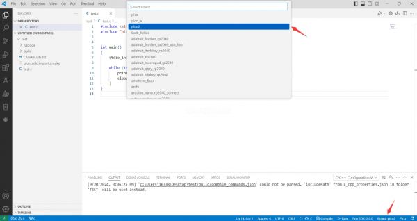
- Select the development board
- Click Complie to compile
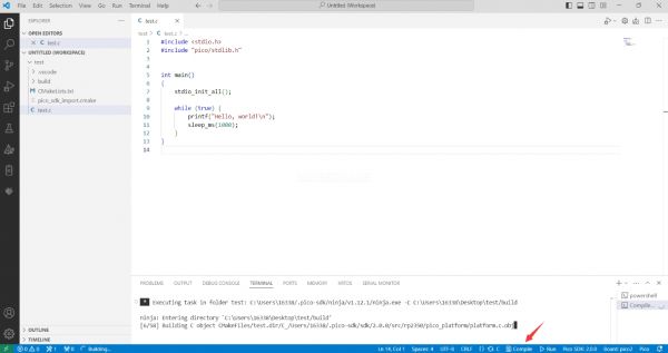
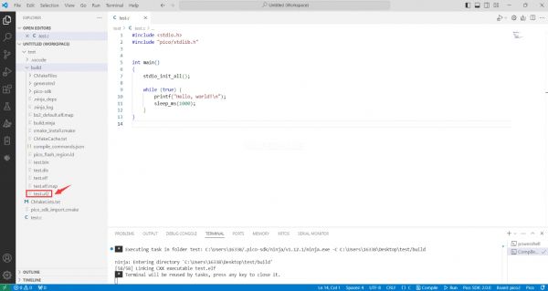
- The uf2 format file is successfully compiled
Flash Firmware
Here are two methods for flashing firmware
- Flash firmware using the pico-vscode plugin
Connect the development board to the computer, click Run to flash the firmware directly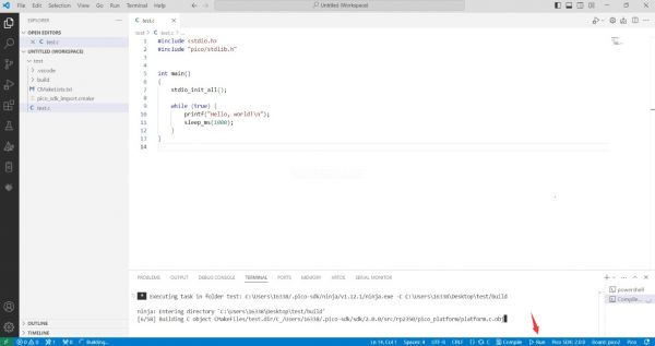
- Flash the firmware manually
1. Press and hold the Boot button
2. Connect the development board to the computer
3. Then the computer will recognize the development board as a USB device.
4. Copy the .uf2 file to the USB drive, and the device will automatically restart, indicating successful program flashing.
Import Project
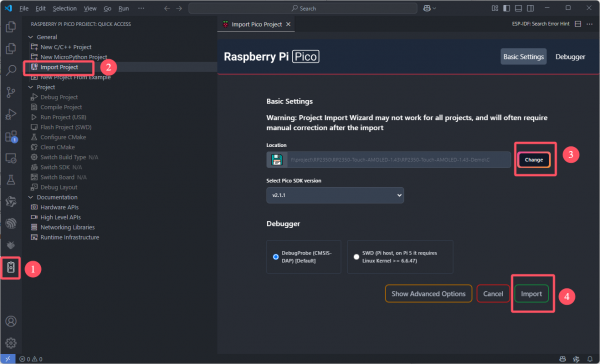
- Select the project directory and import the project
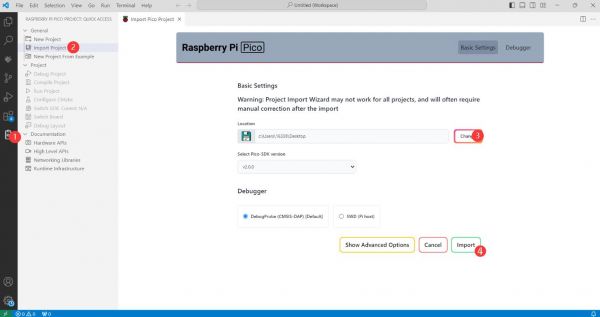
- The Cmake file of the imported project cannot have Chinese (including comments), otherwise the import may fail
- To import your own project, you need to add a line of code to the Cmake file to switch between pico and pico2 normally, otherwise even if pico2 is selected, the compiled firmware will still be suitable for pico
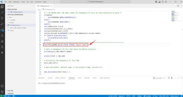
set(PICO_BOARD pico CACHE STRING "Board type")
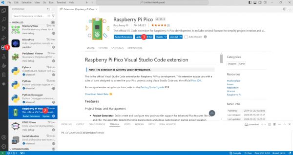
Update Extension
- The extension version in the offline package is 0.15.2, and you can also choose to update to the latest version after the installation is complete
Arduino IDE Series
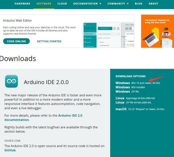
Install Arduino IDE
- First, go to Arduino official website to download the installation package of the Arduino IDE.
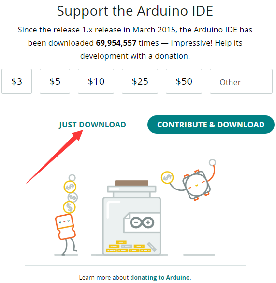
- Here, you can select Just Download.
- Once the download is complete, click Install.
Notice: During the installation process, it will prompt you to install the driver, just click Install
Arduino IDE Interface
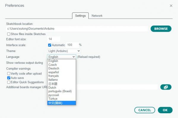
- After the first installation, when you open the Arduino IDE, it will be in English. You can switch to other languages in File --> Preferences, or continue using the English interface.
- In the Language field, select the language you want to switch to, and click OK.
Install Arduino-Pico Core in Arduino IDE
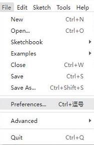
- Open the Arduino IDE, click on the file in the top left corner, and select Preferences

- Add the following link to the attached board manager URL, and then click OK
This link already includes board versions such as RP2040 and RP2350. Please visit arduino-pico for the latest version fileshttps://github.com/earlephilhower/arduino-pico/releases/download/4.5.2/package_rp2040_index.json
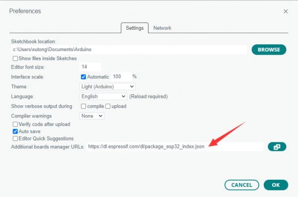
Note: If you already have an ESP32 board URL, you can use a comma to separate the URLs as follows:https://dl.espressif.com/dl/package_esp32_index.json,https://github.com/earlephilhower/arduino-pico/releases/download/4.5.2/package_rp2040_index.json
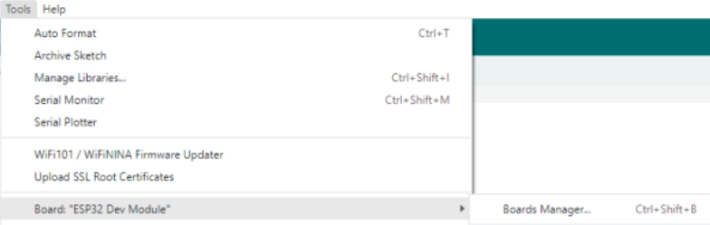
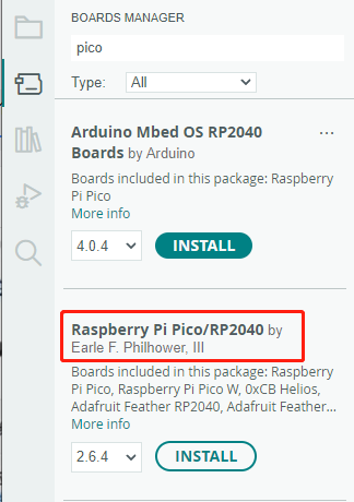
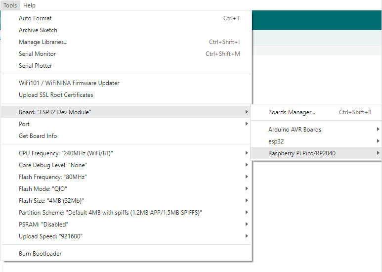
- Click Tools > Board > Board Manager > Search pico, as my computer has already been installed, it shows that it is installed
Upload Demo at the First Time
- Press and hold the BOOTSET button on the Pico board, connect the pico to the USB port of the computer via the Micro USB cable, and release the button after the computer recognizes a removable hard disk (RPI-RP2).
- Download the program and open D1-LED.ino under the arduino\PWM\D1-LED path
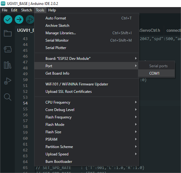
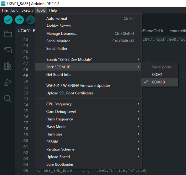
- Click Tools --> Port, remember the existing COM, do not click this COM (the COM displayed is different on different computers, remember the COM on your own computer)
- Connect the driver board to the computer using a USB cable. Then, go to Tools > Port. For the first connection, select uf2 Board. After uploading, when you connect again, an additional COM port will appear
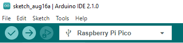
- Click Tools > Development Board > Raspberry Pi Pico > Raspberry Pi Pico or Raspberry Pi Pico 2

- After setting it up, click the right arrow to upload the program
- If issues arise during this period, and if you need to reinstall or update the Arduino IDE version, it is necessary to uninstall the Arduino IDE completely. After uninstalling the software, you need to manually delete all contents within the C:\Users\[name]\AppData\Local\Arduino15 folder (you need to show hidden files to see this folder). Then, proceed with a fresh installation.
Open Source Demos
MircoPython video demo (github)
MicroPython firmware/Blink demos (C)
Raspberry Pi official C/C++ demo (github)
Raspberry Pi official micropython demo (github)
Arduino official C/C++ demo (github)
Demo
Working with C
Directory Structure
├── CMakeLists.txt
├── example_auto_set_url.cmake
├── examples # Demos
│   ├── CMakeLists.txt
│   ├── adc_battery # Demo of serial port printing battery voltage
│   ├── button # Demo of obtaining BOOT button status
│   ├── buzzer # Demo of driving buzzer
│   ├── gui # Demo of using GUI library to display content on LCD
│   ├── hello_world # Demo of printing hello world
│   │   ├── CMakeLists.txt
│   │   ├── serial
│   │   └── usb
│   ├── lcd # Demo of Testing LCD
│   │   ├── CMakeLists.txt
│   │   ├── lcd_flush_rgb
│   │   ├── lcd_image
│   │   └── lcd_touch
│   ├── lvgl # Demos using LVGL
│   │   ├── CMakeLists.txt
│   │   ├── factory # Pre-installed demo
│   │   ├── lv_port # Source files for LVGL hardware integration
│   │   ├── lvgl_example # Demo of running LVGL's own demo
│   │   ├── lvgl_pcf85063 # Demo of using LVGL to display time and date
│   │   └── lvgl_qmi8658 # Demo of using LVGL to display IMU data
│   ├── qmi8658_raw_out # Demo of using serial port to print IMU data
│   ├── rtc_pcf85063 # Demo of using serial port to print time and date
│   └── sd_card_spi # Demo for testing TF Card read and write
├── libraries # Library files
│   ├── CMakeLists.txt
│   ├── Fonts
│   ├── GUI
│   ├── bsp # Hardware-related libraries
│   ├── lvgl # LVGL library
│   └── no-OS-FatFS-SD-SDIO-SPI-RPi-Pico # TF Card related libraries
├── pico_extras_import_optional.cmake
└── pico_sdk_import.cmake
Compile
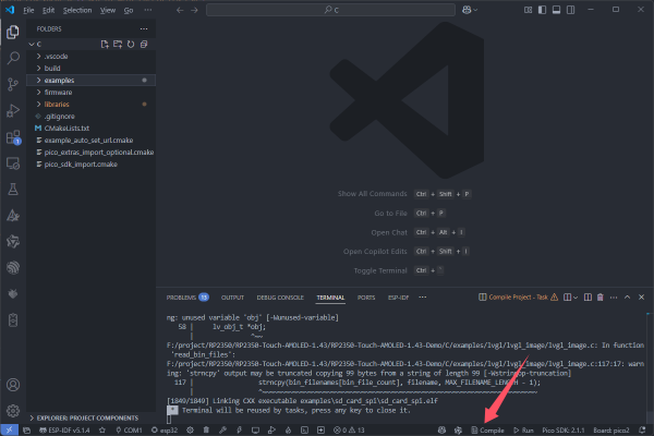
If Using the VSCode Raspberry Pi Pico Plugin
- Import project, and select project directory
- Click Comple to compile
If Using Ubuntu
cd RP2350-Touch-LCD-2.8C-Demo/C
mkdir build
cd build
cmake ..
make -j8
Compiled Firmware
- After compilation, a .uf2 file will be generated in the build/examples directory
Flash Firmware
- Press and hold the BOOT button on the board, connect the board to the USB port of the computer through the Type-C cable, then release the button. The computer will recognize it as a removable drive, and finally copy the compiled .uf2 format file to the removable drive.
New Project
- Let's take the example of creating a new project named lvgl_test.
- Create a new folder lvgl_test in the examples/lvgl directory and create new CMakeLists.txt and main.c files in this folder.
- The content of the CMakeLists.txt file is
add_executable(lvgl_test
    lvgl_test.c
    ../lv_port/lv_port_disp.c
    ../lv_port/lv_port_indev.c
    )

pico_enable_stdio_usb(lvgl_test 1)
pico_enable_stdio_uart(lvgl_test 0)

# pull in common dependencies
target_link_libraries(lvgl_test
    pico_stdlib
    bsp
    lvgl
    lvgl::demos)

target_compile_definitions(lvgl_test PRIVATE
    PICO_EMBED_XIP_SETUP=1
)
# create map/bin/hex/uf2 file etc.
pico_add_extra_outputs(lvgl_test)
- The content of the main.c file is
#include <stdio.h>
#include "pico/stdlib.h"

#include "bsp_i2c.h"
#include "../lv_port/lv_port_disp.h"
#include "../lv_port/lv_port_indev.h"
#include "demos/lv_demos.h"

#include "hardware/pll.h"
#include "hardware/clocks.h"
#include "hardware/structs/pll.h"
#include "hardware/structs/clocks.h"

#define LVGL_TICK_PERIOD_MS 10
void set_cpu_clock(uint32_t freq_Mhz)
{
    set_sys_clock_khz(freq_Mhz * 1000, true);
    clock_configure(
        clk_peri,
        0,
        CLOCKS_CLK_PERI_CTRL_AUXSRC_VALUE_CLKSRC_PLL_SYS,
        freq_Mhz * 1000 * 1000,
        freq_Mhz * 1000 * 1000);
}

static bool repeating_lvgl_timer_cb(struct repeating_timer *t)
{
    lv_tick_inc(LVGL_TICK_PERIOD_MS);
    return true;
}

int main()
{
    static struct repeating_timer lvgl_timer;
    set_cpu_clock(240);
    stdio_init_all();
    bsp_i2c_init();
    lv_init();
    lv_port_disp_init();
    lv_port_indev_init();
    add_repeating_timer_ms(LVGL_TICK_PERIOD_MS, repeating_lvgl_timer_cb, NULL, &lvgl_timer);

    // lv_demo_benchmark();
    lv_demo_music();
    // lv_demo_widgets();
    while (true)
    {
        lv_timer_handler();
        sleep_ms(LVGL_TICK_PERIOD_MS);
    }
}
- Add at the end of CMakeLists.txt in the examples/lvgl directory.
add_subdirectory(${CMAKE_CURRENT_LIST_DIR}/lvgl_test)
- Recompile, build/examples/lvgl will add a new folder lvgl_test, which contains the compiled and generated .uf2 files.
Resources
Supporting Resources
Demo
Schematic Diagram
Datasheets
Official Resources
Raspberry Pi Official Documents
- Get Started with MicroPython on Raspberry Pi Pico
- Raspberry Pi related books download
- Pico2 Schematic diagram
- Pico2 Pinout definition
- Pico2 Getting Started
- Pico2 C SDK User Manual
- Pico2 Python SDK User Manual
- Pico2 Datasheet
- RP2350 Datasheet
- RP2350 Hardware Design Reference Manual
Raspberry Pi Open Source Demos
Development Softwares
FAQ
Question: GPIO is configured as a pull-down input, why does reading IO show a high voltage level when the pin is left unconnected?
You can refer to the RP2350-E9 section in the RP2350 Datasheet
Support
Monday-Friday (9:30-6:30) Saturday (9:30-5:30)
Email: services01@spotpear.com
[Tutorial Navigation]
- Overview
- Introduction
- Features
- Specifications
- Pinout Definition
- Dimensions
- Pico Getting Started
- Firmware Download
- Basic Introduction
- MicroPython Series
- C/C++ Series
- Install VSCode
- Install Extension
- Configure Extension
- New Project
- Compile Project
- Flash Firmware
- Import Project
- Update Extension
- Arduino IDE Series
- Install Arduino IDE
- Arduino IDE Interface
- Install Arduino-Pico Core in Arduino IDE
- Upload Demo at the First Time
- Open Source Demos
- Demo
- Resources
- FAQ
- Support