




- sales/support
Google Chat:---
- sales
+86-0755-88291180
- sales01
sales@spotpear.com
- sales02
dragon_manager@163.com
- support
tech-support@spotpear.com
- CEO-Complaints
zhoujie@spotpear.com
- Only Tech-Support
WhatsApp:13246739196
- Purchase/Shipping/Refund
WhatsApp:13424403025
- HOME
- >
- ARTICLES
- >
- Common Moudle
- >
- Power
CM5-IO-WIRELESS-BASE User Guide
Features
- Do not plug or unplug any devices other than USB and HDMI while the system is powered on
- The Type-C port can be used as a USB SLAVE interface for flashing images or powering the device
- Onboard 3 USB ports: two USB 2.0 ports with a combined maximum output current of 2A, and one USB 3.0 port capable of delivering 2A independently (1x USB 3.2 Gen1 + 2x USB 2.0 ports)
- Supports 3 displays with independent content; when a MIPI DSI driver is added, the system will default to a dual-screen extended display regardless of whether a screen is connected (this depends on the system version)
- Onboard M.2 M KEY interface, supports NVMe SSD (or PCIe-based AI modules)
- Onboard M.2 B KEY interface, supports 4G/5G communication modules or connecting a Lora module via an adapter board
- 2 isolated RS485 ports + 1 isolated CAN interface
- Onboard BOOT switch: before powering on, set the BOOT switch to ON, then connect to a computer via Type-C to put the device into programming mode
- When using Type-C for programming, do not connect any other devices, otherwise insufficient power may prevent the device from being recognized
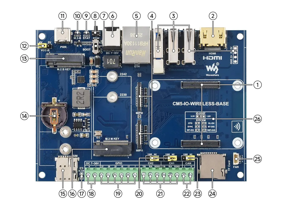
Onboard Resources
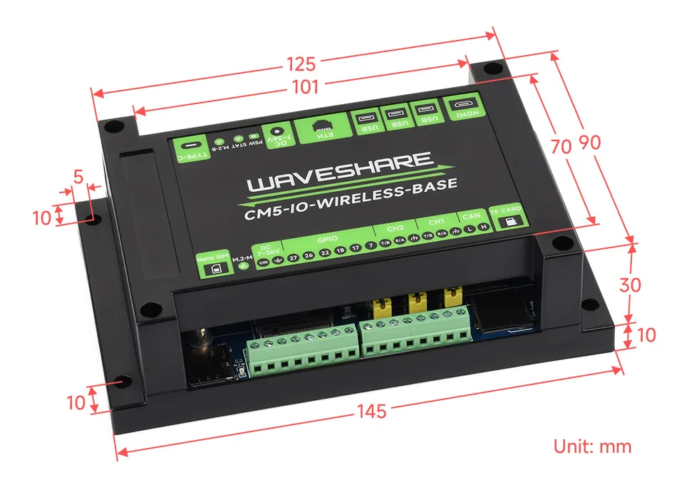
Dimensions
NVMe
This section introduces how to use the NVMe hard drive function on the Raspberry Pi, laying the foundation for subsequent project development.
Note: The PCIe interface must be enabled before using this function.
Enabling the PCIe Interface
- Enabling the PCIe gen3 interface (PCIe gen2 is enabled by default)
- Edit the config.txt filesudo nano /boot/firmware/config.txt
- PCIe defaults to gen2. To enable PCIE gen3, add the following to config.txtdtparam=pciex1_gen=3
- After modification, reboot the Raspberry Pi to recognize the devicesudo reboot
- After reboot, check the PCIe device statuslspci
- Edit the config.txt file

NVMe Hard Drive Operations
Formatting the Hard Drive
- If the PCIe interface is not enabled, enable the PCIe interface first
- Check supported formats. Type
sudo mkfs.and press the tab key to see various suffixes corresponding to different format typessudo mkfs. 
- List all driveslsblk
- To format
/dev/nvme0n1p1as ext4, for example, execute:sudo mkfs.ext4 /dev/nvme0n1p1 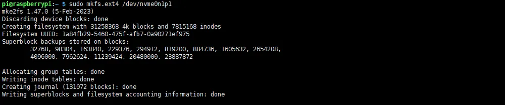
Hard Drive Partitioning
- If the PCIe interface is not enabled, enable the PCIe interface first
- List all drives (use
sudo fdisk -lfor detailed information)lsblk 
- To repartition
/dev/nvme0n1, execute the following command (Note: Use the main device number, not a partition like p1):sudo fdisk /dev/nvme0n1 - Press
nto add a new partition, and finallywto save and exit fdiskcommand functions:nCreate a new partitionqQuit without savingpPrint the partition tablemPrint the menudDelete a partitionwWrite table to disk and exittChange a partition's system ID
Manual Mounting
- If the PCIe interface is not enabled, enable the PCIe interface first
- Confirm the mount directory. Create the directory if it doesn't exist (e.g., to mount to a
toshibafolder in the current directory, create it if missing):sudo mkdir toshiba - List all drives (use
sudo fdisk -lfor detailed information)lsblk 
- To mount
/dev/nvme0n1to thetoshibafolder in the current directory, for example:sudo mount /dev/nvme0n1p1 ./toshiba - Check the file system disk space usagedf -h
Auto-mount on Boot
- Note: Auto-mounting is only used when the drive is not the system disk, i.e., when it functions as additional storage. Perform this configuration only in such cases
- If the PCIe interface is not enabled, enable the PCIe interface first
- Modify the
fstabfilesudo nano /etc/fstab - Add the following line at the end of the file (/dev/nvme0n1p1: device name, /home/pi/toshiba: mount directory, ext4: ilesystem type, defaults uses standard mount options)/dev/nvme0n1p1 /home/pi/toshiba ext4 defaults 0 0
- Apply the changes (Test the mount first to avoid boot issues if the mount fails)sudo mount -a
- If no errors occur, reboot the systemsudo reboot
- After reboot, verify the mount statuslsblk
Read/Write Test
If the PCIe interface is not enabled, enable the PCIe interface first
Check the mount status
lsblkIf mounted correctly, navigate to the mount directory (here /home/pi/toshiba)
cd /home/pi/toshibaCopy data from Raspberry Pi memory to the drive (Write Test)
# Clear memory before the write testsudo sh -c "sync && echo 3 > /proc/sys/vm/drop_caches"sudo dd if=/dev/zero of=./test_write count=2000 bs=1024k
Copy data from the drive to Raspberry Pi memory (Read Test)
# Clear memory before the read testsudo sh -c "sync && echo 3 > /proc/sys/vm/drop_caches"sudo dd if=./test_write of=/dev/null count=2000 bs=1024k
Note: Performance varies depending on the drive and the environment on the Raspberry Pi. Some drives may be speed-limited. For accurate performance testing, use a PC
NVMe Boot
This section introduces how to use NVMe SSD booting on the Raspberry Pi, laying the foundation for subsequent project development.
Note: Do not enable Auto-mount on Boot when booting from an NVMe SSD.
NVMe SSD Boot
Method 1 (Modifying raspi-config)
- First, boot the Raspberry Pi using a TF card, mount and test the NVMe SSD to ensure the hardware functions correctly
- Enter raspi-configsudo raspi-config
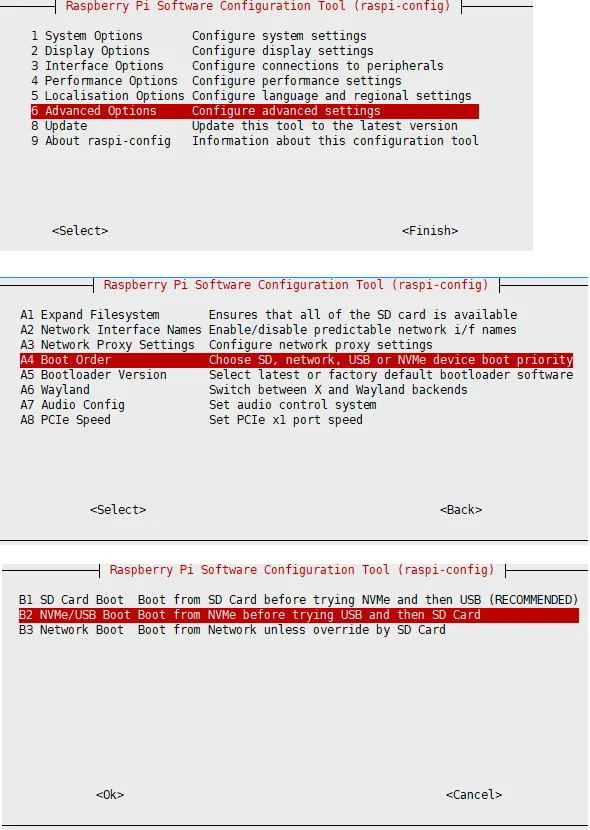
- Reboot the Raspberry Pi (Note: If you find it cannot be modified after multiple attempts, please connect to the network (wait for automatic network time sync) before modifying, or set the correct time before modifying the file)sudo reboot
- Flash the system image to the NVMe SSD, then connect the NVMe SSD to the onboard hard drive interface (or the hard drive interface on the expansion board), remove the TF card, and power on again
Method 2 (Modifying Bootloader Configuration)
- First, boot the Raspberry Pi using a TF card, mount and test the NVMe SSD to ensure the hardware functions correctly
- Enter the bootloader configurationsudo rpi-eeprom-config --edit
- Modify the
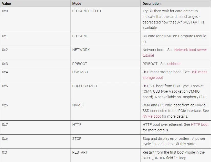
BOOT_ORDERin the Raspberry Pi's bootloader configuration - Change
BOOT_ORDER=0xf41toBOOT_ORDER=0xf416
- Reboot the Raspberry Pi (Note: If you find it cannot be modified after multiple attempts, please connect to the network (wait for automatic network time sync) before modifying, or set the correct time before modifying the file)sudo reboot
- Flash the system image to the NVMe SSD, then connect the NVMe SSD to the onboard hard drive interface (or the hard drive interface on the expansion board), remove the TF card, and power on again
DSI
This section introduces how to use the DSI interface function on the Raspberry Pi, laying the foundation for subsequent project development.
Note: If a DSI configuration is added to config.txt, regardless of whether a DSI screen is connected, the display output will primarily use the DSI interface (i.e., if the DSI configuration is enabled and only an HDMI interface is connected (if the hardware has HDMI), the HDMI will not display the main desktop but will function as an extended display).
Note: The DSI interface is disabled by default and requires configuration in the config.txt file before use.
DSI Interface Selection
- Enable the DSI interface (disabled by default)
- Edit the config.txt filesudo nano /boot/firmware/config.txt
- To use only DSI0 (MIPI0), add the following line:# DSI0 (MIPI0)dtoverlay=vc4-kms-dsi-7inch,dsi0
- To use only DSI1 (MIPI1), add the following line:# DSI1 (MIPI1)dtoverlay=vc4-kms-dsi-7inch,dsi1
- To use both DSI0 (MIPI0) and DSI1 (MIPI1) simultaneously, add following lines:# DSI0 (MIPI0) and DSI1 (MIPI1)dtoverlay=vc4-kms-dsi-7inch,dsi0dtoverlay=vc4-kms-dsi-7inch,dsi1
- After modification, reboot the Raspberry Pi to power on the DSI screen normallysudo reboot
CSI
This section introduces how to use the CSI interface function on the Raspberry Pi, laying the foundation for subsequent project development.
Note: A single camera can only be connected to MIPI0.
Note: The CSI interface is disabled by default and requires configuration in the config.txt file before use.
CSI Interface Selection - Driver Settings
Enable the CSI interface (disabled by default)
Edit the config.txt file
sudo nano /boot/firmware/config.txtAdd the appropriate configuration to config.txt based on the camera model used (examples below use the imx219 driver for cameras):
Camera Driver Model CAM0 Setting Statement CAM1 Setting Statement OV9281 dtoverlay=ov9281,cam0 dtoverlay=ov9281,cam1 IMX290/IMX327 dtoverlay=imx290,clock-frequency=37125000,cam0 dtoverlay=imx290,clock-frequency=37125000,cam1 IMX378 dtoverlay=imx378,cam0 dtoverlay=imx378,cam1 IMX219 dtoverlay=imx219,cam0 dtoverlay=imx219,cam1 IMX477 dtoverlay=imx477,cam0 dtoverlay=imx477,cam1 IMX296 dtoverlay=imx296,cam0 dtoverlay=imx296,cam1 IMX708 dtoverlay=imx708,cam0 dtoverlay=imx708,cam1 To use only CSI0 (MIPI0), add the following line:
# CSI0 (MIPI0)dtoverlay=imx219,cam0To use only CSI1 (MIPI1), add the following line:
# CSI1 (MIPI1)dtoverlay=imx219,cam1To use both CSI0 (MIPI0) and CSI1 (MIPI1) simultaneously, add following lines:
# CSI0 (MIPI0) and CSI1 (MIPI1)dtoverlay=imx219,cam0dtoverlay=imx219,cam1After modification, restart the Raspberry Pi to use the CSI interface to drive the camera normally:
sudo reboot
Camera Detection
- If the CSI interface is not enabled, enable the CSI interface first (Note: The driver settings must match the camera used)
- Use the following command to detect connected cameras:rpicam-hello --list-cameras
- Open the corresponding camera:# Open camera 0rpicam-hello --camera 0 -t 0# Open camera 1rpicam-hello --camera 1 -t 0
- If the camera is detected but fails to start, try updating the system:sudo rpi-update
Displaying Real-time Preview
- If the CSI interface is not enabled, enable the CSI interface first (Note: The driver settings must match the camera used)
- Display the camera preview on the desktop (Note: This command cannot be used over an SSH connection):rpicam-hello -t 0
Taking a Photo
- If the CSI interface is not enabled, enable the CSI interface first (Note: The driver settings must match the camera used)
- Take a photo and save it to the current directory:rpicam-jpeg -o test.jpg
Recording a Video
- If the CSI interface is not enabled, enable the CSI interface first (Note: The driver settings must match the camera used)
- Record a 10-second video and save it to the current directory:rpicam-vid -t 10s -o test.h264
FAN
This section introduces how to use the FAN interface function on the Raspberry Pi, laying the foundation for subsequent project development.
- The fan interface is set to automatic temperature control by default and will adjust its speed automatically based on the core temperature. If you need to set the speed manually, it is recommended to switch back to automatic temperature control mode when manual control is no longer needed.
- Please connect the fan before powering on, otherwise the relevant control commands will be ineffective.
FAN Key Note
- The FAN device on the Raspberry Pi defaults to
/sys/devices/platform/cooling_fan/hwmon/hwmon/pwm1(The fan device is only recognized if connected before powering on)
Manual Speed Control
The fan interface is set to automatic temperature control by default and adjusts its speed based on the core temperature. Setting the speed manually will disable the automatic temperature control function. It is recommended to switch back to automatic mode when manual control is not required.
Control via Commands
Refer to the relevant note: FAN Key Note
Check if the fan device exists (the device exists if the command outputs a listing)
ls /sys/devices/platform/cooling_fan/hwmon/hwmon0Switch to manual control (automatic temperature control is default)
echo 1 | sudo tee /sys/devices/platform/cooling_fan/hwmon/hwmon0/pwm1_enable# sudo echo 1 > /sys/devices/platform/cooling_fan/hwmon/hwmon0/pwm1_enableSet fan speed to 100% (255: fan speed value, range 0~255)
echo 255 | sudo tee /sys/devices/platform/cooling_fan/hwmon/hwmon0/pwm1# sudo echo 255 > /sys/devices/platform/cooling_fan/hwmon/hwmon0/pwm1Set fan speed to 50% (255: fan speed value, range 0~255)
echo 128 | sudo tee /sys/devices/platform/cooling_fan/hwmon/hwmon0/pwm1# sudo echo 128 > /sys/devices/platform/cooling_fan/hwmon/hwmon0/pwm1Set fan speed to 0% (255: fan speed value, range 0~255)
echo 0 | sudo tee /sys/devices/platform/cooling_fan/hwmon/hwmon0/pwm1# sudo echo 0 > /sys/devices/platform/cooling_fan/hwmon/hwmon0/pwm1
Configuration via Initial Settings
By default, the fan on the Pi 5 starts at 50°C. If you want it to start at a different temperature, add the appropriate configuration.
Edit the config.txt file
sudo nano /boot/firmware/config.txtAdd the following lines at the end (
fan_temp0/1/2/3specifies the temperature (36000 means 36°C),fan_temp0/1/2/3_hystis the hysteresis temperature, andfan_temp0/1/2/3_speedis the corresponding speed (maximum 255)):dtparam=fan_temp0=36000,fan_temp0_hyst=2000,fan_temp0_speed=90dtparam=fan_temp1=40000,fan_temp1_hyst=3000,fan_temp1_speed=150dtparam=fan_temp2=52000,fan_temp2_hyst=4000,fan_temp2_speed=200dtparam=fan_temp3=58000,fan_temp3_hyst=5000,fan_temp3_speed=255
View Current Speed
Refer to the relevant note: FAN Key Note
Check if the fan device exists (the device exists if the command outputs a listing)
ls /sys/devices/platform/cooling_fan/hwmon/hwmon0Print the current fan speed
cat /sys/devices/platform/cooling_fan/hwmon/hwmon0/fan1_input
Restore Automatic Temperature Control
Refer to the relevant note: FAN Key Note
Check if the fan device exists (the device exists if the command outputs a listing)
ls /sys/devices/platform/cooling_fan/hwmon/hwmon0Switch to automatic temperature control
echo 2 | sudo tee /sys/devices/platform/cooling_fan/hwmon/hwmon0/pwm1_enable# sudo echo 2 > /sys/devices/platform/cooling_fan/hwmon/hwmon0/pwm1_enable
RTC
This section introduces how to use the RTC function on the Raspberry Pi, laying the foundation for subsequent project development.
To use the full RTC functionality, please connect the RTC battery.
RTC Key Note
- The RTC device on the Raspberry Pi is
/dev/rtc0. - When the RTC device is connected and functioning correctly, if the Raspberry Pi automatically synchronizes time over the network after connecting, then the RTC time will be updated after the automatic network time synchronization
- Newer versions do not have the
hwclockrelated commands installed by default. Please install the necessary tools:sudo apt install -y util-linux-extra
RTC Operations
- The following commands use the
hwclocktool for testing.
Get RTC Time
- If running
hwclockfails, refer to RTC Key Note and execute the installation command. - View RTC time.sudo hwclock -r
- Read the time from a specified RTC device (
-f: followed by the selected device,/dev/rtc0: specifies the RTC device to operate on):sudo hwclock -f /dev/rtc0 -r
Set RTC Time
- If running
hwclockfails, refer to RTC Key Note and execute the installation command - Set the RTC clock time:sudo hwclock --set --date="3/7/2024 16:55:05"
Synchronize RTC Clock
- If running
hwclockfails, refer to RTC Key Note and execute the installation command. - Synchronize the RTC time with the current system time (set the RTC time to the current system time).sudo hwclock -w
- Synchronize the system time with the current RTC time (set the system time to the current RTC time).sudo hwclock -s
Scheduled Shutdown
- Use the
shutdowncommand to automatically shut down the system after a specified time. - Note:
- Shutdown after 10 minutessudo shutdown -h +10
- Automatically shutdown at 23:30 (Note: before this operation, please verify that the current time is correct and whether time resynchronization is needed).sudo shutdown -h 23:30
Scheduled Power-on - Low Power Wake-up
To enable this feature, an RTC battery must be connected to ensure the RTC continues functioning even when external power is disconnected.
- Enter the EEPROM configurationsudo -E rpi-eeprom-config --edit
- Add the following content at the end of the configuration file to enable the scheduled wake-up function:POWER_OFF_ON_HALT=1WAKE_ON_GPIO=0
- After modification, reboot the Raspberry Pi for the changes to take effect:sudo reboot
- You can test the feature using the following method (Effect: after configuration, shut down the system, and the internal RTC will automatically wake up and restart the device after 10 minutes.)
- Set a wake-up alarm 600 seconds (10 minutes) from the current moment:echo +600 | sudo tee /sys/class/rtc/rtc0/wakealarm
- Execute shutdown and wait for the automatic power-on at the scheduled time:sudo halt# or sudo poweroff
- Set a wake-up alarm 600 seconds (10 minutes) from the current moment:
RTC Battery Charging
This operation can only be performed when a rechargeable RTC battery is connected.
- Edit the config.txt filesudo nano /boot/firmware/config.txt
- Add the charging configuration to config.txt (where 3000000 indicates the maximum voltage: charging stops when the voltage reaches 3V; trickle charging starts when the voltage drops below 3V):dtparam=rtc_bbat_vchg=3000000
RS485
This section introduces how to use the RS485 interface functions on the Raspberry Pi, laying the foundation for subsequent project development.
Enabling Interface Configuration
- Enable the RS485 interface (disabled by default)
- Edit the config.txt filesudo nano /boot/firmware/config.txt
- To use RS485, add the following lines (these correspond to the 2 communication interfaces):# Corresponding to CH1dtoverlay=uart4-pi5# Corresponding to CH2dtoverlay=uart2-pi5
- Enable all 4 RS485 channels simultaneously# Enable CH1 ~ CH2 RS485 channels at the same timedtoverlay=uart2-pi5dtoverlay=uart4-pi5
- After modification, reboot the Raspberry Pi, then the program can drive RS485 normallysudo reboot
4G/5G
This section introduces how to use the M.2 B KEY interface functions on the Raspberry Pi, laying the foundation for subsequent project development.
- The test uses the SIM7600. If using other modules, refer to the corresponding 4G/5G module's Wiki.
- The board itself does not support 4G/5G; the module must be connected via the M.2 B KEY interface. The M.2 B KEY interface provides only a USB2.0 channel and does not support PCIe devices.
- To turn off the 4G/5G module, use GPIO6 (BCM pin 6). Output high to disable the module, output low to enable it.
- Enabling or disabling the module takes some time (approximately 30 seconds).
Troubleshooting
No New ttyUSB Device Detected
- Execute the following commands in the terminal to load the USB device descriptors:sudo modprobe optionsudo sh -c 'echo "1e0e 9011" > /sys/bus/usb-serial/drivers/option1/new_id'sudo sh -c 'echo "1e0e 9018" > /sys/bus/usb-serial/drivers/option1/new_id'sudo sh -c 'echo "1e0e 901E" > /sys/bus/usb-serial/drivers/option1/new_id'
Set Up AT Command Configuration Environment
Install the text-based serial communication tool minicom:
sudo apt-get install minicomConnect to the 4G/5G module port (use ttyUSB2, which appears when the module is connected; adjust the port according to your actual situation):
sudo minicom -D /dev/ttyUSB2The following AT commands are common to both 4G and 5G modules:
Command Description Return Value AT Test command OK ATE ATE1 enables echo
ATE0 disables echoOK AT+CGMI Query module manufacturer OK AT+CGMM Query module model OK AT+CGSN Query product serial number OK AT+CSUB Query module version and chip OK AT+CGMR Query firmware version serial number OK AT+IPREX Set module hardware serial port baud rate +IPREX: OK AT+CRESET Reset module OK AT+CSQ Query network signal quality; returns signal value +CSQ: 17,99 OK AT+CPIN? Query SIM card status; returns READY if the SIM card is recognized properly +CPIN: READY AT+COPS? Query current operator; returns operator information when connected to the network +COPS: OK AT+CREG? Query network registration status +CREG: OK AT+CPSI? Query UE system information AT+CNMP Network mode selection command:
2: Automatic
13: GSM only
38: LTE only
48: Any modes but LTE
... ....OK - For more AT commands, refer to: SIM7600 AT Command Reference
- For more documentation, refer to: SIM7600 Reference
ifconfig Fails to Find the Device
- Click here to set up the AT command configuration environment
- Compare the newly added ttyUSB interfaces (if the new interfaces are ttyUSB0~ttyUSB4). If no new ttyUSB device appears, click here to configure.
- Use the newly added ttyUSB interface for configuration changes (here we use the newly added ttyUSB2):sudo minicom -D /dev/ttyUSB2
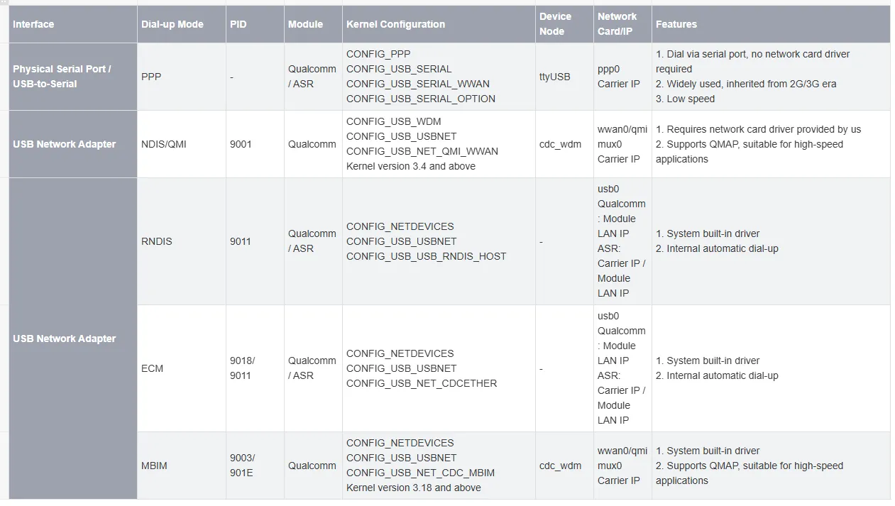
- Enter the following command and press Enter. The module will automatically restart to apply the settings (adjust according to your module's requirements; different modules support different dial-up methods; the example below uses Qualcomm's RNDIS dial-up).
- This command only needs to be set once. On the next power-up, the module will default to this mode (1E0E: Vendor ID, 9011: depends on the actual module):AT+CUSBCFG=USBID,1E0E,9011
- Rescan the devices:
- ifconfig
4G/5G Usage
- Connect the 4G/5G module and the SIM card to the device, then power on.
- Use ifconfig to scan for usb0 (USB network adapter – the exact device name may vary; it is not necessarily usb0). If ifconfig does not find the device, click here to troubleshoot.ifconfig
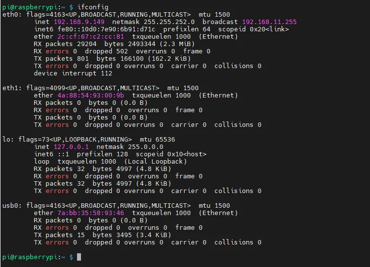
- If the SIM card is properly connected, the NET LED blinks normally but no IP address is obtained, verify that the SIM card is working.
- If the SIM card is working but still no IP address is obtained, execute the following commands in the terminal to renew the IP address:sudo dhclient -v usb0sudo apt-get install udhcpcsudo udhcpc -i usb0sudo route add -net 0.0.0.0 usb0
- Test whether the wireless network card can ping Baidu successfully; be sure to connect the antenna.ping -I usb0 www.baidu.com # Here the port added by the 4G/5G module is usb0; adjust the command according to your actual situation
- If you are using an IoT SIM card that successfully registers on the network but dial-up fails and ping does not work, try one of the following AT commands to select the optimal frequency band (click here to set up the AT command configuration environment):AT+CNBP=0x0002000000400183,0x000001E000000000,0x0000000000000021AT+CNBP=0x0002000000400180,0x480000000000000000000000000000000000000000000042000001E200000095,0x0000000000000021
Lora
This section introduces how to use the Lora function on the Raspberry Pi, laying the foundation for subsequent project development.
- The test uses the SX1303. If using other modules, refer to the corresponding Lora module's Wiki.
- The board itself does not support Lora; it requires an adapter board via the M.2 B KEY interface to connect the Lora module.
Lora Usage
- Various module usage: SX1302 / SX1303
CAN
This section introduces how to use the CAN interface function on the Raspberry Pi, laying the foundation for subsequent project development.
Enabling Interface Configuration
- Enable the CAN interface (disabled by default)
- Edit the config.txt filesudo nano /boot/firmware/config.txt
- To use CAN, add the following lines:dtoverlay=spi0-1cs,cs0_pin=8dtoverlay=mcp2515,spi0-0,oscillator=16000000,interrupt=25
- After modification, reboot the Raspberry Pi to use the CAN driver normally:sudo reboot
- After reboot, use the following command to check the relevant ports; you should see a CAN port:ifconfig
- If the CAN port is DOWN, bring it up (here the device is identified as can0, so the command uses can0; the final 500000 parameter is the CAN bus baud rate in bit/s):sudo ip link set can0 up type can bitrate 500000
- If the CAN port is DOWN, bring it up (here the device is identified as can0, so the command uses can0; the final 500000 parameter is the CAN bus baud rate in bit/s):
- You can also check the relevant devices in the SPI subsystem:dmesg | grep spi

Usage
- Install tools:sudo apt updatesudo apt-get install can-utils
- Send data using cansend (send 0x11 0x22 0x33 0x44; here the hardware is identified as can0, so the command uses can0):cansend can0 000#11.22.33.44
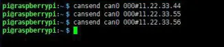
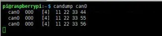
- Listen for CAN data frames using candump (here the device is identified as can0, so the command uses can0):candump can0
Resources
1. Hardware Resources
2. Technical Manuals
- Official CM5 Chip Manuals

[Tutorial Navigation]
- Features
- Onboard Resources
- Dimensions
- NVMe
- NVMe Boot
- DSI
- CSI
- CSI Interface Selection - Driver Settings
- Camera Detection
- Displaying Real-time Preview
- Taking a Photo
- Recording a Video
- FAN
- RTC
- RS485
- 4G/5G
- Troubleshooting
- No New ttyUSB Device Detected
- Set Up AT Command Configuration Environment
- ifconfig Fails to Find the Device
- 4G/5G Usage
- Lora
- CAN
- Resources