


- sales/support
Google Chat:---
- sales
+86-0755-88291180
- sales01
sales@spotpear.com
- sales02
dragon_manager@163.com
- support
tech-support@spotpear.com
- CEO-Complaints
zhoujie@spotpear.com
- Only Tech-Support
WhatsApp:13246739196
- Purchase/Shipping/Refund
WhatsApp:13424403025
- HOME
- >
- ARTICLES
- >
- Common Moudle
- >
- ESP
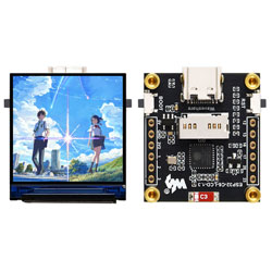
ESP32-C6-LCD-1.3 User Guide
Features
- Low-power SoC equipped with a RISC-V 32-bit single-core processor, operating at up to 160 MHz.
- Supports 2.4GHz Wi-Fi (802.11 b/g/n) and Bluetooth 5 (LE) with an onboard antenna
- Built-in 320 KB SRAM and stacked with 4 MB Flash
- Utilizes a Type-C port, eliminating concerns about plug orientation.
- Onboard 1.3inch LCD screen with 240 × 240 resolution and 262K colors for clear color pictures.
- Built-in ST7789V2 driver chip, using SPI communication to conserve interface pin resources.
- Exposes a 9PIN GPIO interface with 2.54mm pitch for connecting external devices and debugging, enabling flexible peripheral configuration.
Specifications
| MUC | ESP32-C6FH4 | Display Size | 1.3inch |
|---|---|---|---|
| Operating Voltage | 3.3V | Display Resolution | 240x240 pixels |
| Backlight Current | 10mA | Display Panel | IPS |
| Display Interface | 4-wire SPI | Driver IC | ST7789V2 |
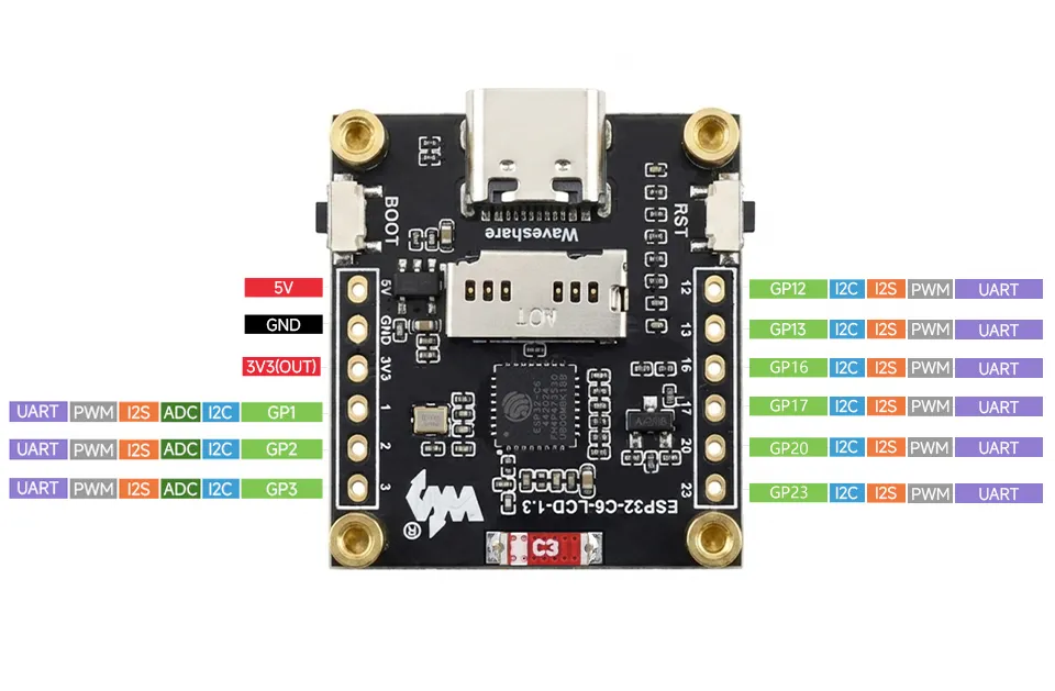
Interface Definition
Supports expansion of various peripherals; more external devices can be connected via the GPIO pin headers.
Onboard Resources
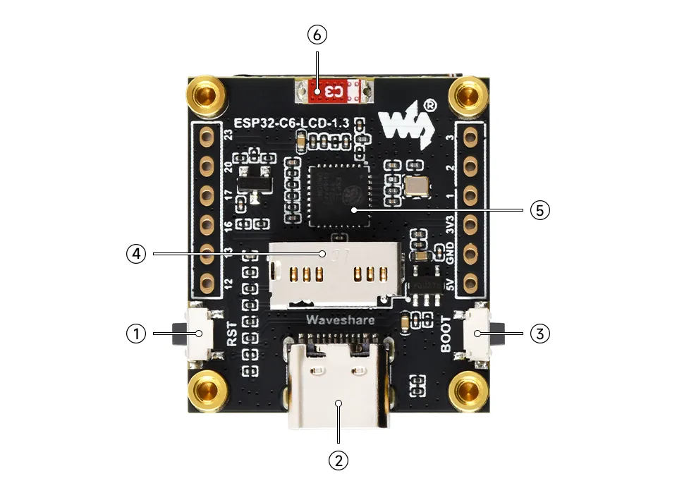
- ① RESET Button
- ② Type-C Interface Used for program flashing and log printing
- ③ BOOT Button Hold the BOOT button while powering on to enter download mode
- ④ TF Card Slot
- ⑤ ESP32-C6 single-core low-power processor, operating at up to 160MHz
- ⑥ Onboard antenna
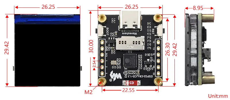
Dimensions
Working with Arduino
This chapter contains the following sections. Please read as needed:
Arduino Getting Started
New to Arduino ESP32 development and looking for a quick start? We have prepared a comprehensive Getting Started Tutorial for you.
- Section 0: Getting to Know ESP32
- Section 1: Installing and Configuring Arduino IDE
- Section 2: Arduino Basics
- Section 3: Digital Output/Input
- Section 4: Analog Input
- Section 5: Pulse Width Modulation (PWM)
- Section 6: Serial Communication (UART)
- Section 7: I2C Communication
- Section 8: SPI Communication
- Section 9: Wi-Fi Basics
- Section 10: Web Server
- Section 11: Bluetooth
- Section 12: LVGL GUI Development
- Section 13: Comprehensive Project
Note: This tutorial uses the ESP32-S3-Zero as a reference example, and all hardware code is based on its pinout. Before you start, we recommend checking the pinout of your development board to ensure the pin configuration is correct.
Setting Up Development Environment
1. Installing and Configuring Arduino IDE
Please refer to the tutorial Installing and Configuring Arduino IDE to download and install the Arduino IDE and add ESP32 support.
2. Installing Libraries
- When installing Arduino libraries, there are typically two methods: Install Online and Install Offline. If the library installation requires Install Offline, you must use the provided library file.
- For most libraries, users can easily search for and install them via the Arduino IDE's online Library Manager. However, some open-source or custom libraries are not synchronized to the Arduino Library Manager and therefore cannot be found through online search. In this case, users can only install these libraries manually via offline methods. You can click this link to download the example package for the ESP32-C6-LCD-1.3 board from the
Arduinodirectory. TheArduino\librariesdirectory within this package contains all the necessary library files required for this tutorial.
| Library/File Name | Description | Version | Installation Method |
|---|---|---|---|
| Adafruit_GFX_Library | Low-level graphics rendering library | v1.11.9 | Install via library manager or manually |
| Arduino_GFX | Display driver graphics library supporting ST7789 chip | v1.4.9 | Install via library manager or manually |
| ArduinoJson | Lightweight JSON parsing/generation library | v6.21.2 | Install via library manager or manually |
| lvgl | LVGL display framework | v8.3.10 | Install via library manager or manually |
| FastLED | Addressable LED control library | v3.10.3 | Install via library manager or manually |
| JPEGDEC | JPEG image decoding library | v1.6.1 | Install via library manager or manually |
| PNGdec | PNG image decoding library | v1.0.2 | Install via library manager or manually |
| Time | Basic time handling library | 1.6.1 | Install via library manager or manually |
| TJpg_Decoder | Ultra-lightweight JPEG decoding library | 1.0.8 | Install via library manager or manually |
There are strong dependencies between versions of LVGL and its driver libraries. For example, a driver written for LVGL v8 may not be compatible with LVGL v9. To ensure that the examples can be reproduced reliably, it is recommended to use the specific versions listed in the table above. Mixing different versions of libraries may lead to compilation failures or runtime errors.
Installation Steps:
Download the example package.
Copy all folders (Arduino_DriveBus, GFX_Library_for_Arduino, etc.) in the
Arduino\librariesdirectory to the Arduino library folder.INFOThe path to the Arduino libraries folder is typically:
c:\Users\<username>\Documents\Arduino\libraries.You can also locate it in the Arduino IDE by going to File > Preferences and checking the "Sketchbook location". The libraries folder is the
librariessubfolder within this path.For other installation methods, please refer to: Arduino Library Management Tutorial.
3. Installing ESP32 Development Board
- To use ESP32-related boards in the Arduino IDE, you must first install the board package "esp32 by Espressif Systems".
- According to board installation requirement''', it is generally recommended to use '''Install Online'''. If online installation fails, use '''Install Offline'''.
- For the installation tutorial, please refer to Arduino Board Management Tutorial
Required Board Installation Instructions for ESP32-C6-LCD-1.3
| Board Name | Installation Requirement | Version Requirement |
|---|---|---|
| ESP32 by Espressif Systems | "Install Offline" / "Install Online" | 3.0.1 |
Example
The Arduino examples are located in the Arduino/examples directory of the example package.
| Demo | Basic Program Description | Dependency Library |
|---|---|---|
| 01_LVGL_Arduino | Demonstrates basic graphics library functions, hardware parameter detection, and display | FastLED, lvgl |
| 02_LVGL_WeatherClock | Demonstrates basic graphics library functions, can also be used to test basic display performance and random text display effects | GFX_Library_for_Arduino, Arduino_DriveBus, Adafruit_XCA9554 |
| 03_Video_demo | Prints ASCII characters in rows and columns on the display according to the screen size | GFX_Library_for_Arduino |
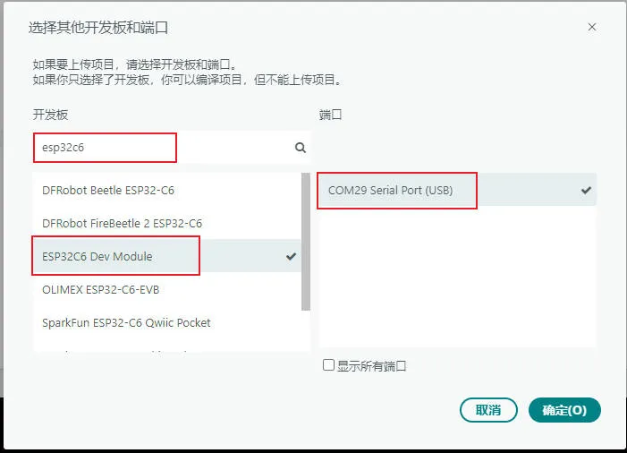
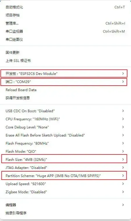
ESP32-C6-LCD-1.3 Model Selection
Arduino Project Parameter Settings
01_LVGL_Arduino
Example Description
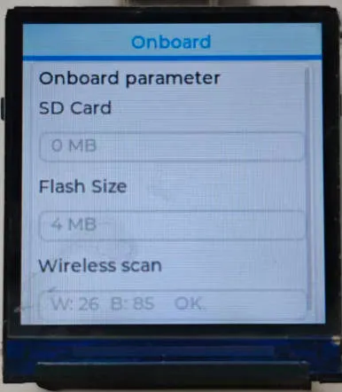
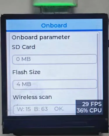
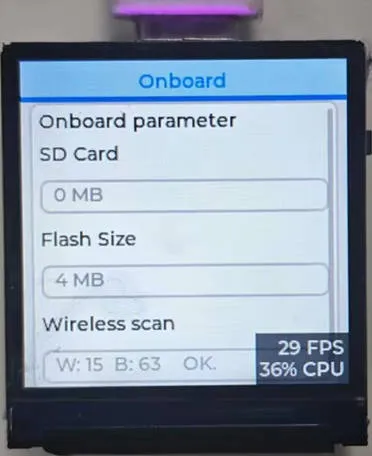
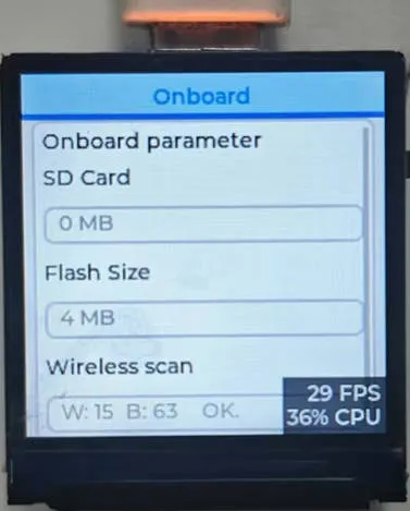
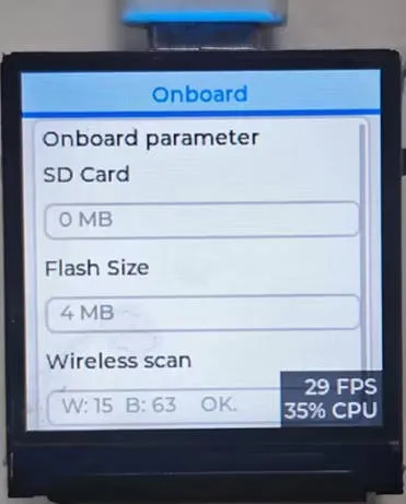
- This example demonstrates displaying hardware information (Flash/TF card capacity, number of scanned wireless devices) through an LVGL graphical interface.
Hardware Connection
- Connect the development board to the computer
Code Analysis
setup()function:Flash_test(): Detects the ESP32 Flash chip capacity and assigns it to the global variableFlash_Size.LCD_Init(): Initializes the ST7789 display (configures SPI, screen commands, backlight, etc.).Lvgl_Init(): Initializes the LVGL graphics library, binds the ST7789 display refresh function, creates a basic LVGL display buffer, and registers touch (placeholder) and display drivers.SD_Init(): Initializes the TF card, detects the card type, calculates the total capacity, and assigns it toSDCard_Size.Lvgl_Example1(): Creates the LVGL interface (Onboard parameter panel), initializes WS2812B and the waterfall light / button.Wireless_Test2(): Creates the FreeRTOS taskWirelessScanTask, which runs in the background on core 0 to scan for WiFi/BLE devices, and stores the results inWIFI_NUM/BLE_NUM.
loop()function:Timer_Loop(): Calls the LVGL core timer handlerlv_timer_handler()to maintain interface refresh and normal execution of timers (such as button detection, waterfall light, parameter refresh).delay(5): A simple delay to ensure LVGL refresh rate.
Operation Result
02_LVGL_WeatherClock
Example Description
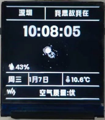
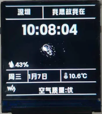
- This example demonstrates a weather clock system, presenting weather clock functionality on the ST7789 display while optimizing for smooth operation and CPU resource usage.
Hardware Connection
- Connect the development board to the computer
Code Analysis
setupfunction:- Serial Initialization: Enables serial communication at 115200 baud for system log printing, facilitating debugging.
- Hardware/Driver Initialization: Executes Flash test, ST7789 display initialization, LVGL graphics library initialization, and TF card initialization in sequence.
- Peripheral Configuration: Sets the display backlight to 100% and initializes the weather clock business logic.
- Log Output: Provides initialization progress feedback via serial, facilitating troubleshooting of startup anomalies.
loopfunction:- LVGL Core Processing: Calls
Timer_Loopto ensure LVGL timers and animations update normally. - Business Logic Loop: Executes
WeatherClock_Loopto handle real-time data updates and display logic for the weather clock. - Resource Optimization: Retains only a 1ms delay, avoiding excessive CPU usage while ensuring high-frequency LVGL scheduling, balancing smoothness and resource consumption.
- LVGL Core Processing: Calls
Operation Result
  |
|---|
03_Video_demo
Example Description
- This example demonstrates TF card detection and video multimedia playback.
Hardware Connection
- Connect the development board to the computer
Code Analysis
setup()function:- Hardware Initialization: Completes Flash test, ST7789 display initialization, backlight setting, and WS2812B LED strip initialization in sequence.
- RGB Self-Test: Sequentially displays red/green/blue colors simultaneously on the screen and LED strip, holding each for 1 second before turning off the LED strip.
- TF Card Detection: Identifies the TF card type. If no card is found, an error message is displayed on the screen and subsequent processes are terminated. If a card is present, it checks for video files. If a video file exists, the video playback module is initialized.
loop()function:- Fallback Logic: If no TF card is detected, only delays in the loop without executing any playback operations.
- Playback Branch: If the video module is initialized, calls
Video_Play_Loop()to play the video in a loop.
Operation Result

Working with ESP-IDF
This chapter includes the following sections, please read as needed:
ESP-IDF Getting Started
New to ESP32 ESP-IDF development and looking to get started quickly? We have prepared a general Getting Started Tutorial for you.
- Section 1: Environment Setup
- Section 2: Running Examples
- Section 3: Creating a Project
- Section 4: Using Components
- Section 5: Debugging
- Section 6: FreeRTOS
- Section 7: Peripherals
- Section 8: Wi-Fi Programming
- Section 9: BLE Programming
Please Note: This tutorial uses the ESP32-S3-Zero as a teaching example, and all hardware code is based on its pinout. Before you start, it is recommended that you check the pinout of your development board to ensure the pin configuration is correct.
Setting Up Development Environment
For the ESP32-C6-LCD-1.3 development board, it is recommended to use ESP-IDF V5.5.0 or higher.
The following guide uses Windows as an example, demonstrating development using VS Code + the ESP-IDF extension. macOS and Linux users should refer to the official documentation.
The screenshots in this section use ESP-IDF V5.5.2 as an example. When installing, please select the ESP-IDF version that matches your board's example.
Install the ESP-IDF Development Environment
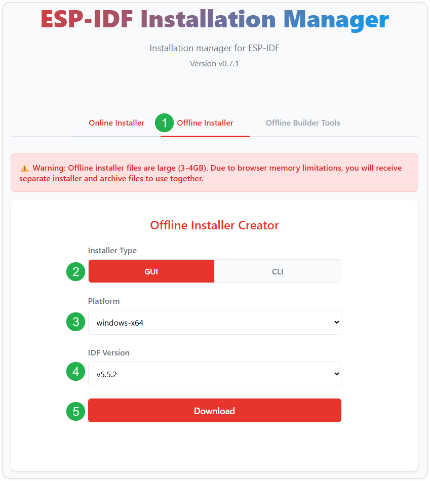
Download the installation manager from the ESP-IDF Installation Manager page. This is Espressif's latest cross-platform installer. The following steps demonstrate how to use its offline installation feature.
Click the Offline Installer tab on the page, then select Windows as the operating system and the ESP-IDF version you need (the version shown in the screenshot is for reference only — choose the version that fits your actual needs).
After confirming your selection, click the download button. The browser will automatically download two files: the ESP-IDF Offline Package (.zst) and the ESP-IDF Installer (.exe).
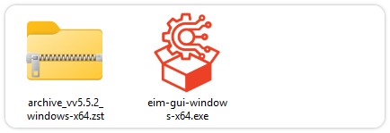
Please wait for both files to finish downloading.
Once the download is complete, double-click to run the ESP-IDF Installer (eim-gui-windows-x64.exe).
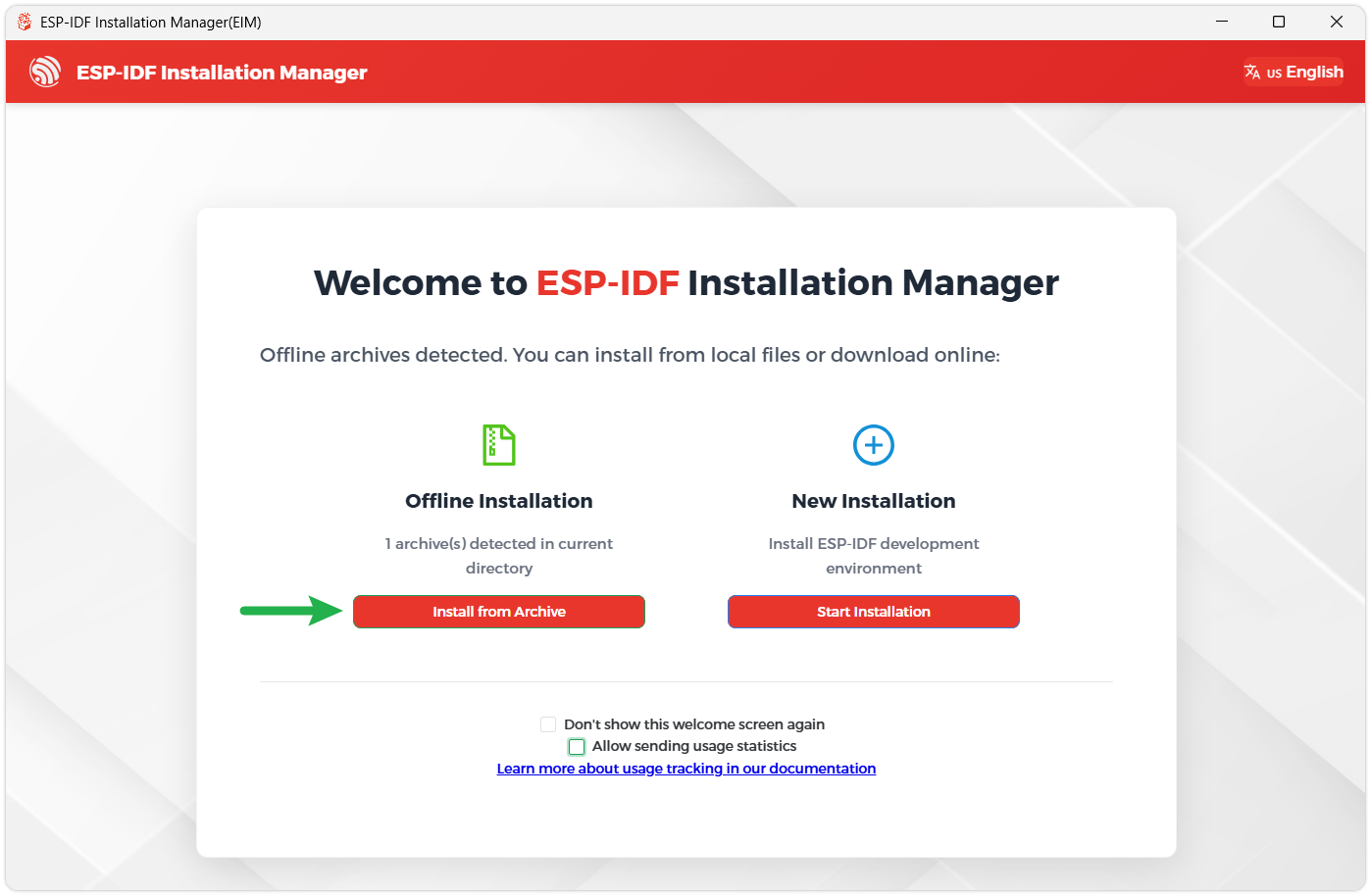
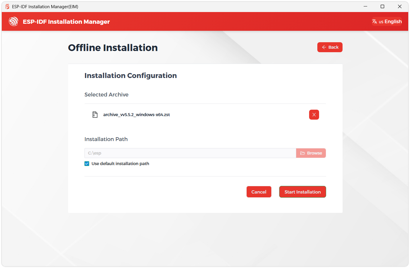
The installer will automatically detect if the offline package exists in the same directory. Click Install from archive.
Next, select the installation path. We recommend using the default path. If you need to customize it, ensure the path does not contain Chinese characters or spaces. Click Start installation to proceed.
When you see the following screen, the ESP-IDF installation is successful.
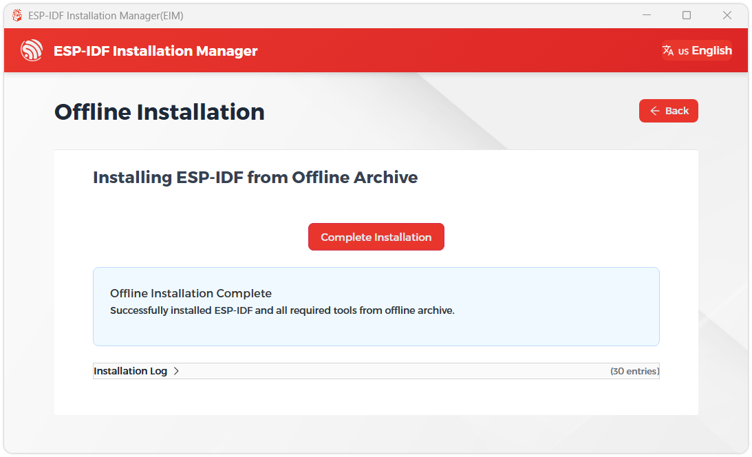
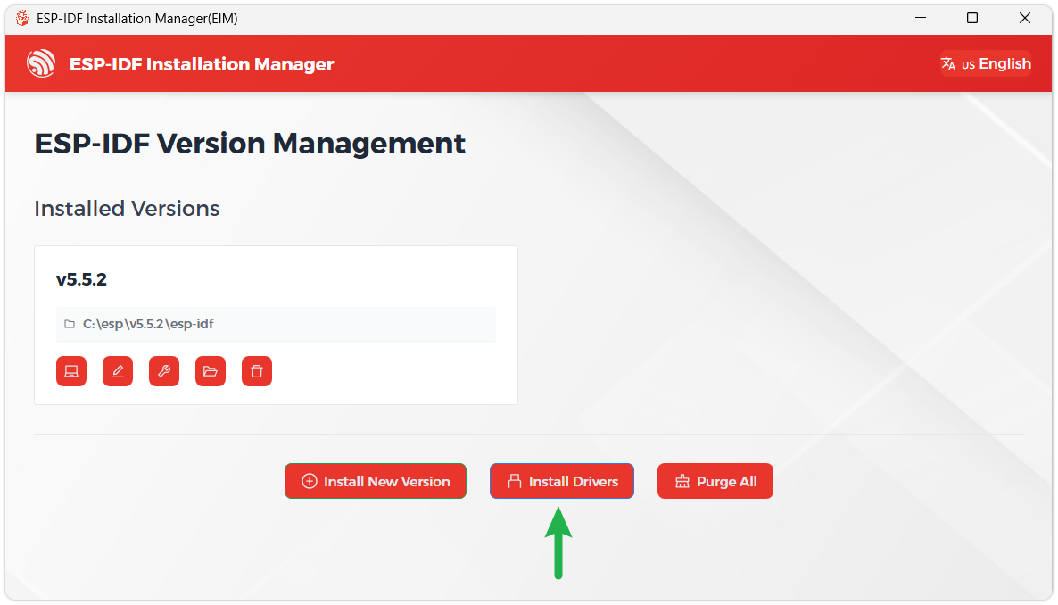
We recommend installing the drivers as well. Click Finish installation, then select Install driver.
Install Visual Studio Code and the ESP-IDF Extension
Download and install Visual Studio Code.
During installation, it is recommended to check Add "Open with Code" action to Windows Explorer file context menu to facilitate opening project folders quickly.
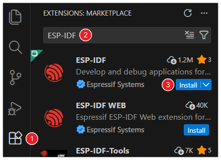
In VS Code, click the Extensions icon
 in the Activity Bar on the side (or use the shortcut Ctrl + Shift + X) to open the Extensions view.
Enter ESP-IDF in the search box, locate the ESP-IDF extension, and click Install.
For ESP-IDF extension versions ≥ 2.0, the extension will automatically detect and recognize the ESP-IDF environment installed in the previous steps, requiring no manual configuration.
Example
01_ESP32-C6-LCD-1.3-Test
Example Description
- This example demonstrates a drawn LVGL interface, with the RGB LED dynamically switching between colors like red, green, yellow, etc., using a breathing light animation effect.
Hardware Connection
- Connect the development board to the computer
Operation Result
- LCD Display: After the device powers on, the LCD lights up automatically, showing the UI interface drawn by LVGL with a stable refresh rate (typically 30-60 fps).
- RGB LED Effect: By default, it displays preset colors. The RGB LED dynamically switches between colors like red, green, yellow, etc., using a breathing light animation effect.
Resources
1. Hardware Resources
2. Technical Manuals
ESP32-C6 Chip Official Manuals
3. Example
Support
Monday-Friday (9:30-6:30) Saturday (9:30-5:30)
Email: services01@spotpear.com
[Tutorial Navigation]
- Features
- Specifications
- Interface Definition
- Onboard Resources
- Dimensions
- Working with Arduino
- Arduino Getting Started
- Setting Up Development Environment
- 1. Installing and Configuring Arduino IDE
- 2. Installing Libraries
- 3. Installing ESP32 Development Board
- Example
- Working with ESP-IDF
- Resources
- Support