


- sales/support
Google Chat:---
- sales
+86-0755-88291180
- sales01
sales@spotpear.com
- sales02
dragon_manager@163.com
- support
tech-support@spotpear.com
- CEO-Complaints
zhoujie@spotpear.com
- Only Tech-Support
WhatsApp:13246739196
- Purchase/Shipping/Refund
WhatsApp:13424403025
- HOME
- >
- ARTICLES
- >
- Common Moudle
- >
- ESP
ESP32-S3-LCD User Guide
Overview
Introduction
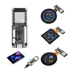
The ESP32-S3-LCD-Driver-Board is a compact-size microcontroller development board with 40Pin 3SPI+RGB565 and 18Pin SPI LCD connectors.
Adopts ESP32-S3-WROOM-1-N8R8 module, which is equipped with Xtensa 32-bit LX7 dual-core processor with 240MHz running frequency, built-in 512KB SRAM (TCM) and 8MB PSRAM; Onboard ETA6096 high-efficiency Lithium battery recharge manager and MX1.25 lithium battery header, adapting 20pin GPIO header which is compatible with 18Pin SPI screen. Supports expanding various peripheral devices and is easy to use.
You can choose Arduino-IDE, ESP-IDF, or other development environments in software so that you can easily and quickly get started and apply it to the product.
Features
- Adopts ESP32-S3-WROOM-1-N8R8 module with Xtensa 32-bit LX7 dual-core processor, capable of running at 240 MHz.
- Integrated 512KB SRAM, 384KB ROM, 8MB PSRAM, 8MB Flash memory.
- Integrated 2.4GHz Wi-Fi and Bluetooth LE dual-mode wireless communication, with superior RF performance.
- Type-C connector, easier to use.
- Onboard 40Pin SPI+RGB and 18Pin SPI LCD screen connector, strong compatibility and expandability.
- Onboard Lithium battery recharge manager ETA6096 and MX1.25 lithium battery header.
- Castellated module allows soldering direct to carrier boards.
- Supports multiple low-power operating states, adjustable balance between communication distance, data rate and power consumption to meet the power requirements of various application scenarios.
Supported Model
| Supported Model | Resolution | LCD Chip | Touch Chip |
| 2.1inch RGB Round Touch Display | 480(H)×480(V) | ST7701 | CST820 |
| 2.8inch RGB Round Touch Display | 480(H)×480(V) | ST7701 | GT911 |
| 4inch RGB Square Touch Display | 480(H)×480(V) | ST7701 | GT911 |
| 2.8inch SPI Square Touch Display | 240(H)×320(V) | ST7789 | CST328 |
Onboard Interface
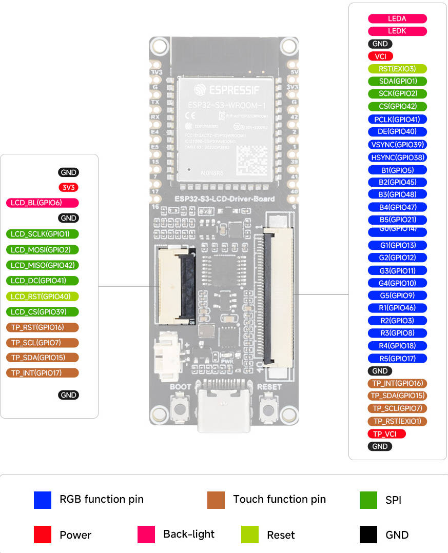
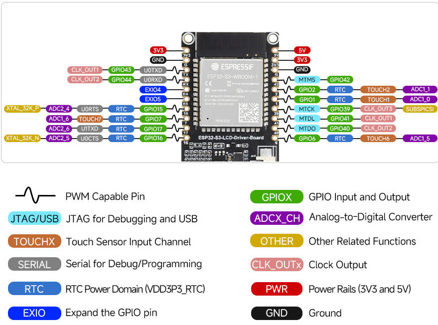
Pinout Definition
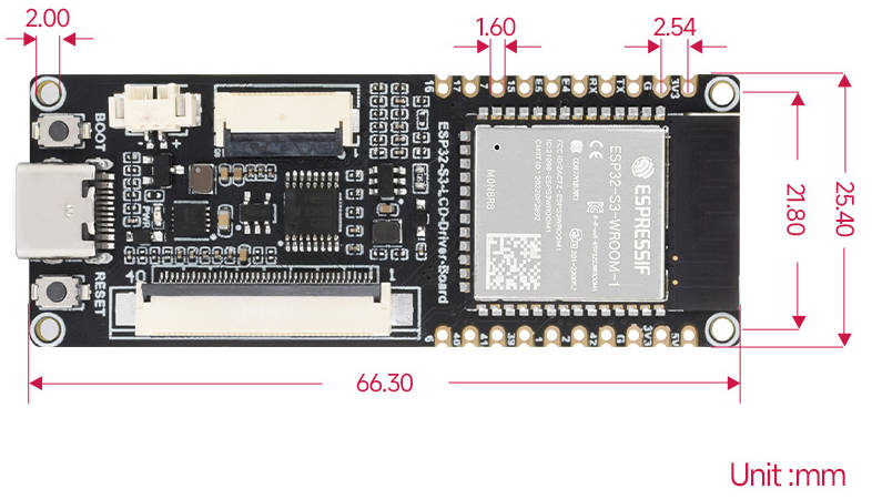
Dimensions
Development Environment Setting
- The following development system is Windows by default.
ESP-IDF
- The following development system is Windows by default, and it is recommended to use VDCode plug-in to develop.
Develop with VSCode Plug-in
Install VSCode
- 1. Open the download page of the official VSCode website, and select the corresponding system and system bit to download.
- 2. After running the installation package, the rest can be installed by default, but here for the subsequent experience, it is recommended to check boxes 1, 2, and 3.
- After the first and second items are enabled, you can open VSCode directly by right-clicking files or directories, which can improve the subsequent user experience.
- After the third item is enabled, you can select VSCode directly when you choose how to open it.
Install Espressif IDF Plug-in
- Note: Currently the latest version of the plugin is V1.6.4, users can choose the same version as us for a consistent experience!
- Open VSCode, use Shift+Ctrl+X to enter the plug-in manager.
- In the search bar, enter Espressif IDF to select the corresponding plug-in and click "Install".
- Press F1 to input:
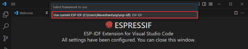
esp-idf: configure esp-idf extension
- Select express (This tutorial is intended for first-time installation users, so only the first general installation tutorial is covered).
- Select download sever.
- Select the version of ESP-IDF you want to use now, we choose the latest V5.1.1.
- The following two are the installation paths respectively for the ESP-IDF container directory and the ESP-IDF Tools directory.
- Note: If you have installed ESP-IDF before, or failed to do so, please be sure to delete the file completely or create a new path without Chinese.
- After configuring, click "Install" to download:
- Enter the download interface, and then it will automatically install the corresponding tools and environment, just wait for a second.
- After the installation is complete, you will enter the following interface, indicating that the installation is finished.
Official Demo Usage Guide
Create Demo
- Press F1 to enter:
esp-idf:show examples projects
- Select your current IDF version:
- Take the Hello World demo as an example:
- ①Select the corresponding demo.
- ②Its readme will state what chip the demo applies to (how the demo is used and the file structure are described below, omitted here).
- ③Click to create the demo.
Select the path to place the demo, no folder with the same name as the demo is required.
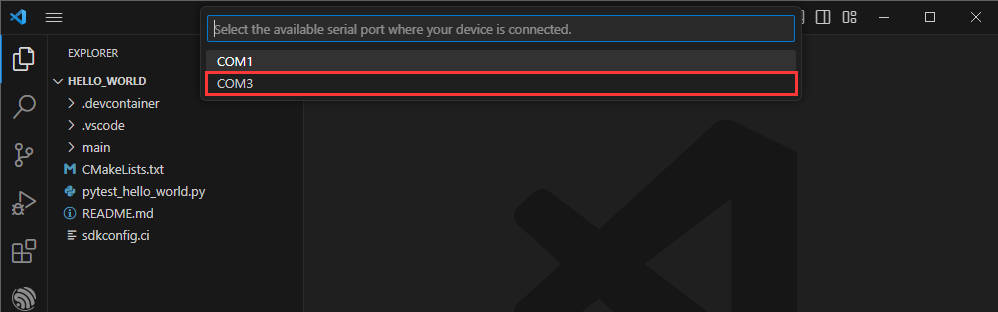
Modify COM Port
- The corresponding COM ports are shown here, click to modify them.
- Please select the COM ports according to your device. (You can view it from the device manager.)
- In case of a download failure, please press the reset button for more than 1 second or enter download mode, and wait for the PC to recognize the device again before downloading once more.
- Select the project or demo to use:
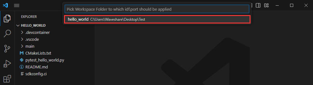
- Then we finish the modification of the COM ports.
Modify the Driver Object
- The driver object is displayed here, and you can modify it by clicking on it.
- Select the project or demo to use.

- Wait for a minute after clicking.
- Select the object we need to drive, which is our main chip, ESP32S3.
- Choose the path to openocd, it doesn't affect us here, so let's just choose one at random.
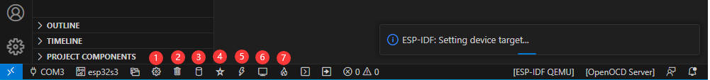
The Rest of the Status Bar
- ①SDK configuration editor, supports modifying many features and configurations of ESP-IDF.
- ②All cleanup, and clear all compiled files.
- ③Compile.
- ④Current download mode, default is UART.
- ⑤Burn the current firmware, please do it after compiling.
- ⑥Open the serial port monitor, used to view the serial port information.
- ⑦Compile, burn, and open the serial monitor all-in-one button, (most commonly used for debugging).
Compile, Program, Serial Port Monitoring
- Click on the all-in-one button we described before to compile, burn, and open the serial port monitor.
- It may take a long time to compile especially for the first time.
- During this process, the ESP-IDF may take up a lot of CPU resources, so it may cause the system to lag.
- If it is the first time to burn the program for a new project, you will need to select the download method, and select UART.
- This can also be changed later in the Download Methods section (click on it to bring up the options).
- As it comes with the onboard automatic download circuit, there is no need for manual operation to download automatically.
- After successful download, automatically enter the serial monitor, you can see the chip output the corresponding information and be prompted to restart after 10S.
Erase Device Flash
- Unpack the software resource package (Flash debugging software).
- Open flash_download_tool_3.9.5.exe software, select ESP32-S3 and USB.
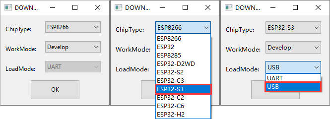
- Select the UART port number, and click START (not select any bin file).
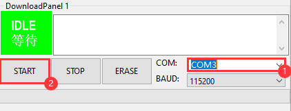
- After programming, click on "ERASE".
- Waiting for Erase to Finish.
Arduino
- Download and install Arduino IDE.
- Install ESP32 on the Arduino IDE as shown below, and you can refer to this link.
- File -> Preferences -> Additional Boards Managers URLs -> Add the following links:
https://espressif.github.io/arduino-esp32/package_esp32_dev_index.json
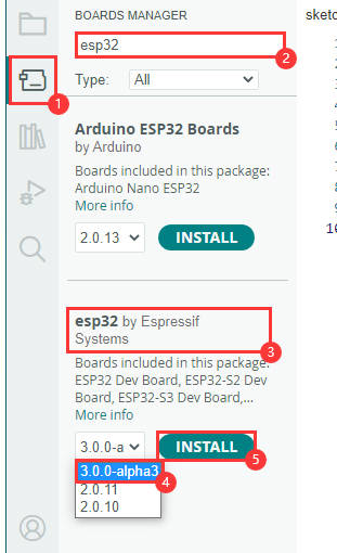
- Enter the development board manager, search for "esp32", select version 3.0.0-alpha3 under "esp32 by Espressif Systems" below, and reboot it after installation.
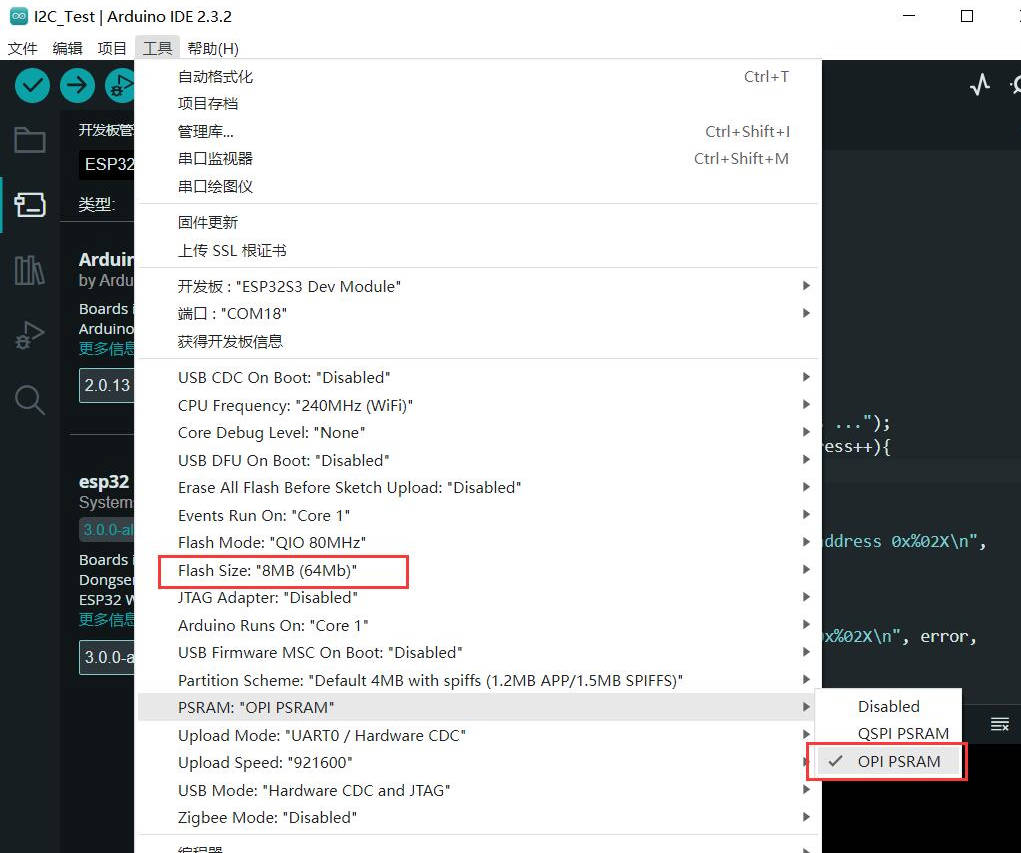
- Open the Arduino IDE and note that Tools in the menu bar selects the corresponding Flash (8MB) and enables PSRAM (8MB OPI)
Use Arduino Demo
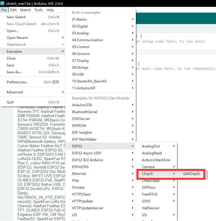
- 1. Select the demo, here we choose the demo to get the chip ID.
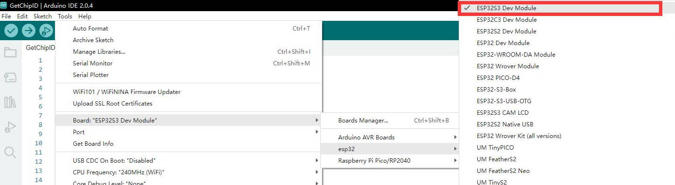
- 2. Select the board as ESP32S3 Dev Module.
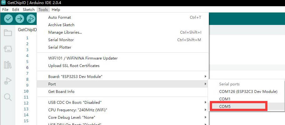
- 3. Choose the COM5 port of ESP32-S3 USB.
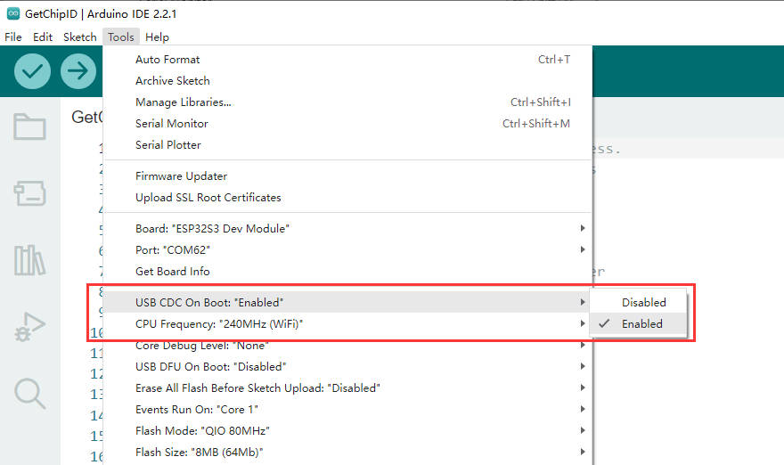
- 4. Enable USB CDC On Boot:
- 5. Click the download button, then it will be compiled and downloaded automatically, if the download fails, please press and hold the boot button to reboot and release the button, then download again.
- 6. Finish.
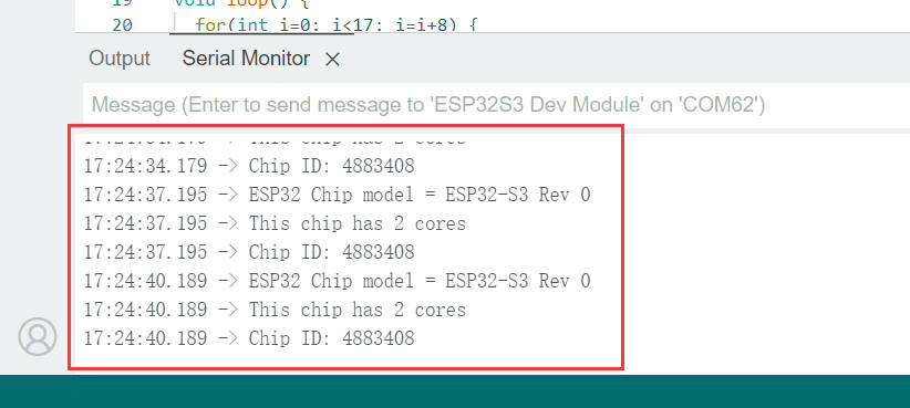
- 7. Open the Serial Port Monitor.
- 8. See the chip ID of the loop output.
Configure Flash & PSRAM
You need to open the Arduino IDE for LCD display, and pay attention to the Tools in the menu bar to select the corresponding Flash (8MB) and enable PSRAM (8MB OPI), as shown in the following figure:
Library Installation
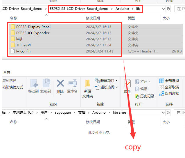
- lvgl libraries require configuration files after installation. It's recommended to directly copy the ESP32_Display_Panel, ESP32_IO_Expander, lvgl file and lv_conf.h file of the resource file to "C:\Users\xxxx\Documents\Arduino\libraries". Please note that "xxxx" represents your computer username.
Arduino Sample Demos
2.8inch_Capacitive_Touch_LCD
2.8inch_Capacitive_Touch_LCD example is for testing 2.8inch Capacitive Touch LCD, and this interface can be connected to 18PIN FPC slot and 13PIN wire. Please ensure the library installation and the Flash and PSRAM configuration are correct.
Hardware Connection
- 13PIN connector:
| LCD PIN | ESP32-S3-LCD-Driver-Board |
| VCC | 3V3 |
| GND | GND |
| MISO | 42 (LCD_MISO) |
| MOSI | 2 (LCD_MOSI) |
| SCLK | 1 (LCD_SCLK) |
| LCD_CS | 39 (LCD_CS) |
| LCD_DC | 41 (LCD_DC) |
| LCD_RST | 40 (LCD_RST) |
| LCD_BL | 6 (LCD_BL) |
| TP_SDA | 15 (TP_SDA) |
| TP_SCL | 7 (TP_SCL) |
| TP_INT | 17 (TP_INT) |
| TP_RST | 16 (TP_RST) |
- 18PIN FPC slot:
Note: Align the "1" and "18" positions of the 18PIN FPC cable connector with the "1" and "18" positions on the 18PIN interface of the ESP32-S3-LCD-Driver-Board when connecting. Do not reverse the connection as it may damage the screen.
Sample Usage
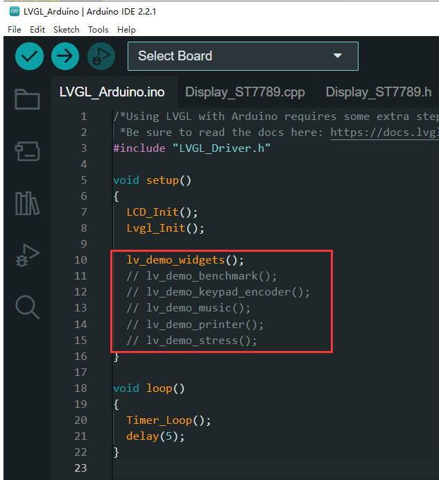
- After correctly configuring the Arduino environment, install our provided library files and open the example:
- Select the development board "ESP32S3 Dev Module" and choose the correct COM port.
- Click compile and upload.
- You can also modify the comments to change the displayed demo.
LVGL_Porting_2.1inch
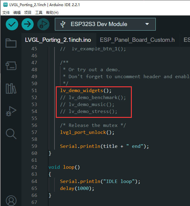
LVGL_Porting_2.1inch is for testing the displaying and touch control of 2.1inch RGB Touch LCD, and you can also modify the comment to replace the demo.
Hardware Connection
- Note: Align the "1" and "40" positions of the 2.1inch LCD with the "1" and "40" positions on the 40PIN interface of the ESP32-S3-LCD-Driver-Board when connecting. Do not reverse the connection as it may damage the screen.
Usage Steps
- After correctly configuring the Arduino environment, open the example:
- Select the development board "ESP32S3 Dev Module" and choose the correct COM port.
- Click compile and upload.
- Observe LCD displaying effect.
- You can also modify the comments to change the displayed demo.
LVGL_Porting_2.8inch
LVGL_Porting_2.8inch is for testing the display and touch control of 2.8inch RGB Touch LCD, and you can also modify the comment to replace the demo.
Hardware Connection
- Note: Align the "1" and "40" positions of the 2.8inch LCD with the "1" and "40" positions on the 40PIN interface of the ESP32-S3-LCD-Driver-Board when connecting. Do not reverse the connection as it may damage the screen.
Usage Steps
- After correctly configuring the Arduino environment, open the example:
- Select the development board "ESP32S3 Dev Module" and choose the correct COM port.
- Click compile and upload.
- Observe LCD displaying effect.
- You can also modify the comments to change the displayed demo.
LVGL_Porting_4inch
LVGL_Porting_4inch example is for testing the display effect and touch control of 4inch RGB Touch LCD, and you can also modify the comment to replace the demo.
Hardware Connection
- Note: Align the "1" and "40" positions of the 4inch LCD with the "1" and "40" positions on the 40PIN interface of the ESP32-S3-LCD-Driver-Board when connecting. Do not reverse the connection as it may damage the screen.
Usage Steps
- After correctly configuring the Arduino environment, open the example:
- Select the development board "ESP32S3 Dev Module" and choose the correct COM port.
- Click compile and upload.
- Observe LCD displaying effect.
- You can also modify the comments to change the displayed demo.
ESP-IDF Sample Demos
2.1inch_RGB_LCD
2.1inch_RGB_LCD is for testing the usage of 2.1inch RGB LCD, and it also drives the display and touch control of 2.1inch RGB LCD.
Hardware Connection
- Note: Align the "1" and "40" positions of the 2.1inch LCD with the "1" and "40" positions on the 40PIN interface of the ESP32-S3-LCD-Driver-Board when connecting. Do not reverse the connection as it may damage the screen.
Usage Steps
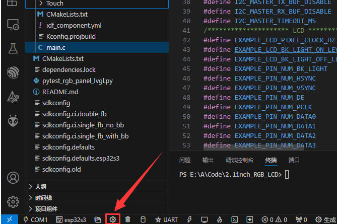
- After correctly configuring the vscode environment, open the example:
- Click compile and download.
- Observe LCD displaying effect.
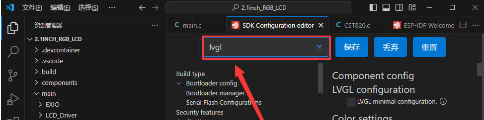
- You can also modify the display demo through menuconfig:
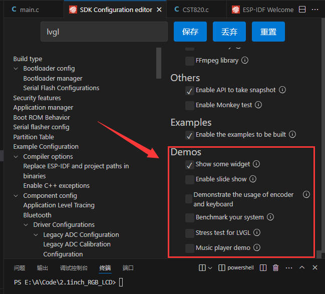
4. Save it, and then compile and download it again.
2.8inch_RGB_LCD
2.1inch_RGB_LCD demo is for testing 2.1inch RGB LCD, and it also drives the displaying and touch control of the 2.1inch RGB LCD.
Hardware Connection
- Note: Align the "1" and "40" positions of the 2.8inch LCD with the "1" and "40" positions on the 40PIN interface of the ESP32-S3-LCD-Driver-Board when connecting. Do not reverse the connection as it may damage the screen.
Usage Steps
- After correctly configuring the vscode environment, open the example:
- Click compile and download.
- Click on menuconfig, search for lvgl, and then modify lvgl demo. Save the modification, and then compile and download again (for more details, you can refer to 2.1inch RGB LCD).
4inch_RGB_LCD
4inch_RGB_LCD demo is for testing 4inch RGB LCD and also drives the displaying and touch control of the 4inch RGB LCD.
Hardware Connection
- Note: Align the "1" and "40" positions of the 4inch LCD with the "1" and "40" positions on the 40PIN interface of the ESP32-S3-LCD-Driver-Board when connecting. Do not reverse the connection as it may damage the screen.
Usage Steps
- After correctly configuring the vscode environment, open the example:
- Click compile and download.
- Click on menuconfig, search for lvgl, and then modify the lvgl demo. Save the modification, and then compile and download again (for more details, you can refer to 2.1inch RGB LCD).
2.1inch_RGB_LCD_pic
2.1inch_RGB_LCD_pic demo is for 2.1inch RGB LCD to display pictures.
Hardware Connection
- Note: Align the "1" and "40" positions of the 2.1inch LCD with the "1" and "40" positions on the 40PIN interface of the ESP32-S3-LCD-Driver-Board when connecting. Do not reverse the connection as it may damage the screen.
Usage Steps
- After correctly configuring the vscode environment, open the example:
- Click compile and download.
- Modify the "test1.c" file to change the pictures to display.
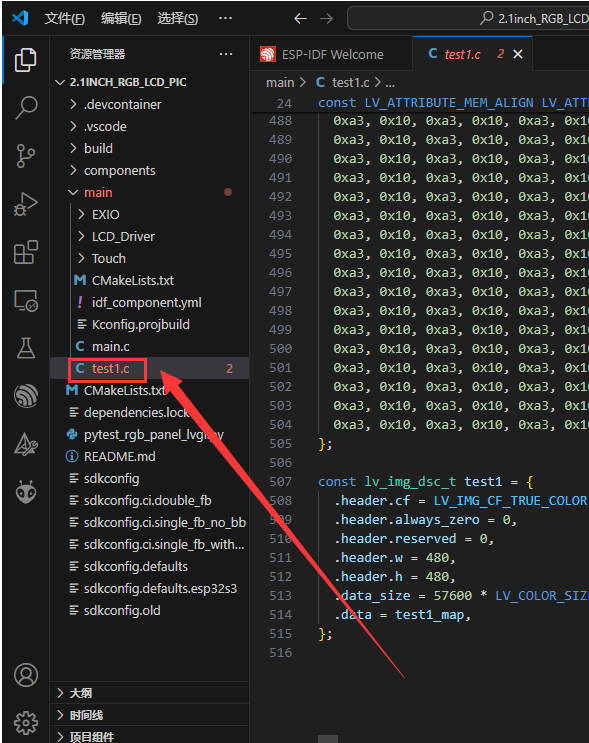
As the screen resolution is 480×480, the pictures you use should be the same as this resolution, and you can also convert pictures to "c" file through LVGL Online Image Converter.
After replacing the original file with the newly generated image file, open the new image file for editing.
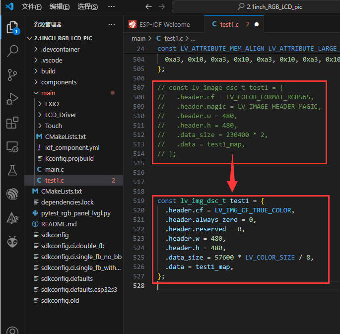
const lv_img_dsc_t test1 = {
  .header.cf = LV_IMG_CF_TRUE_COLOR,
  .header.always_zero = 0,
  .header.reserved = 0,
  .header.w = 480,
  .header.h = 480,
  .data_size = 57600 * LV_COLOR_SIZE / 8,
  .data = test1_map,
};
2.8inch_RGB_LCD_pic
2.8inch_RGB_LCD_pic is for testing 2.8inch RGB LCD to display pictures.
Hardware Connection
- Note: Align the "1" and "40" positions of the 2.8inch LCD with the "1" and "40" positions on the 40PIN interface of the ESP32-S3-LCD-Driver-Board when connecting. Do not reverse the connection as it may damage the screen.
Usage Steps
- After correctly configuring the vscode environment, open the example:
- Click compile and download.
- Modify the "test2.c" file to change the pictures to display (for more details, you can refer to #2.1inch_RGB_LCD_pic).
Modify the demo as shown below:
const lv_img_dsc_t test2 = {
  .header.cf = LV_IMG_CF_TRUE_COLOR,
  .header.always_zero = 0,
  .header.reserved = 0,
  .header.w = 480,
  .header.h = 480,
  .data_size = 57600 * LV_COLOR_SIZE / 8,
  .data = test2_map,
};
4inch_RGB_LCD_pic
4inch_RGB_LCD_pic is for testing 4inch RGB LCD to display pictures.
Hardware Connection
- Note: Align the "1" and "40" positions of the 4inch LCD with the "1" and "40" positions on the 40PIN interface of the ESP32-S3-LCD-Driver-Board when connecting. Do not reverse the connection as it may damage the screen.
Usage Steps
- After correctly configuring the vscode environment, open the example:
- Click compile and download.
- Modify the "test3.c" file to change the pictures to display. (for more details, you can refer to #2.1inch_RGB_LCD_pic)
Modify the demo as shown below:
const lv_img_dsc_t test3 = {
  .header.cf = LV_IMG_CF_TRUE_COLOR,
  .header.always_zero = 0,
  .header.reserved = 0,
  .header.w = 480,
  .header.h = 480,
  .data_size = 57600 * LV_COLOR_SIZE / 8,
  .data = test3_map,
};
Resource
Schematic
Demo
Software
Arduino
CH343
Serial Port
Datasheet
ESP32-S3
ESP32 Official Document
FAQ
Check if the power supply voltage of the USB port is less than 5V. Generally, the power supply voltage of the USB port is above 4.9V. Both USB ports of the module can be used normally. If it is lower than 4.9V, there may be insufficient power supply, causing the USB port to disconnect. In this case, replace it with a USB port that provides sufficient voltage.
When flashing the demo, you can press and hold the Boot button, insert the USB, and then release the button to enter Download mode before starting to flash the demo. After flashing, unplug and reinsert the USB to enter SPI_FAST_FLASH_BOOT mode to run the demo.
When using Arduino's LVGL demo, the time taken to compile and upload is long because the Arduino IDE compiles the program during upload. Since the LVGL library has many files to compile, it will take a relatively long time. Please be patient.
Ensure that the IDF demo path does not contain any Chinese characters, as this can cause retrieval errors.
If there is no response from the screen after burning the code, check if the correct settings are configured in Arduino IDE -> Tools: Select the corresponding Flash (8MB) and enable PSRAM (8MB OPI).
Support
Monday-Friday (9:30-6:30) Saturday (9:30-5:30) -China time
Email: services01@spotpear.cn
[Tutorial Navigation]
- Overview
- Development Environment Setting
- ESP-IDF
- Develop with VSCode Plug-in
- Install Espressif IDF Plug-in
- Official Demo Usage Guide
- Create Demo
- Modify COM Port
- Modify the Driver Object
- The Rest of the Status Bar
- Compile, Program, Serial Port Monitoring
- Erase Device Flash
- Arduino
- Arduino Sample Demos
- ESP-IDF Sample Demos
- Resource
- FAQ
- Question:After powering on the module, the recognized serial port device and USB port keep resetting and restarting. What should I do?
- Question:After downloading a demo to the module, sometimes it fails to connect to the serial port or fails to flash the demo when re-downloading. What should I do?
- Question:Why does the Arduino LVGL demo take a long time to compile and burn?
- Question:What should I do if there is a compilation error with the ESP-IDF demo?
- Question: What should I do if the Arduino de,o burns successfully but the screen does not display anything?
- Support