




- sales/support
Google Chat:---
- sales
+86-0755-88291180
- sales01
sales@spotpear.com
- sales02
dragon_manager@163.com
- support
tech-support@spotpear.com
- CEO-Complaints
zhoujie@spotpear.com
- Only Tech-Support
WhatsApp:13246739196
- Purchase/Shipping/Refund
WhatsApp:13424403025
- HOME
- >
- ARTICLES
- >
- Common Moudle
- >
- ESP
ESP32-C3-LCD-1.47 User Guide
Features
- Equipped with the ESP32-C3FH4 controller chip, featuring a RISC-V 32-bit single-core low‑power SoC, running at up to 160 MHz
- Supports 2.4GHz Wi‑Fi (802.11 b/g/n) and Bluetooth BLE 5 wireless communication
- Built‑in 400KB SRAM and 384KB ROM, with stacked 4MB Flash
- Onboard ceramic antenna for easy integration into custom baseboards or embedded devices
- Integrated full‑speed USB serial controller for convenient program download and debugging
- 15 GPIOs brought out for flexible peripheral expansion
- Rich peripherals resources including 3 × SPI, 1 × I2C, 2 × UART, 1 × I2S, 2 × ADC, etc.
Specifications
| Parameter | Value |
|---|---|
| Interface | USB Type‑C |
| Main Controller | ESP32-C3FH4 |
| Screen Type | ISP |
| Screen Resolution | 172 × 320 |
| Display Chip | ST7798 |
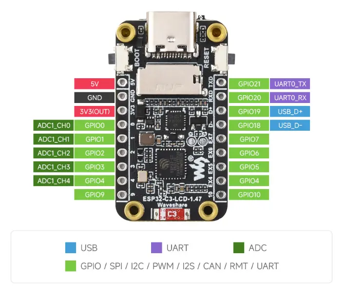
Interface Introduction
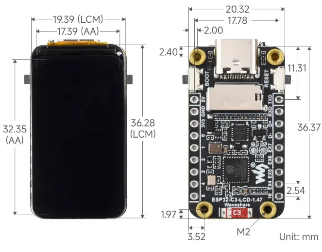
Dimensions
Working with Arduino
This chapter contains the following sections. Please read as needed:
Arduino Getting Started
New to Arduino ESP32 development and looking for a quick start? We have prepared a comprehensive Getting Started Tutorial for you.
- Section 0: Getting to Know ESP32
- Section 1: Installing and Configuring Arduino IDE
- Section 2: Arduino Basics
- Section 3: Digital Output/Input
- Section 4: Analog Input
- Section 5: Pulse Width Modulation (PWM)
- Section 6: Serial Communication (UART)
- Section 7: I2C Communication
- Section 8: SPI Communication
- Section 9: Wi-Fi Basics
- Section 10: Web Server
- Section 11: Bluetooth
- Section 12: LVGL GUI Development
- Section 13: Comprehensive Project
Note: This tutorial uses the ESP32-S3-Zero as a reference example, and all hardware code is based on its pinout. Before you start, we recommend checking the pinout of your development board to ensure the pin configuration is correct.
Setting Up the Development Environment
1. Installing and Configuring the Arduino IDE
Please refer to the tutorial Installing and Configuring Arduino IDE to download and install the Arduino IDE and add ESP32 support.
2. Installing Libraries
- When installing Arduino libraries, there are typically two methods: online installation and offline installation. If the library installation requires offline installation, you must use the provided library files.
- For most libraries, users can easily search for and install them via the Arduino IDE's online Library Manager. However, some open-source or custom libraries are not synchronized to the Arduino Library Manager and therefore cannot be found through online search. In this case, users can only install these libraries manually via offline methods. =
| Library or File Name | Description | Version | Installation Method |
|---|---|---|---|
| LVGL | Graphics library | v8.4.0 | "Online Installation" |
| JPEGDEC | JPEG decoder library | v1.8.4 | "Online Installation" |
| GFX_Library_for_Arduino | LCD driver library | v1.5.9 | "Online Installation" |
There are strong dependencies between versions of LVGL and its driver libraries. For example, a driver written for LVGL v8 may not be compatible with LVGL v9. To ensure that the examples can be reproduced reliably, it is recommended to use the specific versions listed in the table above. Mixing different versions of libraries may lead to compilation failures or runtime errors.
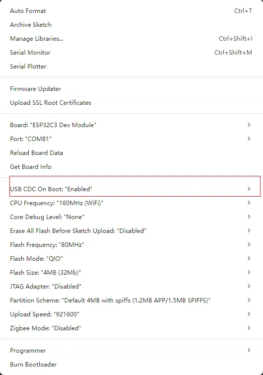
3. Arduino Project Parameter Settings
Example
The Arduino examples are located in the Arduino/examples directory of the example package.
| Example | Basic Description | Dependent Libraries | Version |
|---|---|---|---|
| 01_gfx_helloworld | Display HelloWorld on the screen | GFX_Library_for_Arduino | |
| 02_sd_card_test | Test TF card | JPEGDEC | - |
| 03_Brightness | Control backlight using buttons | LVGL | 8.4.0 |
| 04_LVGL | Run LVGL benchmark example | LVGL | 8.4.0 |
01_gfx_helloworld
Example Description
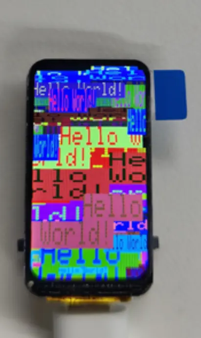
- This example demonstrates the ESP32-C3-LCD-1.47 using the GFX_Library_for_Arduino library to drive the screen and display "HelloWorld".
Hardware Connection
- Connect the board to the computer using a USB cable.
Code Analysis
loop(): Continuously refreshes the displayed content, printing a line of text at random positions, colors, and font sizes each time.gfx->setCursor(): Sets the starting coordinates for this text output.gfx->setTextColor(): Sets the foreground/background color (random values are used here to make the refresh effect observable).gfx->setTextSize(): Sets the font size scaling factor (randomly varied).gfx->println("Hello World!")/delay(1000): Outputs the text and delays for 1 second, creating a dynamic animated demonstration.
  void loop(void)
  {
    gfx->setCursor(random(gfx->width()), random(gfx->height()));
    gfx->setTextColor(random(0xffff), random(0xffff));
    gfx->setTextSize(random(6), random(6), random(2));
    gfx->println("Hello World!");
    delay(1000);
  }
Operation Result
HelloWorld is displayed on the screen.
02_SD
Example Description
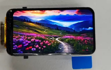
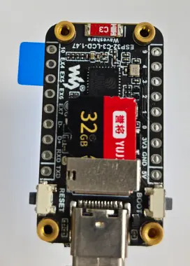
- This example demonstrates the ESP32-C3-LCD-1.47 reading a JPG image from the TF card and displaying it on the screen.
Hardware Connection
- Connect the board to the computer.
- Insert the TF card into the card slot (the TF card needs to be formatted as FAT32).
- Place the image
image_01.jpgin the root directory of the TF card.
Code Analysis
jpgPath: The path to the JPG file to be displayed (found in the TF card root directory).Serial.printf("draw: %s\r\n", jpgPath): Outputs the filename to be drawn to the serial port, making it easy to confirm the correct image is read.gfx->fillScreen(RGB565_BLACK): Clears the screen before drawing to avoid residual images or frame stacking.Serial.printf("draw: %s\r\n", jpgPath);gfx->fillScreen(RGB565_BLACK);
Operation Result
- After flashing, the image is displayed on the screen.
03_Brightness
Example Description
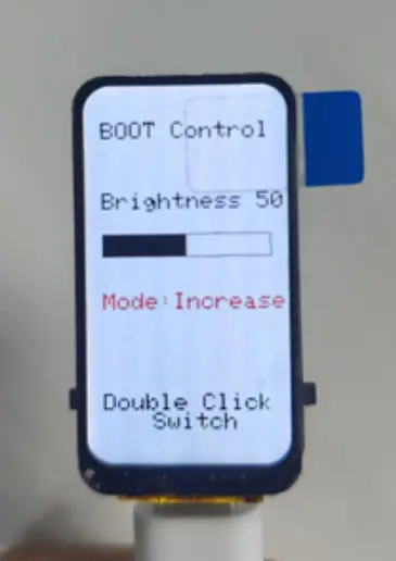
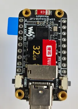
- This example demonstrates controlling the screen brightness using the BOOT button. Double‑clicking the BOOT button switches the control logic.
Hardware Connection
- Connect the board to the computer.
Code Analysis
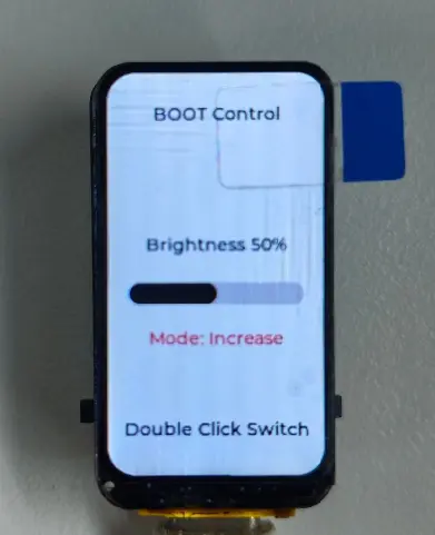
gfx->fillScreen(RGB565_WHITE): Clears the screen and sets the UI background color.gfx->printf("Brightness %u%%", backlight): Outputs the current backlight percentage to the screen.drawBarFrame()/drawBarValue(): Draws the brightness bar border and the current brightness fill, providing an intuitive visualization of brightness changes.increase ? ... : ...: Displays the current mode ("Increase/Decrease") based on the control logic, using red/green for distinction.
  gfx->fillScreen(RGB565_WHITE);
  gfx->setTextColor(RGB565_BLACK, RGB565_WHITE);
  gfx->setTextSize(2);
  gfx->setCursor(18, 30);
  gfx->println("BOOT Control");

  gfx->setCursor(18, 90);
  gfx->printf("Brightness %u%%", backlight);

  drawBarFrame(18, 125, 144, 20);
  drawBarValue(18, 125, 144, 20, backlight);

  gfx->setCursor(18, 175);
  gfx->setTextColor(increase ? RGB565_RED : RGB565_GREEN, RGB565_WHITE);
  gfx->println(increase ? "Mode: Increase" : "Mode: Decrease");

  gfx->setCursor(18, 260);
  gfx->setTextColor(RGB565_BLACK, RGB565_WHITE);
  gfx->println("Double Click Switch");
Operation Result
04_LVGL
Example Description
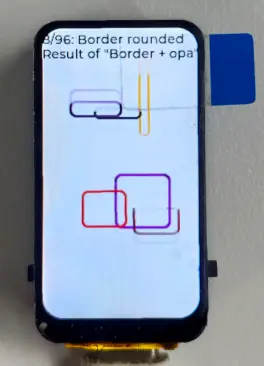
- This example demonstrates the ESP32-C3-LCD-1.47 running the LVGL benchmark example.
  Serial.begin(115200);
  delay(50);
  Serial.println("ESP32_C3_LCD_1in47 LVGL example");

  if (!lcd.begin()) {
    Serial.printf("lcd.begin failed: %s\r\n", esp_err_to_name(lcd.lastError()));
    while (true) {
      delay(1000);
    }
  }

  gfx = lcd.gfx();
  gfx->fillScreen(RGB565_BLACK);

  if (!initLvgl()) {
    Serial.println("LVGL init failed");
    gfx->setCursor(8, 8);
    gfx->setTextColor(RGB565_RED);
    gfx->println("LVGL init failed");
    while (true) {
      delay(1000);
    }
  }
Code Analysis
Serial.begin(115200): Initializes the serial port for outputting runtime logs and error messages.lcd.begin(): Initializes the LCD driver and low‑level bus; on failure, prints an error and halts in awhile (true)loop to prevent further abnormal execution.gfx = lcd.gfx()/gfx->fillScreen(RGB565_BLACK): Obtains the graphics library handle and clears the screen to prepare an initial canvas for subsequent UI drawing.initLvgl(): Initializes LVGL (display buffer/driver registration, etc.); on failure, displays a prompt on the screen and enters awhile (true)loop to preserve the state for troubleshooting.
Operation Result
ESP-IDF
This chapter contains the following sections. Please read as needed:
ESP-IDF Getting Started
New to ESP32 ESP-IDF development and looking to get started quickly? We have prepared a general Getting Started Tutorial for you.
- Section 1: Environment Setup
- Section 2: Running Examples
- Section 3: Creating a Project
- Section 4: Using Components
- Section 5: Debugging
- Section 6: FreeRTOS
- Section 7: Peripherals
- Section 8: Wi-Fi Programming
- Section 9: BLE Programming
Please Note: This tutorial uses the ESP32-S3-Zero as a teaching example, and all hardware code is based on its pinout. Before you start, it is recommended that you check the pinout of your development board to ensure the pin configuration is correct.
Setting Up the Development Environment
For the ESP32-C3-LCD-1.47 development board, ESP-IDF version V5.5.0 or above is required.
The following guide uses Windows as an example, demonstrating development using VS Code + the ESP-IDF extension. macOS and Linux users should refer to the official documentation.
The screenshots in this section use ESP-IDF V5.5.2 as an example. When installing, please select the ESP-IDF version that matches your board's example.
Install the ESP-IDF Development Environment
Download the installation manager from the ESP-IDF Installation Manager page. This is Espressif's latest cross-platform installer. The following steps demonstrate how to use its offline installation feature.
Click the Offline Installer tab on the page, then select Windows as the operating system and the ESP-IDF version you need (the version shown in the screenshot is for reference only — choose the version that fits your actual needs).
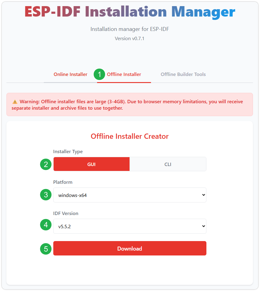
After confirming your selection, click the download button. The browser will automatically download two files: the ESP-IDF Offline Package (.zst) and the ESP-IDF Installer (.exe).
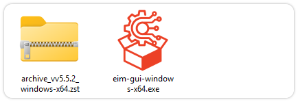
Please wait for both files to finish downloading.
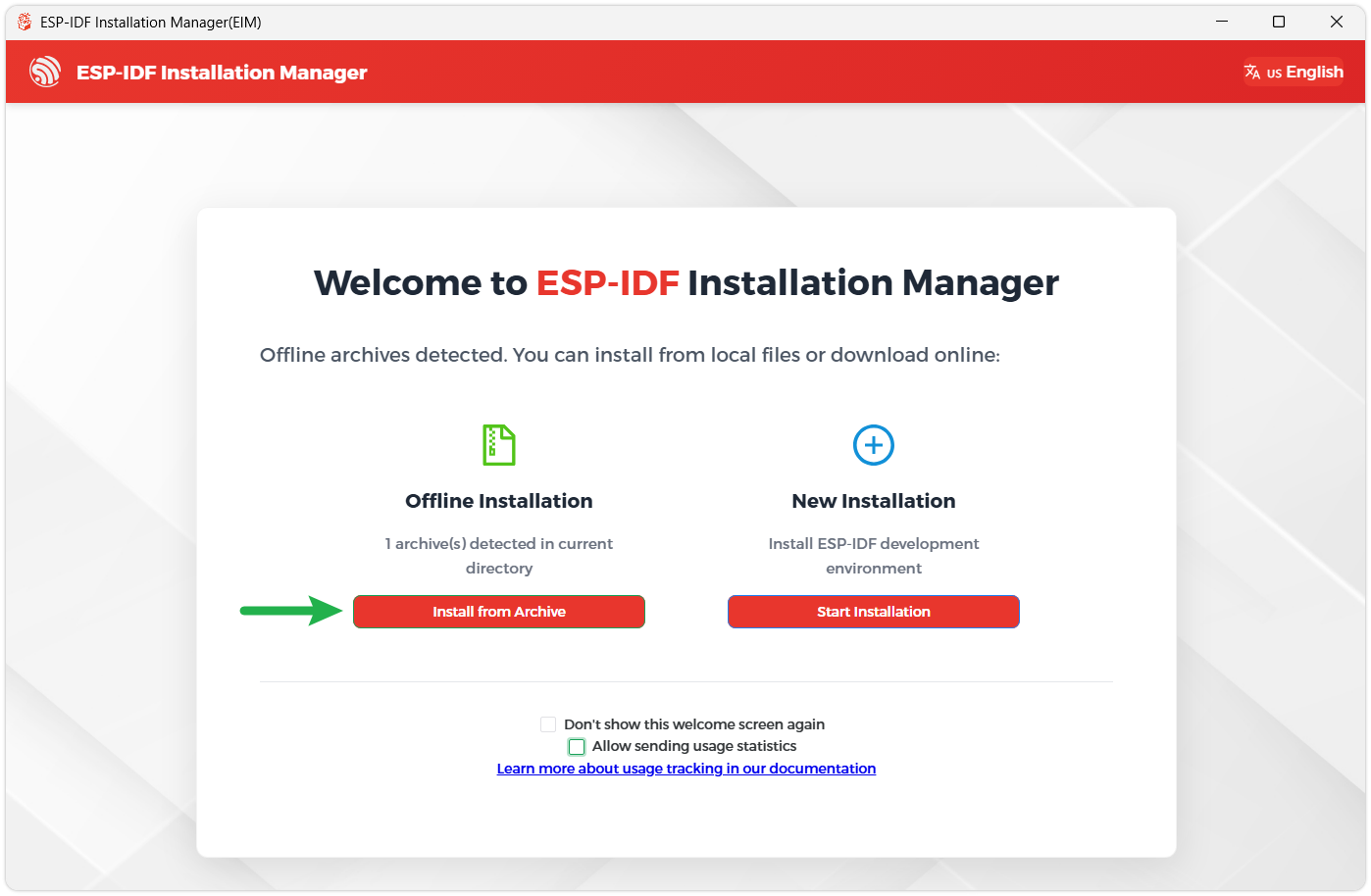
Once the download is complete, double-click to run the ESP-IDF Installer (eim-gui-windows-x64.exe).
The installer will automatically detect if the offline package exists in the same directory. Click Install from archive.
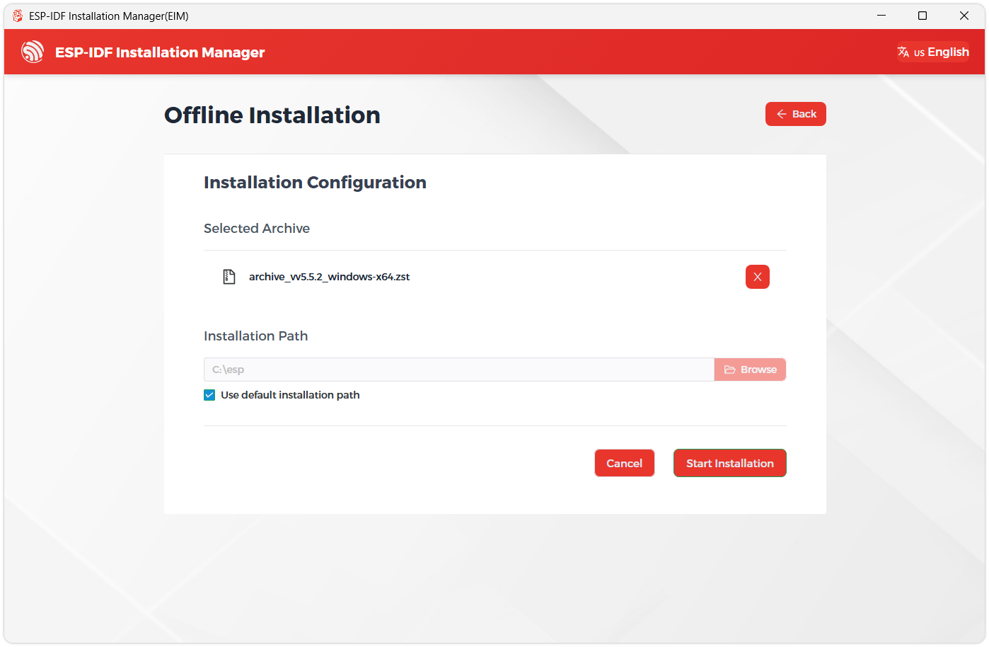
Next, select the installation path. We recommend using the default path. If you need to customize it, ensure the path does not contain Chinese characters or spaces. Click Start installation to proceed.
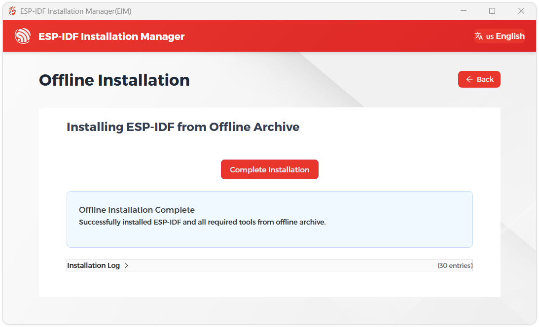
When you see the following screen, the ESP-IDF installation is successful.
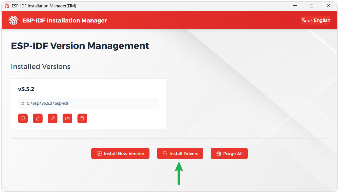
We recommend installing the drivers as well. Click Finish installation, then select Install driver.
Install Visual Studio Code and the ESP-IDF Extension
Download and install Visual Studio Code.
During installation, it is recommended to check Add "Open with Code" action to Windows Explorer file context menu to facilitate opening project folders quickly.
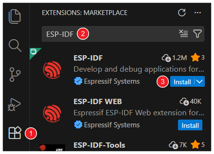
In VS Code, click the Extensions icon
 in the Activity Bar on the side (or use the shortcut Ctrl + Shift + X) to open the Extensions view.
Enter ESP-IDF in the search box, locate the ESP-IDF extension, and click Install.
For ESP-IDF extension versions ≥ 2.0, the extension will automatically detect and recognize the ESP-IDF environment installed in the previous steps, requiring no manual configuration.
Example
The ESP-IDF examples are located in the ESP-IDF directory of the example package.
| Example | Basic Program Description | Dependency Library |
|---|---|---|
| 01_Factory | Comprehensive test program | - |
| 02_SD | Test TF card read/write | - |
| 03_Brightness | LVGL example program | - |
| 04_LVGL | Run LVGL benchmark example | - |
01_Factory
Example Description
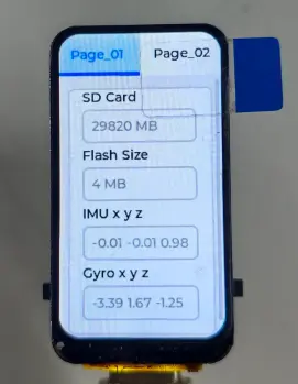
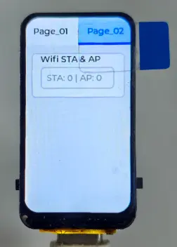
- This example tests the functions of the onboard modules of the ESP32-C3-LCD-1.47. The screen will display information about each module, and the user can switch pages by pressing the BOOT button.
Hardware Connection
- Connect the board to the computer.
- Insert the TF card into the card slot.
Code Analysis
IO_EXTENSION_Init(): Initializes I/O expansion (such as backlight/button control pins).LCD_Init(): Initializes the LCD screen and display interface.SD_Init()/QMI8658_Init()/Wireless_Init(): Initializes the TF card, IMU, wireless, and other onboard modules for comprehensive function demonstration.lvgl_display_init()/Lvgl_Example1(): Initializes the LVGL display and starts the example UI page.while (true) { lv_timer_handler(); ... }: In the task loop, periodically drives LVGL and sensor polling to keep the interface and data refreshed.void Factory_Example(void){ESP_LOGI(TAG, "board init");IO_EXTENSION_Init();ESP_ERROR_CHECK(LCD_Init());SD_Init();QMI8658_Init();Wireless_Init();ESP_LOGI(TAG, "lvgl init");lvgl_display_init();Lvgl_Example1();while (true) {lv_timer_handler();vTaskDelay(pdMS_TO_TICKS(10));QMI8658_Loop();}}
Operation Result
- After flashing, the image is displayed on the screen.
02_SD
Example Description
- This example demonstrates the ESP32-C3-LCD-1.47 reading a JPG image from the TF card and displaying it on the screen.
Hardware Connection
- Connect the board to the computer.
- Insert the TF card into the card slot (the TF card needs to be formatted as FAT32).
- Place the image
image_01.jpgin the root directory of the TF card.
Code Analysis
ESP_GOTO_ON_ERROR(..., EXIT, ...): Serial initialization/check process; any failure jumps directly to a unified exit path, reducing nested checks.jpg_decode_buffer_init(): Initializes the global buffer required for JPEG decoding.sd_init_with_retry()/sd_find_jpg()/sd_read_file_retry(): TF card initialization, JPG file search, and file read (with retries) to improve reliability.lcd_draw_jpg(jpg_data, jpg_size): Decodes the read JPG data and draws it on the screen.EXIT: free(jpg_data): Frees the dynamically allocated image buffer, then enters awhile (true)loop to keep the task alive for observation.void SD_Example(void){esp_err_t ret = ESP_OK;char jpg_path[SD_EXAMPLE_PATH_MAX] = {0};uint8_t *jpg_data = NULL;size_t jpg_size = 0;ESP_GOTO_ON_ERROR(IO_EXTENSION_Init(), EXIT, TAG, "IO init failed");ESP_GOTO_ON_ERROR(LCD_Init(), EXIT, TAG, "LCD init failed");ESP_GOTO_ON_ERROR(jpg_decode_buffer_init(), EXIT, TAG, "alloc global jpg buffer failed");ESP_GOTO_ON_ERROR(sd_init_with_retry(), EXIT, TAG, "SD init failed");ESP_GOTO_ON_ERROR(sd_find_jpg(jpg_path, sizeof(jpg_path)), EXIT, TAG, "jpg not found");ESP_GOTO_ON_ERROR(sd_read_file_retry(jpg_path, &jpg_data, &jpg_size), EXIT, TAG, "read jpg failed");ESP_GOTO_ON_ERROR(lcd_draw_jpg(jpg_data, jpg_size), EXIT, TAG, "draw jpg failed");EXIT:free(jpg_data);while (true) {vTaskDelay(pdMS_TO_TICKS(1000));}}
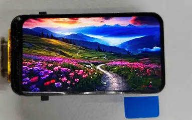
Operation Result
After flashing, the image is displayed on the screen.
03_Brightness
Example Description
- This example demonstrates controlling the screen brightness using the BOOT button. Double‑clicking the BOOT button switches the control logic.
Hardware Connection
- Connect the board to the computer.
Code Analysis
IO_EXTENSION_Init()/LCD_Init(): Initializes I/O expansion and LCD display, providing the underlying driver for LVGL display.lvgl_display_init(): Registers the display driver and buffer, allowing LVGL to refresh the screen normally.boot_key_init()/boot_key_poll(): Initializes and polls the BOOT button for switching brightness adjustment logic / triggering events.ui_init(): Initializes the UI elements (text, progress bar, etc.) for the brightness control example.while (true) { ... lv_timer_handler(); ... }: Loops to drive the button and LVGL task scheduling, achieving real‑time UI updates.void Brightness_Example(void){ESP_ERROR_CHECK(IO_EXTENSION_Init());ESP_ERROR_CHECK(LCD_Init());lvgl_display_init();boot_key_init();ui_init();while (true) {boot_key_poll();lv_timer_handler();vTaskDelay(pdMS_TO_TICKS(10));}}
Operation Result
04_LVGL
Example Description
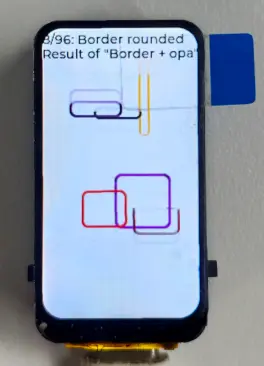
- This example demonstrates the ESP32-C3-LCD-1.47 running the LVGL benchmark example.
void LVGL_Benchmark_Example(void)
{
    ESP_ERROR_CHECK(IO_EXTENSION_Init());
    ESP_ERROR_CHECK(LCD_Init());
    lvgl_display_init();
    xTaskCreate(lvgl_benchmark_task, "lvgl_bench", 6144, NULL, 5, NULL);
}
Code Analysis
IO_EXTENSION_Init()/LCD_Init(): Initializes the board‑level I/O and LCD display interface.lvgl_display_init(): Initializes the LVGL display layer so the benchmark can output to the screen.xTaskCreate(lvgl_benchmark_task, ...): Creates a benchmark task to avoid blocking in the initialization function; the benchmark logic executes in a separate task and refreshes the interface.
Operation Result
Resources
1. Hardware Resources
Development Board Design Files
2. Example
3. Technical Manuals
ESP32-C3 Chip Official Manuals
Support
Monday-Friday (9:30-6:30) Saturday (9:30-5:30)
Email: services01@spotpear.com
[Tutorial Navigation]
- Features
- Specifications
- Interface Introduction
- Dimensions
- Working with Arduino
- Arduino Getting Started
- Setting Up the Development Environment
- 1. Installing and Configuring the Arduino IDE
- 2. Installing Libraries
- 3. Arduino Project Parameter Settings
- Example
- ESP-IDF
- Resources
- Support