


- sales/support
Google Chat:---
- sales
+86-0755-88291180
- sales01
sales@spotpear.com
- sales02
dragon_manager@163.com
- support
tech-support@spotpear.com
- CEO-Complaints
zhoujie@spotpear.com
- Only Tech-Support
WhatsApp:13246739196
- Purchase/Shipping/Refund
WhatsApp:13424403025
- HOME
- >
- ARTICLES
- >
- Common Moudle
- >
- ESP
ESP32-S3-ePaper-13.3E6 User Guide
Features
Driver Board Features
- Powered by the ESP32-S3-WROOM-2-N32R16V module, featuring an Xtensa 32-bit LX7 dual-core processor with a main frequency of up to 240MHz
- Integrated 512 KB SRAM, 384 KB ROM, 16 MB PSRAM, and 32 MB Flash
- Integrated 2.4GHz Wi-Fi and Bluetooth LE dual-mode wireless communication with excellent RF performance
- USB Type-C interface, eliminating concerns about plug orientation
- Onboard CH343 and CH334 chips, enabling both USB and UART development via a single Type‑C port
- Onboard 13.3E6 e‑Paper interface, supporting direct connection to the 13.3E6 full‑color e‑Paper screen
- Onboard audio codec chip supports voice capture and playback, facilitating AI voice interaction applications
- Onboard efficient charge/discharge management chip ETA6098 and MX1.25 lithium battery connector
- Built-in TF card slot, supports external storage of images or files
e‑Paper Features
- E Ink Spectra 6 (E6) technology, delivering high‑contrast, high‑saturation color display
- No backlight required; can retain the last displayed content for a long time after power-off
- Very low power consumption, mainly only consumes power during refresh
Onboard Resources
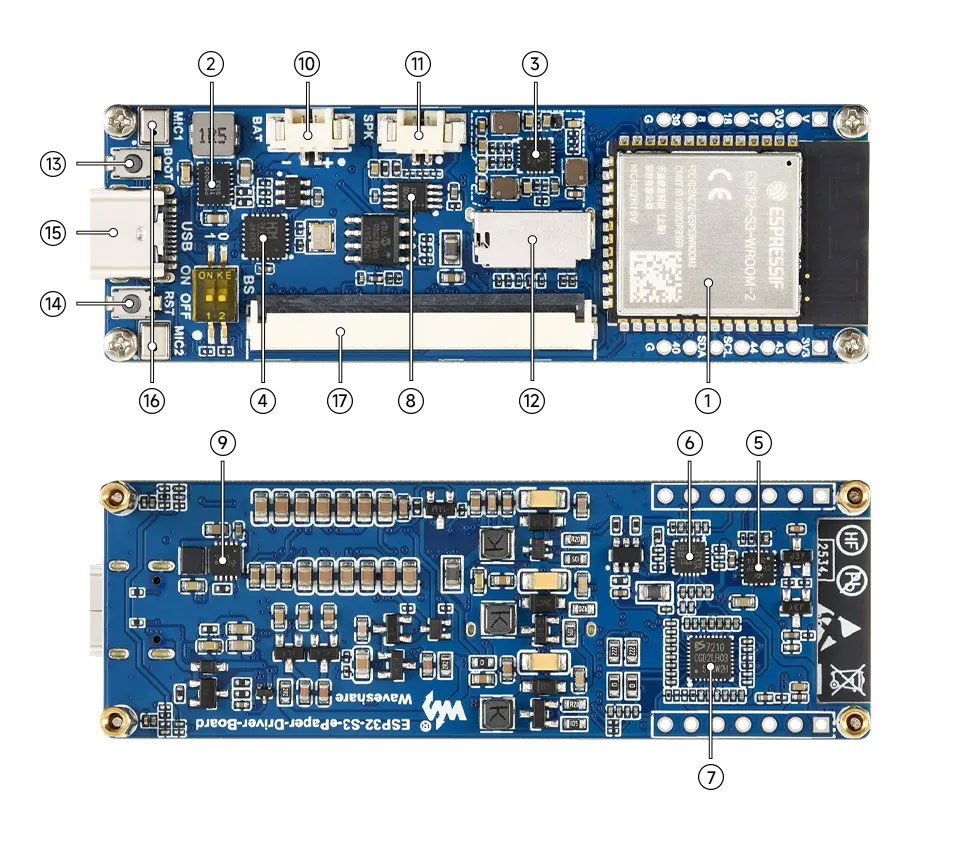
- ESP32-S3-WROOM-1-N16R8 Wi-Fi and Bluetooth SoC, up to 240MHz operating frequency, stacked with 16MB Flash and 8MB PSRAM
- TPS63020DSJR DC/DC boost converter
- EA3036CQBR Power management IC
- USB HUB Chip
- USB‑to‑UART Chip
- ES8311 DAC Audio Codec High-performance, low-power audio digital-to-analog converter
- ES7210 ADC Audio Codec High-performance, low-power audio analog-to-digital converter, supports multi-microphone input
- NS4150B Audio power amplifier chip
- ETA6098 Battery charge/discharge management chip
- MX1.25 2PIN Lithium Battery Header For connecting a lithium battery
- MX1.25 2PIN Speaker Header Audio signal output, for connecting external speaker
- TF Card Slot TF card must be formatted as FAT32 for use
- BOOT Button Press and hold the BOOT button to power on again to enter download mode
- Reset Button
- Type-C Interface ESP32-S3 USB interface for program flashing and serial logging
- Microphone For audio capture
- e‑Paper Driver Interface
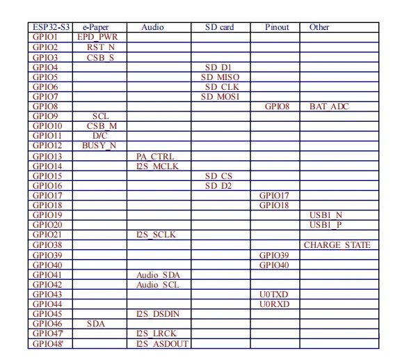
Interface Introduction
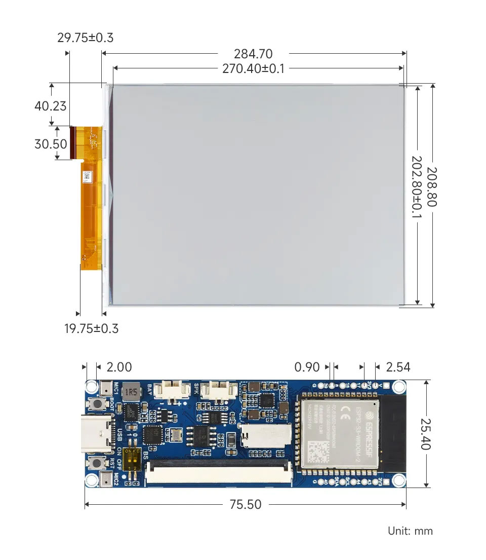
Dimensions
orking with Arduino
This chapter contains the following sections. Please read as needed:
Arduino Getting Started
New to Arduino ESP32 development and looking for a quick start? We have prepared a comprehensive Getting Started Tutorial for you.
- Section 0: Getting to Know ESP32
- Section 1: Installing and Configuring Arduino IDE
- Section 2: Arduino Basics
- Section 3: Digital Output/Input
- Section 4: Analog Input
- Section 5: Pulse Width Modulation (PWM)
- Section 6: Serial Communication (UART)
- Section 7: I2C Communication
- Section 8: SPI Communication
- Section 9: Wi-Fi Basics
- Section 10: Web Server
- Section 11: Bluetooth
- Section 12: LVGL GUI Development
- Section 13: Comprehensive Project
Note: This tutorial uses the ESP32-S3-Zero as a reference example, and all hardware code is based on its pinout. Before you start, we recommend checking the pinout of your development board to ensure the pin configuration is correct.
Setting Up Development Environment
1. Installing and Configuring Arduino IDE
Please refer to the tutorial Installing and Configuring Arduino IDE to download and install the Arduino IDE and add ESP32 support.
Board Installation Instructions for ESP32-S3-ePaper-13.3E6
| Board Name | Installation Requirement | Version Requirement |
|---|---|---|
| ESP32 by Espressif Systems | "Install Offline" / "Install Online" | 3.2.0 |
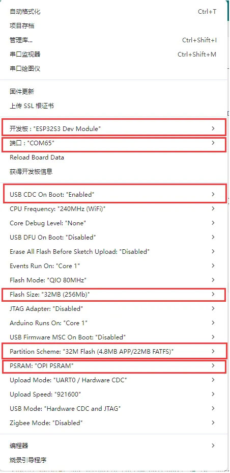
2. Arduino Project Parameter Settings
Demo
The Arduino demos are located in the Arduino/examples directory of the demo package.
| Demo | Basic Program Description | Dependency Library |
|---|---|---|
| 01_ADC_Test | Get the voltage value of the lithium battery | - |
| 02_Audio_out | Audio playback example | - |
| 03_E-Paper_Example | 13.3inch e-Paper E6 e‑paper screen example program | - |
| 04_SD_Test | Read TF card and display images | - |
| 05_Loader_esp32wf | WiFi image transfer example | - |
01_ADC_Test
Demo Description
- The analog voltage connected through the GPIO is converted to digital by the ADC, and then the actual lithium battery voltage is calculated and printed to the terminal.
Hardware Connection
- Connect the board to the computer using a USB cable
Code Analysis
adc_bsp_init(void): Initializes ADC1, including creating an ADC one-shot trigger unit and configuring Channel 7 of ADC1.adc_get_value(float *value,int *data): Reads the value from Channel 7 of ADC1, calculates the corresponding voltage based on the reference voltage and resolution, and stores it at the location pointed to by the passed pointer. Stores 0 if the read fails.adc_example(void* parameter): After initializing ADC1, creates an ADC task. This task reads the ADC value every second and calculates the system voltage from the raw ADC reading.
Operation Result
- After the program is compiled and downloaded, you can view the printed ADC values and voltage output by opening the Serial Monitor, as shown in the following image:

02_Audio_out
Demo Description
- This example drives the ES8311 audio codec to play music.
Hardware Connection
- Connect the board to the computer using a USB cable
Code Analysis
Configure and initialize the ES8311 audio codec.
void setup() {Serial.begin(115200);Wire.begin(I2C_SDA, I2C_SCL);pinMode(PA_CTRL, OUTPUT);digitalWrite(PA_CTRL, HIGH);es8311_codec_init();setupI2S();Serial.println("I2S Initialized");}Continuously write built-in audio data to the I2S bus for looped playback.
i2s.write((uint8_t *)audio_data, AUDIO_SAMPLES * 2);
Operation Result
- The device will play the auido directly without showing content on the screen
03_E-Paper_Example
Demo Description
- This is a local Arduino example for the 13.3inch E6 e-Paper screen. It performs e‑Paper initialization, clears the screen, displays images, and draws basic graphics and text.
Hardware Connection
- Connect the board to the computer using a USB cable
Code Analysis
Display a predefined image.
#if 1 // show bmpprintf("show bmp1-----------------\r\n");EPD_13IN3E_Display(Image6color);DEV_Delay_ms(3000);#endifDraw basic shapes, Chinese/English text, numbers, and refresh the display.
#if 1 // Drawing on the imagePaint_NewImage(Image, EPD_13IN3E_WIDTH, EPD_13IN3E_HEIGHT, 90, EPD_13IN3E_WHITE);Paint_SetScale(6);//1.Select Imageprintf("SelectImage:Image\r\n");Paint_SelectImage(Image);Paint_Clear(EPD_13IN3E_WHITE);// 2.Drawing on the imageprintf("Drawing:Image\r\n");Paint_DrawPoint(10, 80, EPD_13IN3E_RED, DOT_PIXEL_1X1, DOT_STYLE_DFT);Paint_DrawPoint(10, 90, EPD_13IN3E_BLUE, DOT_PIXEL_2X2, DOT_STYLE_DFT);Paint_DrawPoint(10, 100, EPD_13IN3E_GREEN, DOT_PIXEL_3X3, DOT_STYLE_DFT);Paint_DrawLine(20, 70, 70, 120, EPD_13IN3E_YELLOW, DOT_PIXEL_1X1, LINE_STYLE_SOLID);Paint_DrawLine(70, 70, 20, 120, EPD_13IN3E_YELLOW, DOT_PIXEL_1X1, LINE_STYLE_SOLID);Paint_DrawRectangle(20, 70, 70, 120, EPD_13IN3E_BLACK, DOT_PIXEL_1X1, DRAW_FILL_EMPTY);Paint_DrawRectangle(80, 70, 130, 120, EPD_13IN3E_BLACK, DOT_PIXEL_1X1, DRAW_FILL_FULL);Paint_DrawCircle(45, 95, 20, EPD_13IN3E_BLACK, DOT_PIXEL_1X1, DRAW_FILL_EMPTY);Paint_DrawCircle(105, 95, 20, EPD_13IN3E_WHITE, DOT_PIXEL_1X1, DRAW_FILL_FULL);Paint_DrawLine(85, 95, 125, 95, EPD_13IN3E_YELLOW, DOT_PIXEL_1X1, LINE_STYLE_DOTTED);Paint_DrawLine(105, 75, 105, 115, EPD_13IN3E_YELLOW, DOT_PIXEL_1X1, LINE_STYLE_DOTTED);Paint_DrawString_CN(10, 130, "你好 abc", &Font12CN, EPD_13IN3E_BLACK, EPD_13IN3E_WHITE);Paint_DrawString_CN(10, 150, "微雪电子", &Font24CN, EPD_13IN3E_WHITE, EPD_13IN3E_BLACK);Paint_DrawNum(10, 33, 123456789, &Font12, EPD_13IN3E_BLACK, EPD_13IN3E_WHITE);Paint_DrawNum(10, 50, 987654321, &Font16, EPD_13IN3E_WHITE, EPD_13IN3E_BLACK);Paint_DrawString_EN(145, 0, "Waveshare", &Font16, EPD_13IN3E_BLACK, EPD_13IN3E_WHITE);Paint_DrawString_EN(145, 35, "Waveshare", &Font16, EPD_13IN3E_GREEN, EPD_13IN3E_WHITE);Paint_DrawString_EN(145, 70, "Waveshare", &Font16, EPD_13IN3E_BLUE, EPD_13IN3E_WHITE);Paint_DrawString_EN(145, 105, "Waveshare", &Font16, EPD_13IN3E_RED, EPD_13IN3E_WHITE);Paint_DrawString_EN(145, 140, "Waveshare", &Font16, EPD_13IN3E_YELLOW, EPD_13IN3E_WHITE);printf("EPD_Display\r\n");EPD_13IN3E_Display(Image);DEV_Delay_ms(3000);#endif
Operation Result
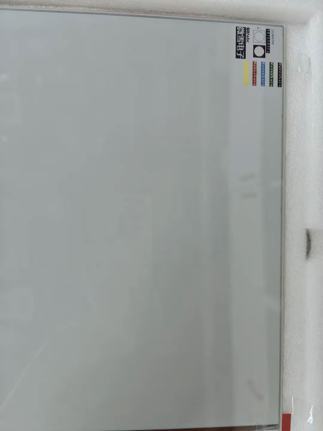
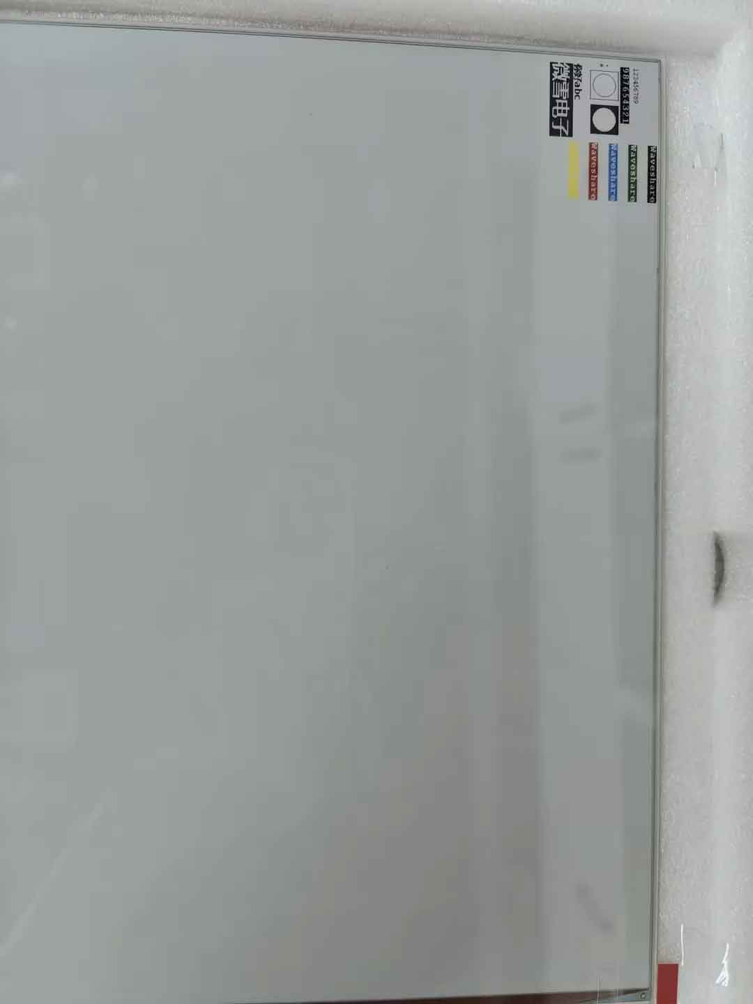
- The screen refreshes, clears, displays an image, and draws basic graphics and text.

04_SD_Test
Demo Description
- This example reads BMP images from a TF card and refreshes them on the e-Paper display.
Hardware Connection
- Connect the board to the computer using a USB cable
- Insert the TF card module with a TF card containing a bmp folder with images in the root directory.
Code Analysis
Configure and mount the TF card.
//sdcard initSerial.begin(115200);delay(1000);SD_MMC.setPins(SD_CLK, SD_CMD, SD_D0, SD_D1, SD_D2, SD_D3);if (!SD_MMC.begin( "/sdcard", true)) {printf("TF card failed to mount\r\n");return;}printf("TF card success to mount\r\n");Read .bmp images from the bmp folder on the TF card.
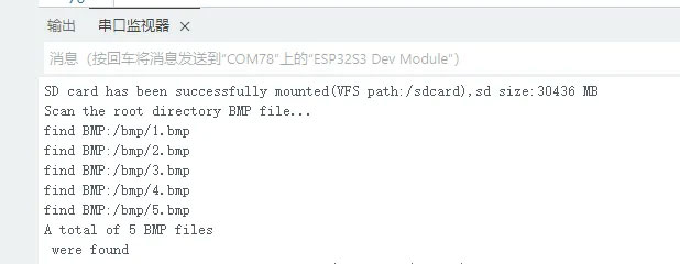
Serial.println("Scan the root directory BMP file...");File rootDir = SD_MMC.open("/bmp");if (rootDir && rootDir.isDirectory()) {File file = rootDir.openNextFile();while (file && bmpFileCount < 32) {if (!file.isDirectory()) {String fileName = file.name();String fullPath = file.path();fileName.toLowerCase();if (fileName.endsWith(".bmp")) {bmpFilePaths[bmpFileCount++] = MOUNT_POINT + fullPath;Serial.printf("find BMP:%s\n", fullPath.c_str());}}file.close();file = rootDir.openNextFile();}rootDir.close();}else{Serial.println("error : failed to open the root directory!");}
Operation Result
- Serial port prints TF card information.
- Reads and displays images from the TF card.

05_Loader_esp32wf
Demo Description
- WiFi demoWARNING
This module only supports the 2.4GHz network band.
Hardware Connection
- Connect the board to the computer using a USB cable
Code Modification
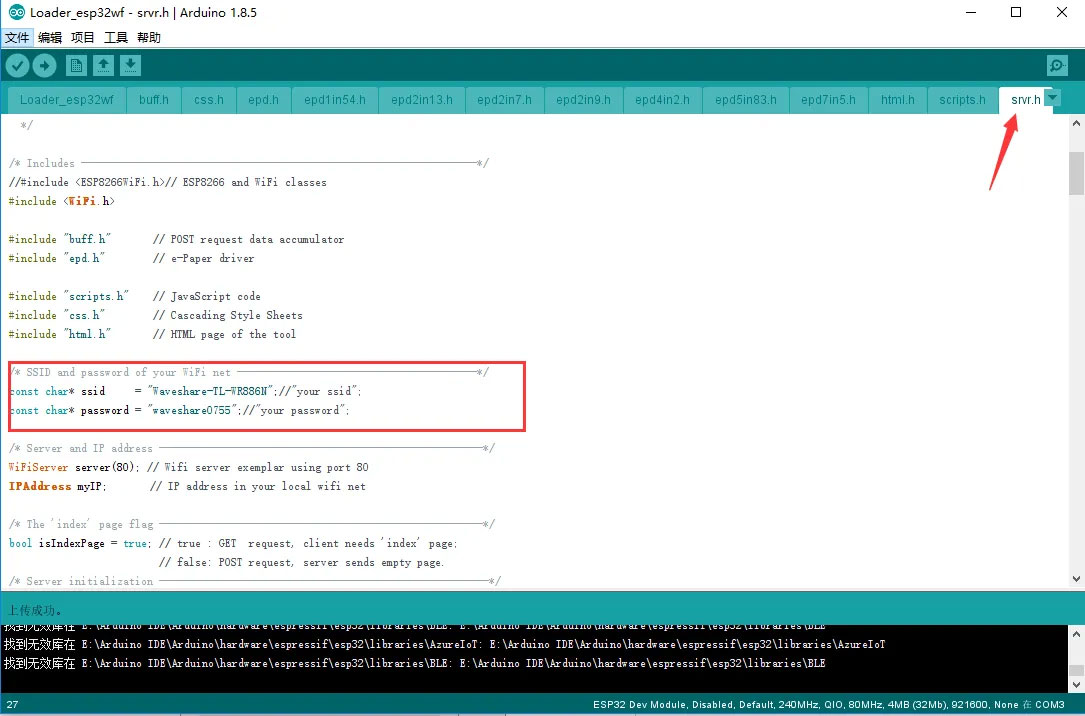
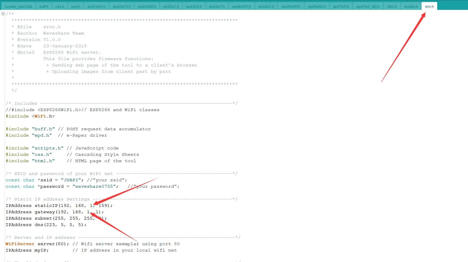
Open the
srvr.hfile and change thessidandpasswordto the actual WiFi username and password being used.INFOModify the Wi-Fi username and password at this location to your own router's or mobile hotspot's Wi-Fi credentials. In this program, the ESP32 acts as a client (slave), not an access point; it does not broadcast its own Wi-Fi hotspot.
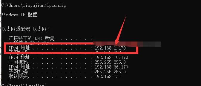
Press
Win + R, typeCMD, and open the command prompt to obtain the computer's IP address.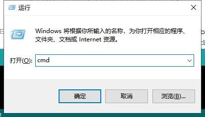
Open the
srvr.h fileand modify the network segment shown in the image to match your network segment.WARNINGThe ESP32's IP address (the last octet) must be different from the computer's IP address, but the other three octets must be exactly the same.
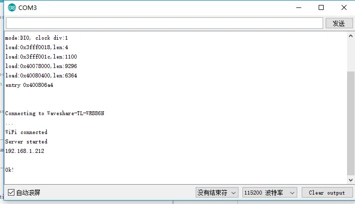
Then click Upload to compile and download the program to the ESP32 driver board.
Open the Serial Monitor, set the baud rate to 115200, and you will see the ESP32's IP address printed:
On a computer or mobile phone (ensure the device is connected to the same WiFi network as the ESP32), open a browser, enter the ESP32's IP address in the address bar, and open it. The operation interface will appear as shown below:
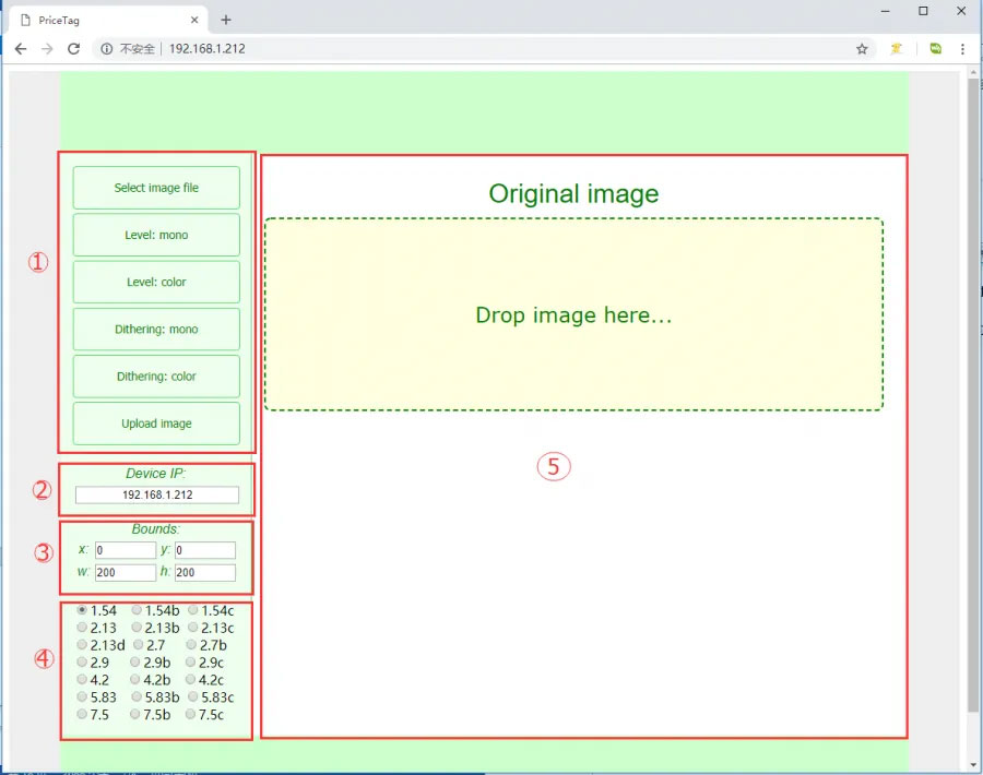
The interface is divided into five areas: Image Operation Area:
Select Image file: Click to select an image from the computer or phoneLevel: mono: Black‑and‑white color‑level image processing algorithmLevel: color: Multi‑color color‑level image processing algorithm (effective only for multi‑color screens)Dithering: mono: Black‑and‑white dithering image processing algorithmDithering: color: Multi‑color dithering image processing algorithm (effective only for multi‑color screens)Update image: Upload the image- IP Information Display Area: Shows the IP address of the currently connected module
- Image Size Setting Area: Here x and y set the starting position for display, relative to the selected image file. For example, if you select an 800x480 image but the connected e‑Paper screen is 2.9 inches, the screen cannot display the whole image. The algorithm automatically crops a portion starting from the top‑left corner. Setting x and y allows you to customize the starting crop position. w and h are the resolution of the current e‑Paper screen. W and h represent the resolution of the current e-Paper screen.
WARNINGIf you change the x and y values, you need to click the processing algorithm button again to regenerate the image.
- Model Selection Area: Here you can select the model of the connected e‑Paper screen
- Image Display Area: Shows the selected image and the processed result
INFOWhile uploading an image, the progress will be shown at the bottom.
In area ①, click
Select image fileto choose an image, or simply drag and drop an image into theOriginal imagearea.In area ④, select the corresponding e‑Paper screen model, e.g.,
13.3EIn area ①, click an image processing algorithm, e.g.,
Dithering: colorIn area ①, click
Upload imageto upload the image and display it on the e‑paper screen.
ESP-IDF
This chapter contains the following sections. Please read as needed:
ESP-IDF Getting Started
New to ESP32 ESP-IDF development and looking to get started quickly? We have prepared a general Getting Started Tutorial for you.
- Section 1: Environment Setup
- Section 2: Running Examples
- Section 3: Creating a Project
- Section 4: Using Components
- Section 5: Debugging
- Section 6: FreeRTOS
- Section 7: Peripherals
- Section 8: Wi-Fi Programming
- Section 9: BLE Programming
Please Note: This tutorial uses the ESP32-S3-Zero as a teaching example, and all hardware code is based on its pinout. Before you start, it is recommended that you check the pinout of your development board to ensure the pin configuration is correct.
Setting Up Development Environment
For the ESP32-S3-ePaper-Driver-Board development board, ESP-IDF version V5.5.0 or above is required.
The following guide uses Windows as an example, demonstrating development using VS Code + the ESP-IDF extension. macOS and Linux users should refer to the official documentation.
Install the ESP-IDF Development Environment
Download the installation manager from the ESP-IDF Installation Manager page. This is Espressif's latest cross-platform installer. The following steps demonstrate how to use its offline installation feature.
Click the Offline Installer tab on the page, then select Windows as the operating system and choose your desired version from the filter bar.
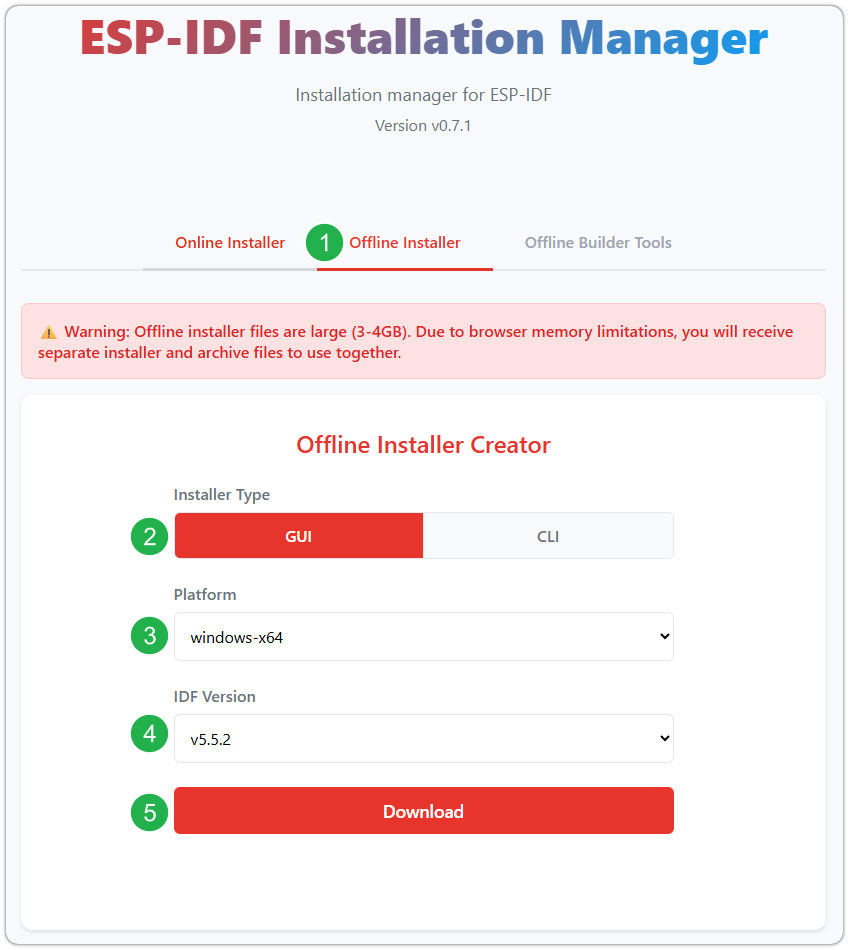
After confirming your selection, click the download button. The browser will automatically download two files: the ESP-IDF Offline Package (.zst) and the ESP-IDF Installer (.exe).
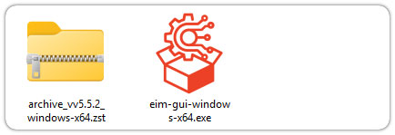
Please wait for both files to finish downloading.
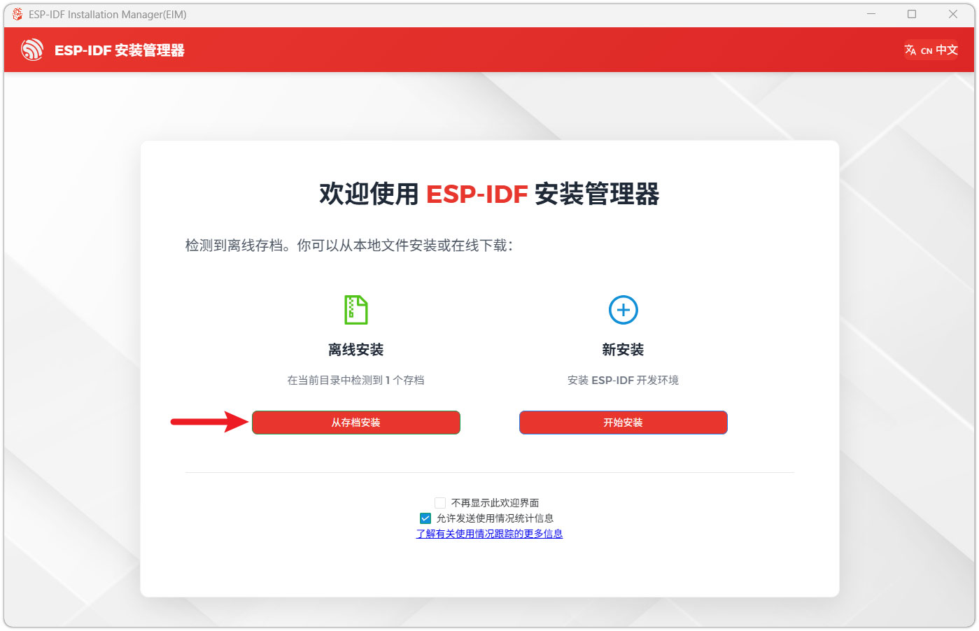
Once the download is complete, double-click to run the ESP-IDF Installer (eim-gui-windows-x64.exe).
The installer will automatically detect if the offline package exists in the same directory. Click Install from archive.
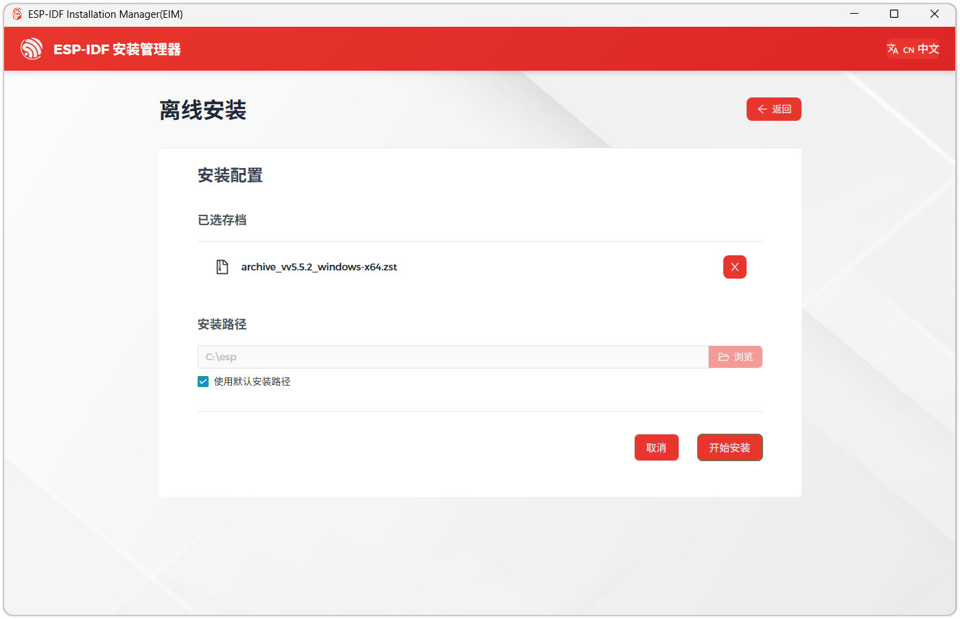
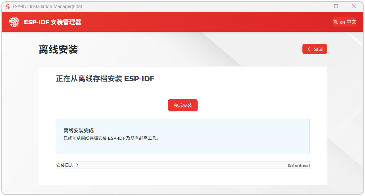
Next, select the installation path. We recommend using the default path. If you need to customize it, ensure the path does not contain Chinese characters or spaces. Click Start installation to proceed.
When you see the following screen, the ESP-IDF installation is successful.
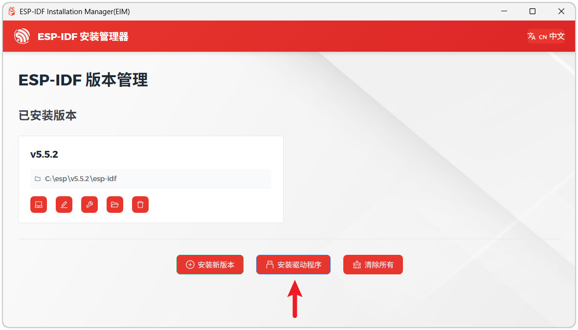
We recommend installing the drivers as well. Click Finish installation, then select Install driver.
Install Visual Studio Code and the ESP-IDF Extension
Download and install Visual Studio Code.
During installation, it is recommended to check Add "Open with Code" action to Windows Explorer file context menu to facilitate opening project folders quickly.
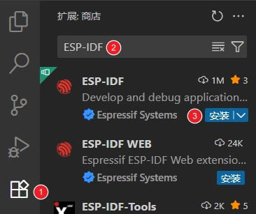
In VS Code, click the Extensions icon
 in the Activity Bar on the side (or use the shortcut Ctrl + Shift + X) to open the Extensions view.
Enter ESP-IDF in the search box, locate the ESP-IDF extension, and click Install.
For ESP-IDF extension versions ≥ 2.0, the extension will automatically detect and recognize the ESP-IDF environment installed in the previous steps, requiring no manual configuration.
Demo
The ESP-IDF demos are located in the ESP-IDF directory of the demo package.
| Demo | Basic Description |
|---|---|
| 01_ADC_Test | Get the lithium battery voltage value |
| 02_Mic_test | Play microphone recording through the speaker |
| 03_Music | Mount TF card and read/play music files from it |
| 04_E-Paper_Example | e‑Paper example program |
| 05_SD_Test | Read TF card and display images |
| 06_xiaozhi-esp32 | Xiaozhi AI application |
01_ADC_Test
Demo Description
- The analog voltage connected through the GPIO is converted to digital by the ADC, and then the actual lithium battery voltage is calculated and printed to the terminal.
Hardware Connection
- Connect the board to the computer using a USB cable
Code Analysis
adc_bsp_init(void): Initializes ADC1, including creating an ADC one-shot trigger unit and configuring Channel 7 of ADC1.adc_get_value(float *value,int *data): Reads the value from Channel 7 of ADC1, calculates the corresponding voltage based on the reference voltage and resolution, and stores it at the location pointed to by the passed pointer. Stores 0 if the read fails.adc_example(void* parameter): After initializing ADC1, creates an ADC task. This task reads the ADC value every second and calculates the system voltage from the raw ADC reading.
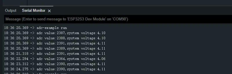
Operation Result
- After the program is compiled and downloaded, you can view the printed ADC values and voltage output by opening the Serial Monitor, as shown in the following image:
02_Mic_test
Demo Description
- Demonstrates how to get data from the microphone and then play it through the speaker
Hardware Connection
- Connect the development board to the computer
Code Analysis
i2c_master_Init();: Initializes the I2C bus.user_ui_init();: Initializes the global UI.user_button_init();: Initializes the audio interface.
Operation Result
The screen shows nothing.
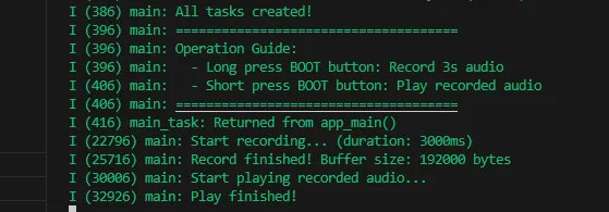
Long press the BOOT button to enter recording mode. Speak into the MIC, and it will automatically stop after 3 seconds.
Click the BOOT button to play the recorded sound. (If no recording exists, the played sound will be very harsh.)
Serial port prints:
03_Music
Demo Description
- Mounts a TF card and reads/plays audio files from it.
Hardware Connection
- Connect the development board to the computer
- Connect a speaker to the SPK interface.
Code Analysis
_sdcard_init();: Initializes the TF card and reads the audio files from it.i2c_master_init();: Initializes the I2C bus, providing a communication link for configuration command transmission to the ES8311 audio codec.audio_player_play(audio_fp);: Starts the audio player, reads the opened MP3 file, and drives the speaker through the ES8311 for playback.
Operation Result
- The screen shows nothing.
- The speaker plays audio.
04_E-Paper_Example
Demo Description
- This is a local ESP‑IDF example for the 13.3inch E6 e-Paper screen. It performs e‑Paper initialization, clears the screen, displays images, and draws basic graphics and text.
Hardware Connection
- Connect the development board to the computer
Code Analysis
Display a predefined image:
#if 1EPD_Display(Image6color);vTaskDelay(pdMS_TO_TICKS(3000));#endifDraw basic shapes, Chinese/English text, numbers, and refresh the display:
#if 1Paint_NewImage(Image_Mono, EPD_WIDTH, EPD_HEIGHT, 90, EPD_WHITE);Paint_SetScale(6);printf("SelectImage:Image\r\n");Paint_SelectImage(Image_Mono);Paint_Clear(EPD_WHITE);Paint_DrawPoint(10, 80, EPD_RED, DOT_PIXEL_1X1, DOT_STYLE_DFT);Paint_DrawPoint(10, 90, EPD_BLUE, DOT_PIXEL_2X2, DOT_STYLE_DFT);Paint_DrawPoint(10, 100, EPD_GREEN, DOT_PIXEL_3X3, DOT_STYLE_DFT);Paint_DrawLine(20, 70, 70, 120, EPD_YELLOW, DOT_PIXEL_1X1, LINE_STYLE_SOLID);Paint_DrawLine(70, 70, 20, 120, EPD_YELLOW, DOT_PIXEL_1X1, LINE_STYLE_SOLID);Paint_DrawRectangle(20, 70, 70, 120, EPD_BLACK, DOT_PIXEL_1X1, DRAW_FILL_EMPTY);Paint_DrawRectangle(80, 70, 130, 120, EPD_BLACK, DOT_PIXEL_1X1, DRAW_FILL_FULL);Paint_DrawCircle(45, 95, 20, EPD_BLACK, DOT_PIXEL_1X1, DRAW_FILL_EMPTY);Paint_DrawCircle(105, 95, 20, EPD_WHITE, DOT_PIXEL_1X1, DRAW_FILL_FULL);Paint_DrawLine(85, 95, 125, 95, EPD_YELLOW, DOT_PIXEL_1X1, LINE_STYLE_DOTTED);Paint_DrawLine(105, 75, 105, 115, EPD_YELLOW, DOT_PIXEL_1X1, LINE_STYLE_DOTTED);Paint_DrawString_CN(10, 130, "你好 abc", &Font16_UTF8, EPD_BLACK, EPD_WHITE);Paint_DrawString_CN(10, 170, "微雪电子", &Font16_UTF8, EPD_WHITE, EPD_BLACK);Paint_DrawNum(10, 10, 123456789, &Font12, EPD_BLACK, EPD_WHITE);Paint_DrawNum(10, 40, 987654321, &Font12, EPD_WHITE, EPD_BLACK);Paint_DrawString_EN(145, 0, "Waveshare", &Font16, EPD_BLACK, EPD_WHITE);Paint_DrawString_EN(145, 35, "Waveshare", &Font16, EPD_GREEN, EPD_WHITE);Paint_DrawString_EN(145, 70, "Waveshare", &Font16, EPD_BLUE, EPD_WHITE);Paint_DrawString_EN(145, 105, "Waveshare", &Font16, EPD_RED, EPD_WHITE);Paint_DrawString_EN(145, 140, "Waveshare", &Font16, EPD_YELLOW, EPD_WHITE);printf("EPD_Display\r\n");EPD_Display(Image_Mono);vTaskDelay(pdMS_TO_TICKS(3000));#endif
Operation Result
- The screen refreshes, clears, displays an image, and draws basic graphics and text.

05_SD_Test
Demo Description
- This example reads BMP images from a TF card and refreshes them on the e-Paper display.
Hardware Connection
- Connect the board to the computer using a USB cable
- Insert the TF card module with a TF card containing a bmp folder with images in the root directory.
Code Analysis
_sdcard_init: TF card initializationGUI_ReadBmp_RGB_6Color("/sdcard/bmp/13in3E.bmp", 0, 0);: Image decoding
Operation Result
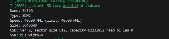
- Serial port prints TF card information.
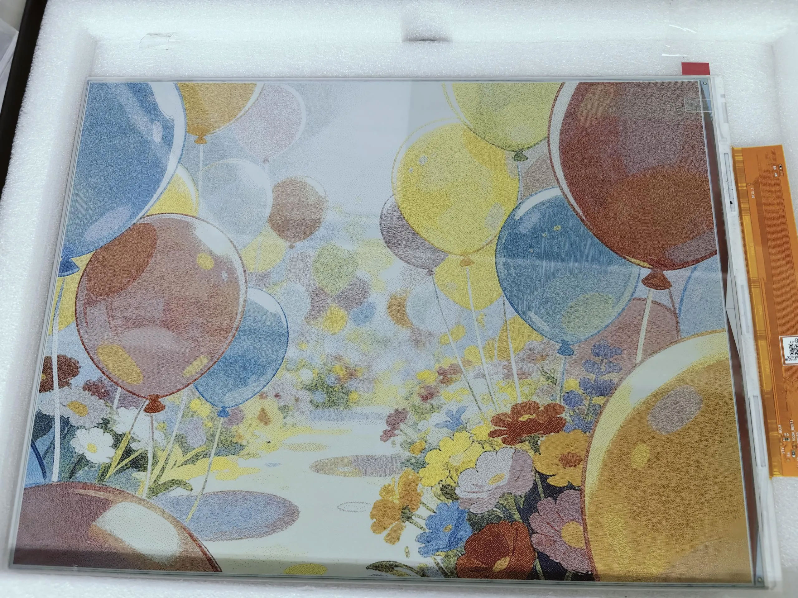
- Reads and displays images from the TF card.
06_xiaozhi-esp32
Hardware Connection
- Connect the board to the computer using a USB cable
- Copy all files from the TF card folder to sdcard, then insert the TF card module
Demo Description
- First download the Demo using your preferred method. After extracting, copy all files from the TF card directory to sdcard.
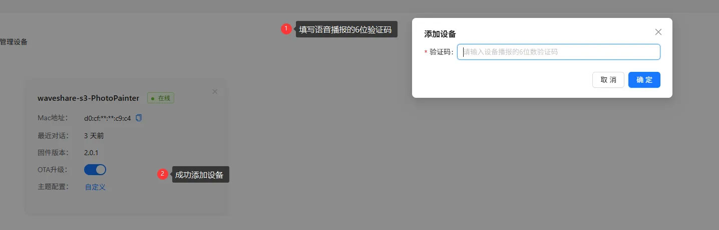
- The first boot will trigger a network configuration process. The voice will announce "Entering network configuration mode". At this point, use your phone to connect to
Xiaozhi-xxx(wherexxxis variable). - After successful network configuration, go to the Xiaozhi Console and add the corresponding device.
- Three working modes: Basic Mode (Mode 1), Local Server Mode (Mode 2), and AI Conversation Mode (Mode 3).
Mode 1
- The default mode is AI Conversation Mode (Mode 3). Press and hold the BOOT button to enter mode selection (the voice will announce it). Then press the BOOT button once to select Basic Mode (Mode 1). Press and hold the BOOT button again to enter this mode.
- Add photos you want to display to the
imgdirectory on the TF card. Only 24‑bit BMP images with resolutions of 1600x1200 or 1200x1600 are accepted. - Press the BOOT button once to display an image from the
imgdirectory. - Press the BOOT button to cycle through images.
Mode 2
- Press and hold the BOOT button to enter mode selection; press the BOOT button twice, then press and hold the BOOT button again to enter this mode.
- Use your phone or computer to connect to the Wi-Fi
esp_networkwith password1234567890. After successful connection, go to the image selection interface as shown: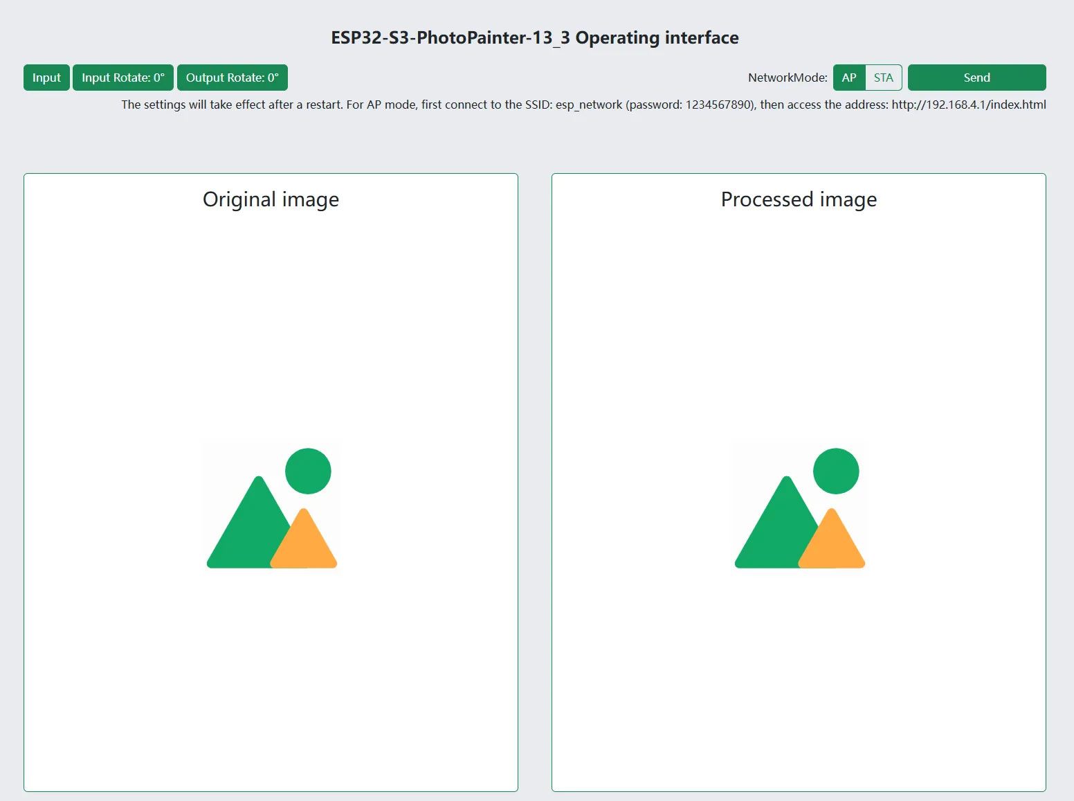
- On the web page, you can directly select, preview, and push images to the e‑paper display.
- For AP mode: first connect your phone or computer to the Wi-Fi with SSID
esp_network(password:1234567890), then visithttp://192.168.4.1/index.html. - For STA mode: first configure the network using Mode 3, then visit
http://esp32-s3-photopainter-13_3.local/index.html.
Mode 3
- Press and hold the BOOT button to enter mode selection; press the BOOT button three times, then press and hold the BOOT button again to enter this mode.
- After initialization is complete, wake up the device with the wake word "Hello, Xiaozhi".
- After waking up, you can converse normally.
- Through conversation, you can retrieve and display the number of images in the
imgdirectory on the TF card. - Regarding AI‑generated images: for example, you can say "Help me generate an image of the moon". To use this feature, you need to configure Volcanic Engine. Refer to Volcanic Engine Text‑to‑Image Configuration for details.
Volcanic Engine Text‑to‑Image Configuration
- Firstly, you need to obtain the access key, model name, and URL. Currently, a test model is being used, which will be discontinued later. Users need to configure their own models. The relevant code section and configuration in the
config.txtfile are shown below: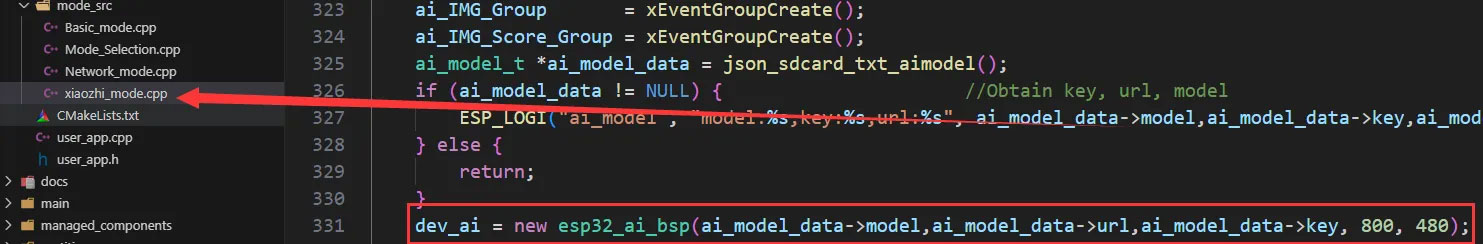

- Go to the Volcanic Engine Console
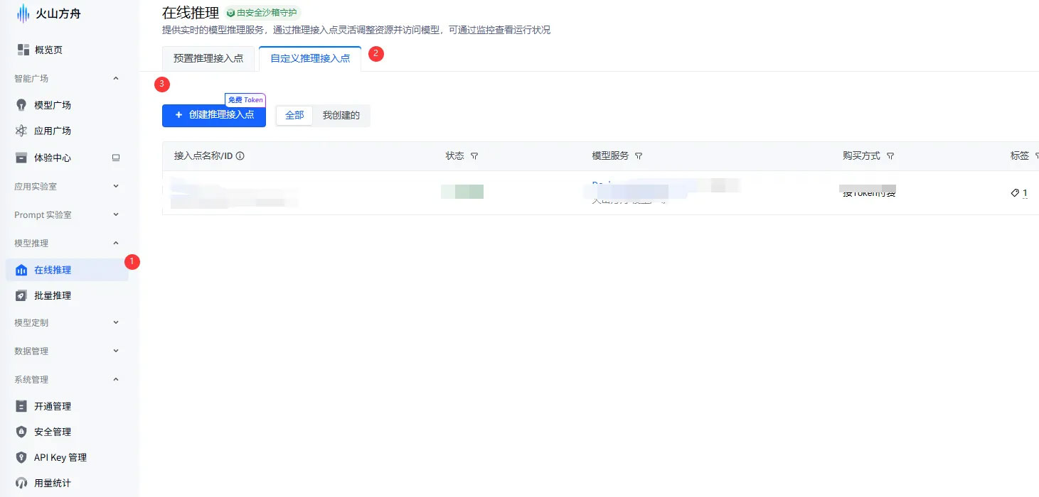
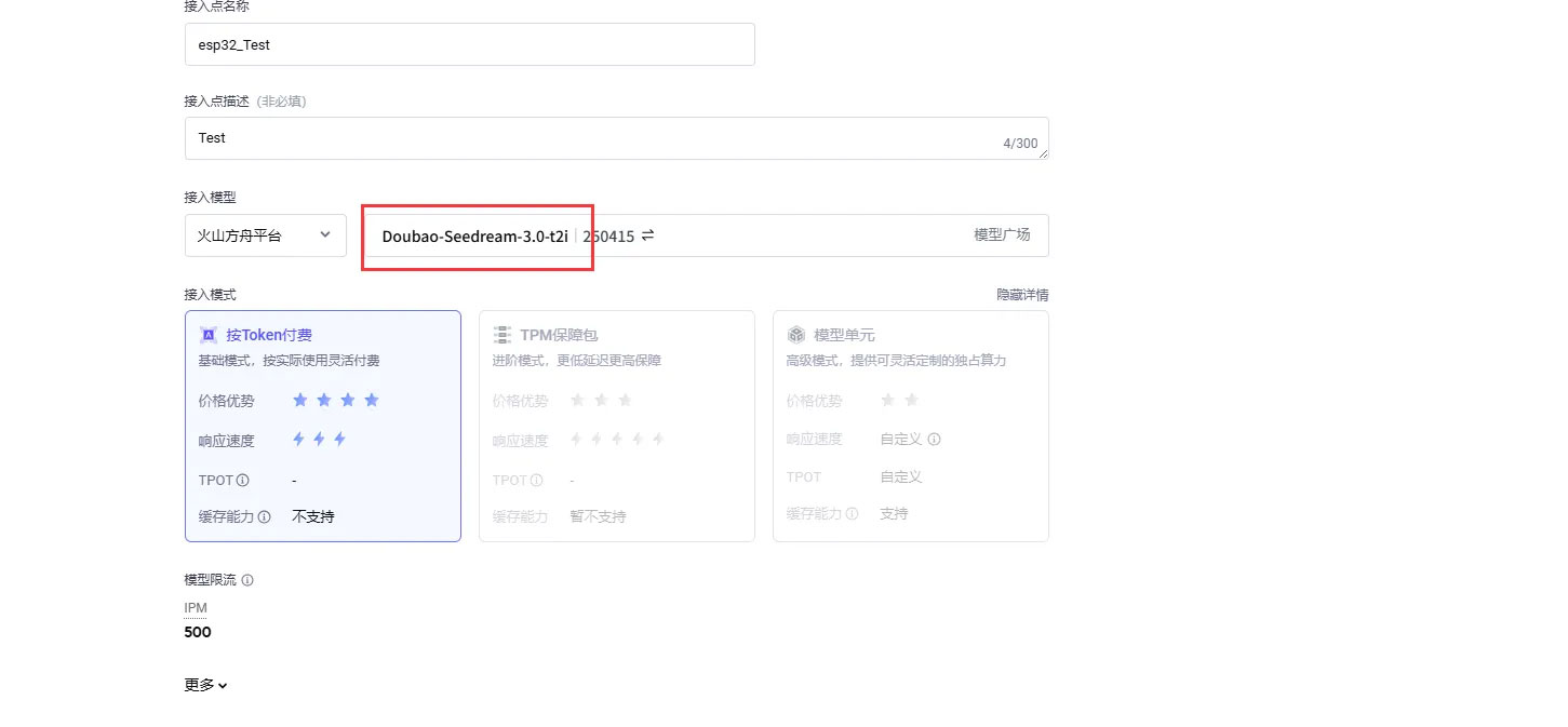
- Create the corresponding model. Be careful not to select the wrong model, as shown:
- Copy the corresponding key, model, and URL as shown:
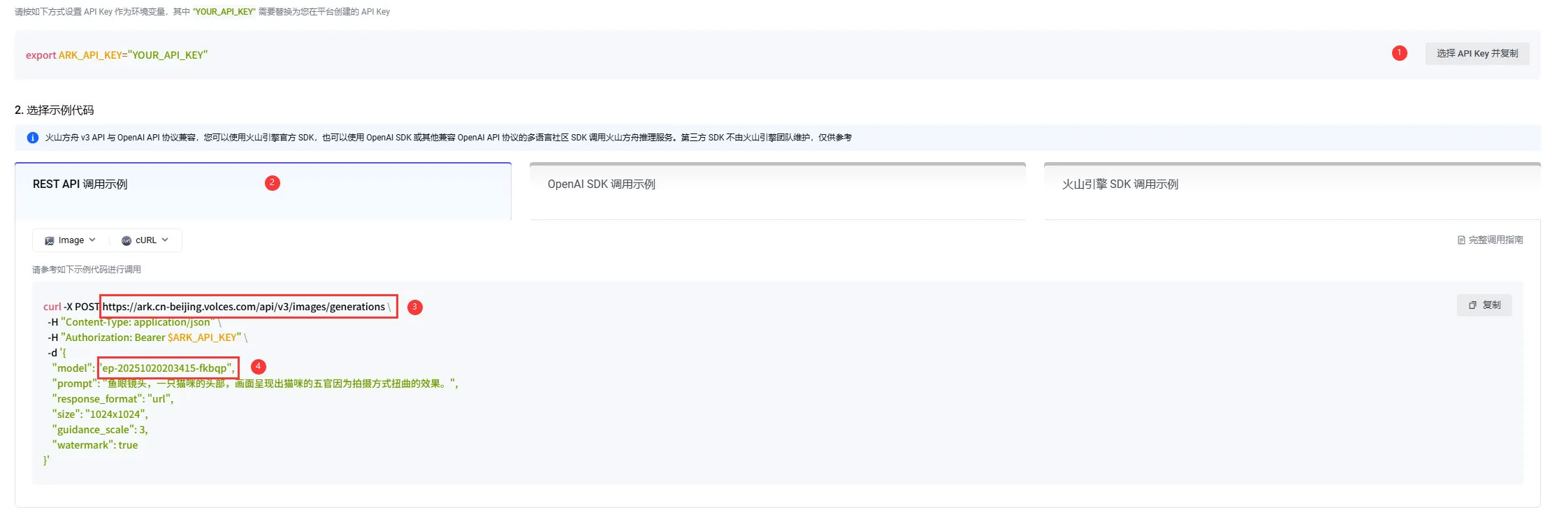
- Paste the copied
url,model, andkeyinto the corresponding key‑value fields in theconfig.txtfile located in thesdcard->imgdirectory (see step 1, second image). New users can claim free Tokens.
Resources
1. Hardware Resources
Development Board Design Files
2. Technical Manuals
ESP32-S3 Chip Official Manuals
Datasheets
3. Demo
4. Software Tools
- Arduino:
- VScode:
- Firmware Flashing Tool:
Support
Monday-Friday (9:30-6:30) Saturday (9:30-5:30)
Email: services01@spotpear.com
[Tutorial Navigation]
- Features
- Onboard Resources
- Interface Introduction
- Dimensions
- orking with Arduino
- ESP-IDF
- ESP-IDF Getting Started
- Setting Up Development Environment
- Demo
- Resources
- Support