


- sales/support
Google Chat:---
- sales
+86-0755-88291180
- sales01
sales@spotpear.com
- sales02
dragon_manager@163.com
- support
tech-support@spotpear.com
- CEO-Complaints
zhoujie@spotpear.com
- Only Tech-Support
WhatsApp:13246739196
- Purchase/Shipping/Refund
WhatsApp:13424403025
- HOME
- >
- ARTICLES
- >
- Jetson Series
- >
- Jetson Kits
UGV-Beast-PT-Jetson-Orin-AI-Kit Product Tutorial
Jetson 01 Introduction to JupyterLab And Robotics Basics
Introduction to Robotics Basics
Control Architecture
Our robot employs a dual-controller architecture (akin to a dual-controller structure), with the host potentially being a Raspberry Pi, Jetson Nano, Orin Nano, or other similar single-board computers equipped with a 40PIN interface. The sub-controller utilizes an ESP32 to control the robot's peripherals, read sensor data, and manage closed-loop speed control for the motors using PID controllers.
The dual controllers communicate through serial connections using JSON-formatted instructions. For more specific communication content, users can refer to the documentation of the sub-controller. For a new beginner, you do not need to understand those commands, you only need to follow the tutorial documentation to call common commands or encapsulated functions.
Leveraging the Advantages of a "Dual-controller" Architecture
1. Jetson or other single-board computers as the primary processing unit handle complex tasks, such as processing visual information, and the ESP32 as a secondary controller dedicated to managing peripherals and sensors, exemplifies a modular design that enhances system flexibility and scalability.
2. The single-board computers are tasked with higher-level processing and decision-making, while the ESP32 handles real-time, low-level tasks such as motor control. This division of tasks allows each component to focus on its functionality, optimizing the system's overall performance.
3. This architecture efficiently allocates processing power and I/O resources, reducing the strain on a singular system and enhancing efficiency.
4. Communication between components is facilitated through serial connections using JSON, which not only streamlines data transfer but also improves readability, easing the debugging and expansion processes.
5. For hobbyists and makers with limited budgets, this "dual-controller" architecture strategy offers a way to maintain high performance while minimizing the costs and complexity of the system.
Basic Tutorial on Interactive Development Using JupyterLab
What is JupyterLab?
- Interactive Development Environment: JupyterLab is an open-source interactive development environment that offers an easy-to-use interface for coding, running experiments, and viewing data.
- Ideal for Data Science and Machine Learning: Initially designed for data science and machine learning, its flexibility and ease of use also make it an excellent choice for robotic programming and experimentation.
- Based on Web Technologies: JupyterLab integrates seamlessly with web technologies, providing a robust platform for various computing tasks.
Benefits of Developing with JupyterLab
1. The User-Friendly Programming Environment of JupyterLab:
JupyterLab's clean and intuitive user interface makes programming and experimentation more accessible to beginners. Its interactive notebooks allow for easy code writing and testing, ideal for novices to explore and learn gradually.
2. Immediate Feedback and Visualization of Results:
JupyterLab provides instant feedback, enabling users to see the effects of code changes immediately, which is invaluable for debugging and learning. Its convenient data visualization capabilities aid in understanding the behaviors and performance of robots.
3. Support for Multiple Programming Languages:
JupyterLab accommodates various programming languages, including Python, offering flexibility for users of all skill levels.
4. Customization and Extension Capabilities:
JupyterLab's high customizability and extensibility allow users to add new features or tools as needed.
5. Cross-Platform Accessibility
As a web-based tool, JupyterLab boasts excellent cross-platform capabilities, running on different operating systems and accessible through a browser.
Basic Usage of JupyterLab
- Learning Resources: Refer to JupyterLab's official documentation for a comprehensive learning guide: https://jupyterlab.readthedocs.io/en/latest/getting_started/overview.html
- Given that our interactive tutorials are conducted using Jupyter Notebook (.ipynb) files, we will introduce some basic usage techniques here.
What is a Jupyter Notebook (.ipynb) Document
- Jupyter Notebooks (.ipynb) are documents that combine executable code with narrative text (Markdown), equations (LaTeX), images, interactive visualizations, and other rich output elements.
Switching Document Themes
- Our default theme is the light-colored Jupyter Dark.
- You can switch to a dark theme based on your preference by clicking on Settings - Theme - JupyterLab Dark at the top of the interface.
COMMAND / EDIT MODE
JupyterLab operates in two modes: COMMAND mode and EDIT mode.
- COMMAND Mode:
In COMMAND mode, you can quickly perform notebook-wide operations, such as adding or deleting cells, moving cells, changing cell types, etc. In this mode, the cell border is gray. You can enter COMMAND mode by pressing the Esc key.
- EDIT Mode:
EDIT mode allows you to enter or modify code or text within a cell. In this mode, the cell border is blue. You can enter EDIT mode by clicking inside a selected cell or pressing the Enter key.
Cell Operations
In JupyterLab, you can perform the following operations:
- In COMMAND mode, use the up and down arrow keys to select cells.
- Add Cell Below: You can add a new cell below the current cell by clicking the "+" button on the toolbar or using the shortcut key B (in COMMAND mode).
- Add Cell Above: You can add a new cell above the current cell by clicking the "+" button on the toolbar or using the shortcut key A (in COMMAND mode).
- Delete Cell: Press D,D (press the D key twice in quick succession in COMMAND mode) to delete the currently selected cell.
- Copy Cell: Use the shortcut key C in COMMAND mode.
- Paste Cell: Use the shortcut key V in COMMAND mode.
- Cut Cell: Use the shortcut key X in COMMAND mode.
- Undo: Use the shortcut key Z in COMMAND mode.
- Redo: Use the shortcut key Shift + Z in COMMAND mode.
- Convert the Current Cell to Code Block: Use the shortcut key Y in COMMAND mode.
- Convert the Current Cell to Markdown: Use the shortcut key M in COMMAND mode.
- Switch Cell Type: You can set a cell as a code cell, Markdown cell, or raw cell. This can be done using the toolbar dropdown menu or the shortcut keys Y (for code cell) and M (for Markdown cell) in COMMAND mode.
- Run Cell: You can execute the current cell and automatically move to the next cell by clicking the "RUN" button on the toolbar or using the shortcut key Shift + Enter.
Saving and Exporting
- Save Notebook: You can save your notebook by clicking the "SAVE"
- button on the toolbar or using the shortcut key S (in COMMAND mode).
- Export Notebook: JupyterLab allows you to export notebooks in various formats, including HTML, PDF, Markdown, etc. This can be done through the File -> Export Notebook As... menu option.
- A JupyterLab Kernel acts as a computational engine that executes the code written by users in their notebooks.
- Each notebook is linked to a Kernel, which can be programmed in various languages such as Python, R, or Julia. Kernels also have access to resources like memory and CPU.
- When opening subsequent .ipynb tutorial documents, you'll need to manually select the Kernel in the notebook to ensure the robot-related code blocks execute correctly.
- To do this, click on the Kernel option next to the "⭕" at the top right corner of the notebook tab and choose Python 3 (ipykernel) from the dropdown menu.
- Starting: When you open a Jupyter notebook, the associated Kernel will automatically start, indicated by a small green dot appearing in front of the corresponding note in the file list.
- Restarting: If the Kernel crashes or you need to clear the current session's state, you can restart the Kernel via "Kernel" -> "Restart Kernel...".
- Stopping: To stop the Kernel of a running note, go to "Kernel" -> "Shut Down Kernel" within the note interface. To stop all Kernels, use "Kernel" -> "Shut Down All Kernels".
- Note: If a notebook's Kernel is using the camera and isn't stopped, it will continue to occupy this resource, preventing other notebooks from using it normally. Stopping the notebook's Kernel is necessary for others to function correctly.
- Run a Single Code Block: Select the code block you wish to run and click the "▶︎" button on the toolbar or use the Shift + Enter shortcut. This action will execute the current code block and select the next one.
What is a JupyterLab Kernel?
Setting the Kernel for a Robotic Virtual Environment
Kernel Management
Running Code Blocks
After selecting the correct Kernel, you can run code blocks within the notebook. In JupyterLab, code blocks are fundamental components of a notebook. Here's how to execute them:
print("test text in jupyterlab")- Run All Code Blocks: You can also execute all code blocks in the entire notebook by clicking the Run menu on the toolbar and selecting Run All Cells.
These basic operations enable the efficient use of JupyterLab for various tasks. For more advanced features and detailed usage guidelines, refer to JupyterLab's official documentation.
for i in range(0, 10):
print(i)- Stopping a Code Block's Execution: If you need to stop a code block that's currently running, you can click the "■" button on the toolbar.
With these basic operational methods, you can effectively use JupyterLab for various tasks. More advanced features and detailed guides can be found in JupyterLab's official documentation.
Deleting Code Block Outputs
- To delete the output of a single code block, select the block and then click Edit - Clear Cell Output from the menu above.
- To delete the outputs of all code blocks, click Edit - Clear Outputs of All Cells from the menu above.
For More Advanced Content
- You can refer to JupyterLab's official documentation for further learning: https://jupyterlab.readthedocs.io/en/latest/getting_started/overview.html
Jetson 02 Python Chassis Motion Control
Python Chassis Motion Control
In this chapter, we'll provide a Python demo for controlling the motion of a robot's chassis. This approach can be adapted to other programming languages for similar motion control tasks.
Control Mechanism Overview
We utilize code blocks within JupyterLab to compose JSON commands. These commands are then sent to the slave controller via the GPIO serial port on a Jetson (the default baud rate for communication with the slave controller is 115200). Upon receiving these commands, the slave controller executes the specified actions.
Further sections will delve into the variety of commands that can be sent to the slave controller. Alternatively, you might choose to implement this function in a different programming language or develop a dedicated application for the host controller.
Design Advantages
Adopting a dual-controller architecture significantly liberates the resources of the host device. In this setup, the host controller (SBC such as Raspberry Pi or Jetson) acts as the "brain", while the ESP32 slave controller (sub-controller) serves as a "cerebellum-like" entity handling the lower-level motion controls. This division of tasks allows the host to focus on high-level tasks like vision processing and decision-making, while the sub-controller efficiently manages precise movement control and other low-level tasks. Such an arrangement ensures that the sub-controller can maintain accurate wheel rotation speeds through high-frequency PID control, without overburdening the host with computationally intensive tasks.
Main Program (app.py)
The main program of the product, app.py, automatically executes upon booting due to the configuration set by autorun.sh (which is pre-configured in the product). Running app.py occupies the GPIO serial port and the camera, which might lead to conflicts or errors if other tutorials or programs require these resources. Ensure to disable the auto-start of app.py before proceeding with development or learning.
As app.py employs multithreading and uses crontab for autostart, typical commands like sudo killall python won't suffice to terminate it. You would need to comment out the relevant line in crontab and reboot the device.
crontab -e
Upon your first use of this command, you will be prompted to select an editor to open the crontab file. It is recommended to choose nano by entering the corresponding number for nano, followed by pressing the Enter key to confirm.
Use the # symbol to comment out the line containing ...... app.py.
# @reboot ~/ugv_pt_rpi/ugv-env/bin/python ~/ugv_pt_rpi/app.py >> ~/ugv.log 2>&1
@reboot /bin/bash ~/ugv_pt_rpi/start_jupyter.sh >> ~/jupyter_log.log 2>&1
Note: Make sure not to comment out the line containing start_jupyter.sh, as doing so will prevent JupyterLab from launching on startup, disabling your access to interactive tutorials.
To exit and save the changes, after editing the content of crontab, press Ctrl + X to exit nano. Since you have made edits to the crontab file, it will ask if you want to save the changes (Save modified buffer?). Enter the letter Y and then press Enter to exit and save the modifications.
After restarting the device, the main program will no longer run automatically upon boot-up, allowing you to freely use the tutorials within JupyterLab. If you wish to re-enable the automatic execution of the main program at startup in the future, you can reopen the crontab file using the method described above. Simply remove the # symbol in front of the @ symbol, then exit and save the changes. This will restore the automatic startup functionality of the main program.
Chassis Control Demo
In the following demo, it's crucial to use the correct device name and baud rate (default 115200) that matches the sub-controller.
Before executing the code block below, ensure the robot is elevated so that the drive wheels are off the ground. Activating the code will cause the robot to move; take precautions to prevent it from falling off the table.
from base_ctrl import BaseController
import time

base = BaseController('/dev/ttyTHS0', 115200)

# The wheel rotates at 0.2 m/s for 2 seconds and then stops
base.send_command({"T":1,"L":0.2,"R":0.2})
time.sleep(2)
base.send_command({"T":1,"L":0,"R":0})
By invoking the code block mentioned above, the Raspberry Pi will initially send the command {"T":1,"L":0.2,"R":0.2} (the structure of commands will be discussed in more detail in later chapters). This command starts the wheels turning. After a two-second interval, the Raspberry Pi will send another command {"T":1,"L":0,"R":0}, causing the wheels to stop. It's important to note that even if the command to stop the wheels isn't sent, the wheels will still cease turning if no new commands are issued. This is due to a heartbeat function built into the sub-controller. The purpose of this heartbeat function is to halt the current motion command automatically if the host controller hasn't sent any new commands to the sub-controller for an extended period. This function is designed to prevent continuous motion of the sub-controller in case the host encounters a problem that leads to a freeze or crash.
If you want the robot to continue moving indefinitely, the master control unit needs to cyclically send motion control commands every 2 to 4 seconds.
Chassis Model Selection
You may find that the direction or speed of the robot's wheels does not match your expectations after inputting the motion control commands. This could be because, before controlling the chassis, you need to set the type of chassis. Each time you run the main demo (app.py), the chassis type is automatically configured, and the configuration parameters are stored in config.yaml. This ensures that the chassis is controlled according to the correct parameters. By default, the chassis needs to be configured once by the host computer every time it is powered on. You can send the following commands to the chassis to set its type:
"main" value means the chassis type:
- 1: RaspRover (4-wheel 4WD chassis)
- 2: UGV Rover (6-wheel 4WD chassis)
- 3: UGV Beast (off-road tracked chassis)
"module" value means the module type:
- 0: can be set whether install the pan-tile module or not
- 1: robotic arm module (if there is not a robotic arm installed, report errors when the chassis Ping fails.)
- 2: pan-tilt module (if there is not a pan-tilt module installed, report errors when the chassis Ping fails.)
For example, if you use the UGV Rover with the pan-tilt module, you can send the following commands to the slave computer to set the chassis type:
{"T":900,"main":2,"module":0} or {"T":900,"main":2,"module":2}- If you don't require chassis feedback on the pan-tilt's angle information (intended for user secondary development, not included in the demos), it's recommended to use the former one.
You can modify the JSON parameter to set the chassis model in the following demo block according to your products:
base.send_command({"T":900,"main":2,"module":0})Then the following code block is executed to control the chassis, and the wheels turn in the right direction and at the right speed.
base.send_command({"T":1,"L":0.2,"R":0.2})
time.sleep(2)
base.send_command({"T":1,"L":0,"R":0})
Chassis Steering Principle
The earlier demo allows you to make the robot move forward for two seconds before stopping. Further adjustments to the parameters can control the direction of the chassis, based on the differential steering principle.
When turning, the inner wheels (on the side towards which the turn is made) travel a shorter distance and thus should rotate slower to maintain stability. The differential gear system achieves this by allowing the drive wheels to rotate at different speeds. Usually, the outer wheels (on the opposite side of the turn) rotate faster than the inner wheels. This variation in speed results in the turning motion of the vehicle, allowing it to steer in the intended direction.
You can control the vehicle's steering by assigning different target linear velocities to each wheel, thus achieving maneuverability and easily adjustable turning radii.
Jetson 03 Pan-tilt And LED Control
Pan-tilt Control And LED Control
Pan-tilt Control
Introduction
The product (PT Version only) with pan-tilt has two servos, that is, pan servo and tilt servo, and the rotation range is ±180° (360° in total). The tilt servo controls the horizontal rotation, and the range is -45°~90° (135° in total)
For products without a pan-tilt mechanism, users can expand this function by adding a pan-tilt mechanism to the RaspRover platform themselves.
# Import libraries for chassis control
from base_ctrl import BaseController

base = BaseController('/dev/ttyTHS0', 115200)
In the code block above, we import and instantiate the library for base control. Next, we control the movement of the pan-tilt by changing the angles of the pan and tilt servos.
Modify the values in the following code:
- input_x: Angle of the pan servo, within the range of ±180° (total range of 360°).
- input_y: Angle of the tilt servo, within the range of -45° to 90° (total range of 135°).
- input_speed: Speed of the pan-tilt movement. When the speed value is 0, the movement is at its fastest.
- input_acc: Acceleration at the start and end of the pan-tilt movement. Smaller values result in smoother acceleration and deceleration. When the acceleration value is 0, the maximum acceleration is applied.
Run the code below to observe the pan-tilt move 45° to the right and upward before stopping.
input_x = 45
input_y = 45
input_speed = 0
input_acc = 0

base.gimbal_ctrl(input_x, input_y, input_speed, input_acc)
In addition to controlling the pan-tilt movement by changing the angles of the two servos, you can also directly control its continuous movement.
Modify the values in the code below:
- input_x: the rotation mode of the pan servo. When the value is -1, it represents continuous rotation to the left (clockwise); when the value is 1, it represents continuous rotation to the right (counterclockwise); when the value is 0, it indicates stopping the rotation.
- input_y: the rotation mode of the tilt servo. When the value is -1, it represents continuous downward rotation (tilting down); when the value is 1, it represents continuous upward rotation (tilting up); when the value is 0, it indicates stopping the rotation.
- input_speed: speed of the pan-tilt movement.
If both input_x and input_y are set to 2, the pan-tilt will automatically return to its middle position.
Run the code below, and the pan-tilt will move to the left until it reaches 180° and then stop.
input_x = -1
input_y = 0
input_speed = 0

base.gimbal_base_ctrl(input_x, input_y, input_speed)
Run the following code, the pan-tilt will move upward until it reaches 90° and then stop.
input_x = 0
input_y = 1
input_speed = 0

base.gimbal_base_ctrl(input_x, input_y, input_speed)
To make the pan-tilt return to its middle position, run the following code:
input_x = 2
input_y = 2
input_speed = 0

base.gimbal_base_ctrl(input_x, input_y, input_speed)
LED Control
Introduction
The WAVE ROVER and UGV series products feature a drive board integrated with two 12V switches (the actual maximum voltage varies with the battery voltage). These switches are controlled by ESP32's IO4 and IO5 pins via MOS tubes. Each switch has two ports, totaling 4x 12V switch control ports. By default, IO4 controls the chassis LED (WAVE ROVER does not have a chassis LED), and IO5 controls the LED. You can control the switching of these two switches and adjust the voltage level by sending the corresponding commands to the sub-controller. However, due to the inherent delay in MOSFET control, there may not be a linear relationship between the PWM output from the ESP32's IO and the actual voltage output.
For products without LEDs, you can expand the 12.6V withstand LED on these two 12V switches (in general, 12V withstand is also acceptable for safety and battery protection, the product's UPS will not charge the battery above 12V). You can also expand other peripherals on the remaining switch control interfaces, such as a 12V withstand water gun gearbox, which can be directly connected to the interface controlled by IO5 to achieve automatic aiming and shooting functionality.
To run the code within the code block, you can select the desired code block and then press Ctrl+Enter to run the program. If you are using JupyterLab on a mobile device or tablet, you can press the play button above the code block to run it.
In the above code block, we import and instantiate the library for controlling the chassis. Next, we control the switch of the IO4 interface. The variable IO4_PWM represents the PWM output of the ESP32's IO4 pin, with a range of 0-255. When this variable is set to 0, the switch controlled by IO4 is turned off; when set to 255, the voltage output of the switch controlled by IO4 approaches the battery voltage of the UPS (the current voltage of the three lithium batteries in series inside the UPS).
Run the following code block to turn on the switch controlled by IO4 (turn on the chassis headlights). Note: WAVE ROVE does not have chassis headlights, so running the following code block will not make any changes. You need to run the next code block to turn on the headlights, which are located on the camera gimbal. If the product is not equipped with a camera gimbal, there are no headlights.
IO4_PWM = 255
IO5_PWM = 0

base.lights_ctrl(IO4_PWM, IO5_PWM)
To turn on the switch controlled by interface IO5 (turn on the pan-tilt LED), run the following code block:
Note: If the product does not come with a camera pan-tilt, there are no LED lights.
IO4_PWM = 255
IO5_PWM = 255

base.lights_ctrl(IO4_PWM, IO5_PWM)
If your product comes with LED, they should all be tilted up by now. You can run the following code block to decrease the brightness of the LED lights.
IO4_PWM = 64
IO5_PWM = 64

base.lights_ctrl(IO4_PWM, IO5_PWM)
Finally, run the following code block to turn off the LEDs.
base.lights_ctrl(0, 0)Run a code block here that integrates the pan-tilt functionality:
import time
base.gimbal_ctrl(0, 0, 0, 0)
base.lights_ctrl(255, 255)
time.sleep(0.3)
base.gimbal_ctrl(45, 0, 0, 0)
base.lights_ctrl(0, 0)
time.sleep(0.3)
base.gimbal_ctrl(-45, 0, 0, 0)
base.lights_ctrl(255, 255)
time.sleep(0.3)
base.gimbal_ctrl(0, 90, 0, 0)
base.lights_ctrl(0, 0)
time.sleep(0.3)
base.gimbal_ctrl(0, 0, 0, 0)
Jetson 04 OLED Screen Control
This tutorial demonstrates how to control an OLED display connected to an ESP32 module using JSON commands. OLED displays are widely used for showing various types of information, such as text and images.
OLED Screens Basics
OLED displays communicate with the ESP32 module via the I2C (Inter-Integrated Circuit) interface. These displays are capable of showing custom text content and support multi-line display.
The product comes with an OLED display that communicates with the ESP32 module through the I2C interface. Upon powering up, the display automatically shows some basic information about the slave device. The content displayed on the screen can be altered by sending JSON commands from the host device.
OLED Screen Control JSON Commands
- {"T":3,"lineNum":0,"Text":"putYourTextHere"}
- Controls the display to show custom content.
- lineNum refers to the line number, and a single JSON command can change the content of one line. For the commonly used 0.91-inch OLED displays, the value of lineNum can be 0, 1, 2, or 3, allowing for four lines in total.
- Text is the content you wish to display on that line. If the content exceeds the line length, it will automatically wrap to the next line, potentially overwriting the last line's content.
lineNum refers to the line number. A single JSON command can modify the content of one line. When the subordinate machine receives a new command, the default OLED display screen at startup will disappear, replaced by the content you've added. For most products that use a 0.91-inch OLED display, the value of lineNum can be 0, 1, 2, or 3, allowing for a total of four lines. Text is the textual content you wish to display on that line. If the content for a line is too long, it will automatically wrap to the next line, potentially overwriting the content on the last line.
from base_ctrl import BaseController

base = BaseController('/dev/ttyTHS0', 115200)

#Modify the OLED display content
base.send_command({"T":3,"lineNum":0,"Text":"this is line0"})
base.send_command({"T":3,"lineNum":1,"Text":"this is line1"})
base.send_command({"T":3,"lineNum":2,"Text":"this is line2"})
base.send_command({"T":3,"lineNum":3,"Text":"this is line3"})
Running the provided code block will display four lines of text on the OLED:
this is line0

this is line1

this is line2

this is line3
Displaying Dynamic Information on OLED
The tutorial above outlined a method for displaying simple text on the OLED screen. We will now proceed with a slightly more complex example. Running the following code block will display the current time on the OLED screen. Note that the time displayed might not be accurate due to potential discrepancies with the Raspberry Pi's clock. This example serves to demonstrate how to update the screen content in the main program, where we employ this method to display real-time information such as the device's IP address and operational status on the OLED screen.
# Import the datetime class from the datetime module to fetch and manipulate the current date and time.
from datetime import datetime
#  Import the time module, primarily used for delay processing within the program.
import time

# Create an infinite loop using while True to allow the program to run continuously.
while True:
    # Use datetime.now().strftime("%H:%M:%S") to obtain the current time and format it as "hour:minute:second".
    current_time = datetime.now().strftime("%H:%M:%S")
    # Utilize the base.send_command method to send a command that includes the current time.
    base.send_command({"T":3,"lineNum":0,"Text":current_time})
    # Use time.sleep(1) to pause the program for 1 second, ensuring that the time is updated and a command is sent every second.
    time.sleep(1)
Running the last code block, you'll observe the first line of the OLED screen updating to show the current time, refreshing every second. This function runs in an infinite loop, which can be terminated by clicking the stop button(■) above.
Jetson 05 Building UI Interfaces in JupyterLab
In JupyterLab, constructing UI interfaces is commonly achieved using the "ipywidgets" library, offering a simple yet powerful method to create interactive user interfaces. Here are the detailed steps:
Importing Required Libraries
The ipywidgets library is pre-installed in our product. If you encounter a library not found error when executing code blocks, you can install the necessary libraries for the UI interface by running pip install ipywidgets.
Select the following code block and press Ctrl + Enter to execute the code.
import ipywidgets as widgets
from IPython.display import display
Creating UI Components
We can use various components from the ipywidgets library to build our UI interface, such as text boxes, buttons, output boxes, etc. For example:
# Creating a text box
text = widgets.Text(description='Input Name:')

# Creating a button
button = widgets.Button(description="Say Hi")

# Creating an output box
output = widgets.Output()
Defining Event Handling Functions
We need to define a function to handle user interaction events. In this example, we'll define a function to handle the button on click events and display a greeting in the output box.
# Define a function `greet_user` that takes one parameter, `sender`, where `sender` represents the object that triggered the event, such as a button
def greet_user(sender):
    # Use the `with` statement and the `output` object to capture the output of the `print` function, so it displays in the expected output area
    # output is a pre-defined output object
    with output:
        # Use the `print` function to output a greeting message, where the `format` method is used to insert the current value of the `text` widget into the string
        # "{}" serves as a placeholder that the `format` function will replace with the value of `text.value`
        print("Hi, {}".format(text.value))

# Use the `on_click` method to link the button's click event with the `greet_user` function.
# When the user clicks this button, the `greet_user` function will be called.
button.on_click(greet_user)
Displaying the UI
Finally, we place all UI components in a layout and display them using the display function.
#Place all components in a vertical layout
ui = widgets.VBox([text, button, output])

# Display the UI
display(ui)
By following these steps, we can build a simple UI interface in JupyterLab. Users can enter content in the text box, and upon clicking the button, the program will display a corresponding greeting in the output box based on the input content.
Jetson 06 Retrieving Chassis Feedback Information
How to Retrievie Chassis Feedback Information
Upon startup, the lower-level systems of the product continuously send various types of feedback information to the upper-level systems. This feedback can be utilized to ascertain the current operational status of the product.
Typically, you would continuously monitor the feedback information from the lower-level systems. However, in this example, we will retrieve a single piece of JSON feedback information from the slave systems (you can continuously receive feedback information by commenting out or deleting the break line).
Select the code block below and run it using Ctrl + Enter. The loop will exit and display the feedback information after receiving the first complete JSON message with a "T" value of 1001. The feedback information includes the current wheel speed, IMU data, gimbal angle (if installed), arm angle (if installed), power voltage, and other data.
from base_ctrl import BaseController
import json

base = BaseController('/dev/ttyTHS0', 115200)
# Implement an infinite loop to continuously monitor serial port data
while True:
    try:
        # Read a line of data from the serial port, decode it into a 'utf-8' formatted string, and attempt to convert it into a JSON object
        data_recv_buffer = json.loads(base.rl.readline().decode('utf-8'))
        # Check if the parsed data contains the key 'T'
        if 'T' in data_recv_buffer:
            # If the value of 'T' is 1001, print the received data and break out of the loop.
            if data_recv_buffer['T'] == 1001:
                print(data_recv_buffer)
                break
    # If an exception occurs while reading or processing the data, ignore the exception and continue to listen for the next line of data.
    except:
        pass
Non-Blocking Method for Receiving JSON Information via Serial Port
The following code is intended for understanding the underlying principles of reading JSON information from a serial port and should not be executed.
class ReadLine:
    # Construct a constructor to initialize an instance of the ReadLine class
    # s: The serial port object passed in for communication with the serial port.
    def __init__(self, s):
        self.buf = bytearray()  # Initialize a byte array to store data that has been read from the serial port but not yet processed

        self.s = s  # Store the passed-in serial port object for subsequent use in reading serial port data

	def readline(self):
		i = self.buf.find(b"\n") # Check if there is a newline character in the buffer
		if i >= 0:
			r = self.buf[:i+1] # If there is a newline character, extract the data before the newline character
			self.buf = self.buf[i+1:] # Update the buffer by removing the data that has been processed
			return r
		while True:
			i = max(1, min(512, self.s.in_waiting)) # Retrieve the number of bytes available for reading, up to a maximum of 512 bytes
			data = self.s.read(i) # Read data from the serial port
			i = data.find(b"\n") # Search for a newline character
			if i >= 0:
				r = self.buf + data[:i+1] # If a newline character is found, merge the data that has been read with the data in the buffer
				self.buf[0:] = data[i+1:] # Update the buffer by removing the processed data
				return r
			else:
self.buf.extend(data) # If a newline character is not found, add the data to the buffer- This method is designed for reading data from a serial port and returning a complete line of JSON data, delimited by a newline character (\n).
- If there's already a complete line of data in the buffer, it returns that line directly.
- If the buffer does not contain a complete line, the method uses the in_waiting function to check the number of bytes available for reading in the serial port's buffer, reading up to 512 bytes at a time.
- The data read from the serial port is then merged with the data in the buffer.
- The method checks the newly read data for a newline character. If found, it extracts the complete line of data and updates the buffer.
- If no newline character is found, the new data is added to the buffer, and the method continues reading until a newline character is found.
Function Characteristics
- Non-blocking: This function employs a non-blocking reading approach, meaning it does not halt the program's execution even if there's no data to read from the serial port. It waits until data is available.
- Efficient: By using a small buffer and limiting the read amount to a maximum of 512 bytes at a time, the function reduces memory consumption and promptly processes data to prevent buffer overflow.
- Flexible: The function can flexibly read data of any length and automatically deals with data split by newline characters. This makes it particularly suitable for reading structured data like JSON.
- Reliable: The function is designed to account for various scenarios, such as insufficient buffer data or the absence of newline characters in the read data, ensuring the accuracy and stability of the read operations.
- Ideal for Real-time Use: This function is especially suitable for real-time reading of JSON data from a serial port, especially in scenarios where non-blocking reads are required.
Jetson 07 Controlling Slave Devices with JSON Commands
This product is developed using a dual-controller architecture, where the main control unit communicates with the slave device via serial ports (Jetson through GPIO serial ports). It's important to note that this chapter serves as a precursor to a more detailed exploration of the JSON command set for the slave device, and its content is similar to the previous chapter on Python chassis movement control. If you're already familiar with that chapter, you might find this overview sufficient.
Advantages of JSON data format
JSON (JavaScript Object Notation) is a lightweight data-interchange format that has become one of the standards for data transmission on the internet. Here are some advantages of JSON:
- High Readability: JSON uses a text format that is easy for humans to read and write. It organizes data in key-value pairs, making it more readable and understandable during transmission and storage.
- Lightweight: JSON syntax is more concise and compact compared to other data formats like XML, making it more lightweight. This reduces the size of data transmissions and network bandwidth usage, improving transmission efficiency.
- Ease of Parsing: The simple and clear data structure of JSON makes it easy to parse and serialize. Nearly all programming languages offer libraries for parsing and generating JSON, allowing developers to easily work with JSON data.
- Wide Language Compatibility: JSON is supported in almost all programming languages, enabling convenient data exchange and communication across different platforms and systems.
- Support for Multiple Data Types: JSON supports a variety of data types, including strings, numbers, boolean values, arrays, and objects. This flexibility allows it to represent a wide range of data structures.
- Seamless Integration with Web Technologies: JSON originated from JavaScript, making its integration with web technologies very tight. It is highly compatible with the JavaScript language, making it convenient to use in web applications.
A Simple Example of Controlling a Subordinate Device with JSON Commands
In the following example, it's crucial to use the correct GPIO device name and the same baud rate as the subordinate device (default is 115200).
Before executing the code block below, ensure the robot is elevated so that the drive wheels are off the ground. Activating the code will cause the robot to move; take precautions to prevent it from falling off the table.
from base_ctrl import BaseController
import time

base = BaseController('/dev/ttyTHS0', 115200)

# The wheel rotates at 0.2 m/s for 2 seconds and then stops
base.send_command({"T":1,"L":0.2,"R":0.2})
time.sleep(2)
base.send_command({"T":1,"L":0,"R":0})
By invoking the code block mentioned above, the Raspberry Pi will initially send the command {"T":1,"L":0.2,"R":0.2} (the structure of commands will be discussed in more detail in later chapters). This command starts the wheels turning. After a two-second interval, the Jetson will send another command {"T":1,"L":0,"R":0}, causing the wheels to stop. It's important to note that even if the command to stop the wheels isn't sent, the wheels will still cease turning if no new commands are issued. This is due to a heartbeat function built into the sub-controller. The purpose of this heartbeat function is to halt the current motion command automatically if the host control hasn't sent any new commands to the sub-controller for an extended period. This function is designed to prevent continuous motion of the sub-controller in case the host encounters a problem that leads to a freeze or crash.
If you want the robot to continue moving indefinitely, the host control needs to cyclically send motion control commands every 2 to 4 seconds.
08 Sub-controller JSON Command Set
In the previous chapter, we introduced a simple demo where we sent motion control commands from the host to the sub-controller. The microcontroller is capable of receiving a wide variety of commands, and in this chapter, we will introduce these commands.
Composition of JSON Commands
Taking the command {"T":1,"L":0.2,"R":0.2} sent in the previous chapter as an example, the T value in this JSON data represents the command type, while the L and R values represent the target linear velocities for the left and right wheels, respectively. The unit for linear velocity is by default meters per second (m/s). In summary, this command is a motion control command where the motion parameters are the target linear velocities for the left and right wheels.
All subsequent JSON commands will include a T value to define the command type, but the specific command parameters will vary depending on the type of command.
JSON Command Set
You can view the definitions of these commands in the json_cmd.h file of our open-source microcontroller routine, or add new sub-controller functionalities yourself.
Motion Control Commands
These commands are fundamental to the mobile robot and are used for motion-related control functions.
Each command below includes three parts: an example, a brief introduction, and a detailed description.
CMD_SPEED_CTRL
- {"T":1,"L":0.5,"R":0.5}
- Sets the target linear velocity for both wheels (velocity closed-loop control).
L and R represent the target linear velocities for the left and right wheels, respectively, in m/s. Negative values indicate reverse rotation and 0 means stop. The range of target linear velocities depends on the motors/reducers/wheel diameters used in the product, and the relevant calculation formulas can be found in the open-source microcontroller routine. It's important to note that for chassis using brushed DC motors, when the given target velocity's absolute value is very small (but not 0), the motor's poor low-speed performance may cause significant speed fluctuations during movement.
CMD_PWM_INPUT
- {"T":11,"L":164,"R":164}
- Sets the PWM value for both drive wheels (velocity open-loop control).
L and R represent the PWM values for the left and right wheels, respectively, with a range of -255 to 255. Negative values indicate the reverse direction and an absolute value of 255 means 100% PWM, indicating full power operation for that wheel.
CMD_ROS_CTRL
- {"T":13,"X":0.1,"Z":0.3}
- ROS control (velocity closed-loop control).
This command is for ROS-based host computer control of the chassis movement. X represents the linear velocity in m/s, which can be negative; Z represents the angular velocity in rad/s, which can also be negative.
CMD_SET_MOTOR_PID
- {"T":2,"P":20,"I":2000,"D":0,"L":255}
- PID controller settings.
This command is used to tune the PID controller. The PID parameters in the example above are the default parameters for this product. L represents WINDUP_LIMITS, which is an interface currently not used in the product.
OLED Display Control Commands
The product comes with an OLED display, which communicates with the ESP32 module of the microcontroller via I2C. The host computer can send JSON commands to change the content displayed on the screen.
CMD_OLED_CTRL
- {"T":3,"lineNum":0,"Text":"putYourTextHere"}
- Controls the display of custom content on the screen.
lineNum is the line number. A single JSON command can change the content of one line. Upon receiving a new command, the default OLED screen that appears at startup will disappear, replaced by your added content. For most products using a 0.91-inch OLED display, lineNum can be 0, 1, 2, or 3, totaling four lines. Text is the content you want to display on this line. If the content is too long for one line, it will automatically wrap to the next line, but this may also push off the last line of content.
CMD_OLED_DEFAULT
- {"T":-3}
- Controls the display to show the default startup screen.
Use this command to revert the OLED display to the default image shown at startup.
Module Type
The mobile chassis can be equipped with different types of modules (none/mechanical arm/gimbal). This command tells the microcontroller about the currently installed module type. This command is usually sent automatically by the host computer to the microcontroller at startup, and more details will be provided in later chapters.
CMD_MODULE_TYPE
- {"T":4,"cmd":0}
- Sets the module type.
The cmd value represents the type of module. Currently, there are three options: 0 for no module, 1 for a robotic arm, and 2 for the pan-tilt.
IMU Related Functions
The chassis is equipped with an IMU sensor. You can use the following commands to obtain data from the IMU sensor. It's important to note that after the product is powered on, the continuous feedback function for chassis information (including IMU data) is enabled by default. The IMU-related functions are only necessary when the continuous feedback function is disabled.
CMD_GET_IMU_DATA
- {"T":126}
- Retrieves IMU data.
This command allows retrieval of data from the IMU sensor upon sending.
CMD_CALI_IMU_STEP
- {"T":127}
- IMU calibration (reserved interface).
Current product programs do not require calibration; this command is a reserved interface for future use.
CMD_GET_IMU_OFFSET
- {"T":128}
- Retrieves current IMU offsets (reserved interface).
This command can provide feedback on the offset values for each axis of the current IMU.
CMD_SET_IMU_OFFSET
- {"T":129,"x":-12,"y":0,"z":0}
- Sets the IMU offsets (reserved interface).
This command allows setting the offset values for each axis of the IMU. It is a reserved command and not required for current products.
Chassis Information Feedback
CMD_BASE_FEEDBACK
- {"T":130}
- Chassis information feedback.
After the product is powered on, chassis information feedback is typically enabled by default and occurs automatically. If the continuous feedback function for chassis information is disabled, and there's a need to obtain information about the chassis at a single instance, this command can be used to acquire basic chassis data.
CMD_BASE_FEEDBACK_FLOW
- {"T":131,"cmd":1}
- Continuous chassis information feedback.
Setting the cmd value to 1 enables this function, which is by default activated and continuously provides chassis information. Setting the cmd value to 0 disables this function. Once disabled, the host computer can use the CMD_BASE_FEEDBACK command to obtain chassis information.
CMD_FEEDBACK_FLOW_INTERVAL
- {"T":142,"cmd":0}
- Sets the interval for continuous feedback.
The cmd value is the interval time to be set, in milliseconds (ms). This command allows adjusting the frequency of chassis feedback information.
CMD_UART_ECHO_MODE
- {"T":143,"cmd":0}
- Sets the command echo mode.
When the cmd value is set to 0, echo is disabled. When the cmd value is set to 1, echo is enabled, which means the sub-controller will output the commands it receives, facilitating debugging and verification processes.
WIFI Configuration
CMD_WIFI_ON_BOOT
- {"T":401,"cmd":3}
- Set WiFi Mode at Boot.
cmd value 0 turns off WiFi; 1 sets to AP mode; 2 sets to STA mode; 3 sets to AP+STA mode.
CMD_SET_AP
- {"T":402,"ssid":"UGV","password":"12345678"}
- Configure SSID and Password for AP Mode (ESP32 as a Hotspot).
CMD_SET_STA
- {"T":403,"ssid":"WIFI_NAME","password":"WIFI_PASSWORD"}
- Configure SSID and Password for STA Mode (ESP32 connects to a known hotspot).
CMD_WIFI_APSTA
- {"T":404,"ap_ssid":"UGV","ap_password":"12345678","sta_ssid":"WIFI_NAME","sta_password":"WIFI_PASSWORD"}
- Set Names and Passwords for AP and STA Modes (AP+STA Mode).
CMD_WIFI_INFO
- {"T":405}
- Get Current WiFi Information.
CMD_WIFI_CONFIG_CREATE_BY_STATUS
- {"T":406}
- Create a New WiFi Configuration File Using Current Settings.
CMD_WIFI_CONFIG_CREATE_BY_INPUT
- {"T":407,"mode":3,"ap_ssid":"UGV","ap_password":"12345678","sta_ssid":"WIFI_NAME","sta_password":"WIFI_PASSWORD"}
- Create a New WiFi Configuration File Using Input Settings.
CMD_WIFI_STOP
- {"T":408}
- Disconnect WiFi Connection.
12V Switch and Gimbal Settings
CMD_LED_CTRL
- {"T":132,"IO4":255,"IO5":255}
- 12V Switch Output Settings.
The device's sub-controller board features two 12V switch interfaces, each with two ports, totaling four ports. This command allows you to set the output voltage of these ports. When the value is set to 255, it corresponds to the voltage of a 3S battery. By default, these ports are used to control LED lights, and you can use this command to adjust the brightness of the LEDs.
CMD_GIMBAL_CTRL_SIMPLE
- {"T":133,"X":0,"Y":0,"SPD":0,"ACC":0}
- Basic Gimbal Control Command.
This command is used to control the orientation of the gimbal. X represents the horizontal orientation in degrees, with positive values turning right and negative values turning left, ranging from -180 to 180 degrees. Y represents the vertical orientation in degrees, with positive values tilting up and negative values tilting down, ranging from -30 to 90 degrees. SPD stands for speed, and ACC for acceleration; when set to 0, they indicate the fastest speed/acceleration.
CMD_GIMBAL_CTRL_MOVE
- {"T":134,"X":45,"Y":45,"SX":300,"SY":300}
- Continuous Gimbal Control Command.
This command is for continuous control over the pan-tilt's orientation. X and Y function similarly to the basic control command, specifying the desired horizontal and vertical orientations, respectively. SX and SY represent the speeds for the X and Y axes, respectively.
CMD_GIMBAL_CTRL_STOP
- {"T":135}
- Pan-tilt Stop Command.
This command can be used to immediately stop the pan-tilt's movement initiated by the previous commands.
CMD_GIMBAL_STEADY
- {"T":137,"s":0,"y":0}
- Pan-tilt Stabilization Feature.
Setting s to 0 turns off this feature, and setting it to 1 enables it. When enabled, the pan-tilt automatically adjusts its vertical angle using IMU data to maintain stability. The y parameter sets the target angle between the pan-tilt and the ground, allowing the camera to look up and down even when the stabilization feature is active.
CMD_GIMBAL_USER_CTRL
- {"T":141,"X":0,"Y":0,"SPD":300}
- Pan-tilt UI Control.
This command is intended for pan-tilt control via a UI interface. The X value can be -1, 0, or 1, where -1 rotates left, 0 stops, and 1 rotates right. The Y value can also be -1, 0, or 1, where -1 tilts down, 0 stops, and 1 tilts up. SPD specifies the speed of the operation.
Robotic Arm Control
CMD_MOVE_INIT
- {"T":100}
- Moves the Robotic Arm to Its Initial Position.
Normally, the robotic arm automatically moves to its initial position upon powering up. This command may cause process blocking.
CMD_SINGLE_JOINT_CTRL
- {"T":101,"joint":0,"rad":0,"spd":0,"acc":10}
- Single Joint Motion Control.
- joint: Joint number.
- 1: for BASE_JOINT
- 2: for SHOULDER_JOINT
- 3: for ELBOW_JOINT
- 4: for EOAT_JOINT (wrist/claw joint)
- rad: Angle to rotate to (in radians), based on the initial position of each joint. Default angles and rotation directions for each joint are provided.
- The initial position default angle for BASE_JOINT is 0, with a rotation range of -3.14 to 3.14. When the angle increases, the base joint rotates to the left; when the angle decreases, the base joint rotates to the right.
- The initial position default angle for SHOULDER_JOINT is 0, with a rotation range of -1.57 to 1.57. When the angle increases, the shoulder joint rotates forward; when the angle decreases, the shoulder joint rotates backward.
- The initial position default angle for ELBOW_JOINT is 1.570796, with a rotation range of -1.11 to 3.14. When the angle increases, the elbow joint rotates downward; when the angle decreases, the elbow joint rotates in the opposite direction.
- The initial position default angle for EOAT_JOINT is 3.141593. For the default gripper joint, the rotation range is 1.08 to 3.14, and when the angle decreases, the gripper joint opens. If changed to a wrist joint, the rotation range is 1.08 to 5.20, and when the angle increases, the wrist joint rotates downward; when the angle decreases, the wrist joint rotates upward.
- spd: Rotation speed in steps per second, with one full rotation equaling 4096 steps. A higher value indicates faster rotation; a value of 0 rotates at maximum speed.
- acc: Acceleration at the start and end of the rotation, smoother with lower values, ranging from 0-254 in units of 100 steps/sec². An acc value of 0 signifies maximum acceleration.
CMD_JOINTS_RAD_CTRL
- {"T":102,"base":0,"shoulder":0,"elbow":1.57,"hand":1.57,"spd":0,"acc":10}
- Full Joint Rotation Control in Radians.
- base: The angle of the base joint, with rotation range as described in the "CMD_SINGLE_JOINT_CTRL" command above in the "rad" key.
- shoulder: The angle of the shoulder joint.
- elbow: The angle of the elbow joint.
- hand: The angle of the gripper/wrist joint.
- spd: The speed of rotation, measured in steps per second. A servo motor completes one full rotation in 4096 steps. A higher numerical value corresponds to a faster speed. When the speed value is 0, rotation occurs at maximum speed.
- acc: The acceleration at the start and end of rotation. A smaller value results in smoother acceleration and deceleration. The value can range from 0 to 254, measured in 100 steps per second squared. For example, setting it to 10 would mean acceleration and deceleration occur at 1000 steps per second squared. When the acceleration value is 0, the maximum acceleration is used.
CMD_SINGLE_AXIS_CTRL
- {"T":103,"axis":2,"pos":0,"spd":0.25}
- Single Axis Coordinate Control.
- axis specifies the axis: 1-x, 2-y, 3-z, 4-t, with units in mm for all but the T axis, which is in radians. spd is the speed coefficient, with higher values indicating faster movement.
CMD_XYZT_GOAL_CTRL
- {"T":104,"x":235,"y":0,"z":234,"t":3.14,"spd":0.25}
- Robotic Arm Coordinate Motion Control (Inverse Kinematics).
This function causes blocking.
CMD_XYZT_DIRECT_CTRL
- {"T":1041,"x":235,"y":0,"z":234,"t":3.14}
- Robotic Arm Coordinate Motion Control (Inverse Kinematics).
This function does not cause blocking.
CMD_SERVO_RAD_FEEDBACK
- {"T":105}
- Provides feedback on the robotic arm's coordinates.
CMD_EOAT_HAND_CTRL
- {"T":106,"cmd":1.57,"spd":0,"acc":0}
- End-of-Arm Tool Control in Radians.
- cmd: Angle to rotate to (in radians). The initial position default angle for EOAT_JOINT is 3.141593.
- For the default clamp joint, the rotation range is from 1.08 to 3.14, and when the angle decreases, the clamp joint opens.
- If changed to a wrist joint, the rotation range is from 1.08 to 5.20, and when the angle increases, the wrist joint rotates downward; when the angle decreases, the wrist joint rotates upward.
- spd: The speed of rotation, measured in steps per second. A servo motor completes one full rotation in 4096 steps. A higher numerical value corresponds to a faster speed. When the speed value is 0, rotation occurs at maximum speed.
- acc: The acceleration at the start and end of rotation. A smaller numerical value results in smoother acceleration and deceleration. The value can range from 0 to 254, measured in 100 steps per second squared. For example, setting it to 10 would mean acceleration and deceleration occur at 1000 steps per second squared. When the acceleration value is 0, the maximum acceleration is used.
CMD_EOAT_GRAB_TORQUE
- {"T":107,"tor":200}
- Clamp Force Control.
The tor value can go up to 1000, representing 100% force.
CMD_SET_JOINT_PID
- {"T":108,"joint":3,"p":16,"i":0}
- Joint PID Settings.
CMD_RESET_PID
- {"T":109}
- Resets Joint PID Settings.
CMD_SET_NEW_X
- {"T":110,"xAxisAngle":0}
- Sets a New Direction for the X Axis.
CMD_DYNAMIC_ADAPTATION
- {"T":112,"mode":0,"b":1000,"s":1000,"e":1000,"h":1000}
- Dynamic External Force Adaptation Control.
Other Settings
CMD_HEART_BEAT_SET
- {"T":136,"cmd":3000}
- Sets the Heartbeat Function Interval.
The cmd unit is milliseconds. This command sets the interval for the heartbeat function. If the sub-controller does not receive a new motion command within this time, it will automatically stop movement. This feature helps prevent continuous movement in case the host crashes.
CMD_SET_SPD_RATE
- {"T":138,"L":1,"R":1}
- Sets the Speed Ratio for Left and Right.
Due to potential errors in encoders or tire traction, the device might not move straight even when both wheels are set to the same speed. This command allows for fine-tuning the speed of the left and right wheels to correct this issue. For example, if the left wheel needs to rotate slower, you can change the value of L to 0.98. Try not to set the values of L and R greater than one.
CMD_GET_SPD_RATE
- {"T":139}
- Retrieves the Current Speed Ratio.
This command fetches the current speed ratio settings.
ESP-NOW Related Settings
CMD_BROADCAST_FOLLOWER
- {"T":300,"mode":1}
- {"T":300,"mode":0,"mac":"CC:DB:A7:5B:E4:1C"}
- Sets the mode for ESP-NOW broadcast control.
When mode is 1, other devices can control it via broadcast commands; when mode is 0, only devices with the specified MAC address can control it.
CMD_GET_MAC_ADDRESS
- {"T":302}
- Retrieves the current device's MAC address.
CMD_ESP_NOW_ADD_FOLLOWER
- {"T":303,"mac":"FF:FF:FF:FF:FF:FF"}
- Adds a MAC address to the controlled device (PEER).
CMD_ESP_NOW_REMOVE_FOLLOWER
- {"T":304,"mac":"FF:FF:FF:FF:FF:FF"}
- Removes a MAC address from the PEER.
CMD_ESP_NOW_GROUP_CTRL
- {"T":305,"dev":0,"b":0,"s":0,"e":1.57,"h":1.57,"cmd":0,"megs":"hello!"}
- ESP-NOW group control.
CMD_ESP_NOW_SINGLE
- {"T":306,"mac":"FF:FF:FF:FF:FF:FF","dev":0,"b":0,"s":0,"e":1.57,"h":1.57,"cmd":0,"megs":"hello!"}
- ESP-NOW unicast/group control.
Task File Related Functions
This functionality belongs to the advanced features of the microcontroller and is usually not required when using the host controller.
CMD_SCAN_FILES
- {"T":200}
- Scans the current task files.
CMD_CREATE_FILE
- {"T":201,"name":"file.txt","content":"inputContentHere."}
- Creates a new task file.
CMD_READ_FILE
- {"T":202,"name":"file.txt"}
- Reads a task file.
CMD_DELETE_FILE
- {"T":203,"name":"file.txt"}
- Deletes a task file.
CMD_APPEND_LINE
- {"T":204,"name":"file.txt","content":"inputContentHere."}
- Adds a new instruction at the end of a task file.
CMD_INSERT_LINE
- {"T":205,"name":"file.txt","lineNum":3,"content":"content"}
- Insert a new instruction in the middle of a task file.
CMD_REPLACE_LINE
- {"T":206,"name":"file.txt","lineNum":3,"content":"Content"}
- Replaces an instruction in a task file.
Servo Settings
CMD_SET_SERVO_ID
- {"T":501,"raw":1,"new":11}
- Changes the servo ID.
raw is the servo's original ID (new servos are all set to 1), and the new one is the ID to be changed to, which must not exceed 254, cannot be negative, and 255 is reserved as the broadcast ID.
CMD_SET_MIDDLE
- {"T":502,"id":11}
- Sets the current position of the servo as the middle position (only valid for ST series servos).
CMD_SET_SERVO_PID
- {"T":503,"id":14,"p":16}
- Sets the P value of the servo's PID.
ESP32 Related Features
CMD_REBOOT
- {"T":600}
- Reboot the ESP32.
CMD_FREE_FLASH_SPACE
- {"T":601}
- Retrieves the remaining space size in the FLASH memory.
CMD_BOOT_MISSION_INFO
- {"T":602}
- Outputs the current boot mission file.
CMD_RESET_BOOT_MISSION
- {"T":603}
- Resets the boot mission file to its default or a predetermined state.
CMD_NVS_CLEAR
- {"T":604}
- Clears the ESP32's Non-Volatile Storage (NVS) area. This command can be useful if there are issues with establishing a WiFi connection. It's recommended to reboot the ESP32 after executing this command.
CMD_INFO_PRINT
- {"T":605,"cmd":1}
- Sets the mode for information feedback.
- When cmd is set to 1, it enables the printing of debug information. Setting cmd to 2 enables continuous feedback of chassis information. Setting cmd to 0 turns off feedback, meaning no information will be provided.
Jetson 09 Automatic Command Execution upon Booting
This tutorial is aimed at demonstrating how the host controller automatically executes specific commands and communicates instructions to the slave device each time the system boots. The code blocks in this chapter are for comprehension only and are not executable. They serve to elucidate the automatic processes that the product undertakes upon startup. Should you find the need, these commands are subject to modification or expansion.
cmd_on_boot() Function
The cmd_on_boot() function, located within the main program of the product, defines a list of commands to be executed at startup. These commands facilitate initial configurations and set up essential operational parameters for the device.
def cmd_on_boot():
    # List of commands to be executed at startup
    cmd_list = [
        'base -c {"T":142,"cmd":50}',   # set feedback interval
        'base -c {"T":131,"cmd":1}',    # serial feedback flow on
        'base -c {"T":143,"cmd":0}',    # serial echo off
        'base -c {"T":4,"cmd":2}',      # select the module - 0:None 1:RoArm-M2-S 2:Gimbal
        'base -c {"T":300,"mode":0,"mac":"EF:EF:EF:EF:EF:EF"}',  # the base won't be ctrl by esp-now broadcast cmd, but it can still recv broadcast megs.
        'send -a -b'    # add broadcast mac addr to peer
    ]
    # Iterate through the list of commands
    for i in range(0, len(cmd_list)):
        camera.cmd_process(cmd_list[i])
The control unit of the product can perform certain functional controls via command line instructions, similar to the base -c command shown above. These commands are designed to directly pass JSON instructions written afterwards through the Jetson's GPIO serial port to the slave device. We will further explain the meaning of the default automatic boot-up commands.
- base -c {"T":142,"cmd":50}
Sets the extra interval time for the slave device to continuously feedback information. The unit for the cmd value is milliseconds. This feature is used to reduce the frequency of feedback information from the slave controller, aiming to alleviate the computational pressure on the control unit from processing this feedback.
- base -c {"T":131,"cmd":1}
Turns on the continuous information feedback feature of the sub-controller. Once enabled, the control unit does not need to fetch information from the sub-controller in a query-response manner. Although this feature is normally enabled by default on the sub-controller, we send the command again to ensure it's activated.
- base -c {"T":143,"cmd":0}
Turns off the serial command echo. This way, when the control unit sends instructions to the sub-controller, the latter will not feedback on the received instructions to the control unit, preventing the control unit from processing unnecessary information.
- base -c {"T":4,"cmd":2}
Sets the type of the external module. A cmd value of 0 indicates no external module is connected; 1 stands for a robotic arm; and 2 for the pan-tilt. If your product does not have a pan-tilt or robotic arm installed, this value should be changed to 0.
- base -c {"T":300,"mode":0,"mac":"EF:EF:EF:EF:EF:EF"}
Prevents the chassis from being controlled by ESP-NOW broadcasts from other devices, except for devices with the specified MAC address. You can make up a MAC address or use the MAC address of your own ESP32 remote controller.
- send -a -b
Adds the broadcast address (FF:FF:FF:FF:FF:FF) to peers, enabling you to subsequently send broadcast messages directly to other devices via broadcast signals.
You can learn about other host computer command line instructions in the following WEB command line application chapters.
10 Play Audio Files
Play Audio Files
For security reasons, you don't have direct access to audio devices through JupyterLab (environmental limitations), and we don't have a code block for users to run.
The program here comes from the audio_ctrl.py of the main program of the product, and you can refer to the code here to understand how the main program of the product implements the audio file playback function.
There is a folder called sounds in the main folder of the product, and there are many subfolders in this folder: connected, others, recv_new_cmd, robot_started, searching_for_target, target_detected, target_locked.
In the default program we provide, there is only one audio file in connected and one in each robot_started.
When the main program of the robot is running, it will automatically play an audio file within a robot_started.
When a client uses a browser to connect to this WEB application, it will automatically randomly play an audio file within the connected.
You can put custom audio files in these folders as voice packs to customize your product.
import pygame # import pygame library for audio playback
import random # import random library for random selection of audio files
import yaml # import yaml library for reading configuration files
import os # import os library for file operations
import threading # Import the threading library for multithreading

# Get the configuration file
curpath = os.path.realpath(__file__) # Get the absolute path of the current script
thisPath = os.path.dirname(curpath) # Get the directory where the current script is located
with open(thisPath + '/config.yaml', 'r') as yaml_file: # Open the configuration file
    config = yaml.safe_load(yaml_file) # Load configuration files using yaml library

# Initialize pygame.mixer and set the default volume for audio output
pygame.mixer.init()
pygame.mixer.music.set_volume(config['audio_config']['default_volume'])

# Create an event object that controls audio playback
play_audio_event = threading. Event()

# Read the minimum playback interval from the config file
min_time_bewteen_play = config['audio_config']['min_time_bewteen_play']

# Define the function to play audio
def play_audio(input_audio_file):
    try:
       pygame.mixer.music.load(input_audio_file) # Load the audio file
       pygame.mixer.music.play() # Play audio
    except:
       play_audio_event.clear() # Clear the event flag when an error occurs
       return
    while pygame.mixer.music.get_busy(): # Wait for audio playback to complete
       pass
    time.sleep(min_time_bewteen_play) # Wait for minimum playback interval
    play_audio_event.clear() # Clear event

# Define the function to play random audio
def play_random_audio(input_dirname, force_flag):
    if play_audio_event.is_set() and not force_flag:
       return
    # Get all audio files in the specified directory
    audio_files = [f for f in os.listdir(current_ path + "/sounds/" + input_dirname) if f.endswith((".mp3", ".wav")))]
    # Randomly select an audio file from the list of audio files
    audio_file = random.choice(audio_files)
    play_audio_event.set() # Set up the event
    # Create a thread to play the audio
    audio_ thread = threading. Thread(target=play_audio, args=(current_path + "/sounds/" + input_dirname + "/" + audio_file,))
    audio_thread.start() # Start the thread

# Define the thread function to play audio
def play_audio_thread(input_file):
    if play_audio_event.is_set(): # Return if the event has already been set
       return
    play_audio_event.set()  # Set the event
    # Create a thread to play audio
    audio_thread = threading. Thread(target=play_audio, args=(input_file,))
    audio_thread.start() # Start the thread

# Define the function to play the specified file
def play_file(audio_file):
    audio_file = current_path + "/sounds/" + audio_file # Build the full path of the audio file
    play_audio_thread(audio_file) # Play the audio in a new thread

# Define the function to set the audio volume
def set_audio_volume(input_volume):
    input_volume = float(input_volume) # Convert the input volume to floating-point number
    if input_volume > 1: # If the volume is greater than 1, set it to 1
       input_volume = 1
    elif input_volume < 0: # If the volume is less than 0, set to 0
       input_volume = 0
    pygame.mixer.music.set_volume(input_volume) # Set the volume

# Define a function to set the minimum playback interval
def set_min_time_between(input_time):
    global min_time_bewteen_play # Use the global variable
    min_time_bewteen_play = input_time # Set the minimum playback interval
11 Text-to-Speech (TTS)
Due to security considerations, it's not feasible to directly access audio devices through JupyterLab because of the environment's limitations. Therefore, the code blocks provided here are not intended for execution by users.
The programs presented here originate from the product's main program file, audio_ctrl.py. You can refer to these code snippets to gain insight into how the product's main program facilitates text-to-speech functionality.
import pyttsx3  # Importing the pyttsx3 library for text-to-speech functionality
import threading  # Importing the threading module for creating threads

# Initializing the pyttsx3 engine
engine = pyttsx3.init()

# Creating an event object to control the synchronization of audio playback
play_audio_event = threading.Event()

# Setting the speed of voice playback
engine.setProperty('rate', 180)

# Defining a function to play voice for the given text
def play_speech(input_text):
    engine.say(input_text)  # Inputting the text into the engine
    engine.runAndWait()  # Waiting for the voice output to complete
    play_audio_event.clear()  # Clearing the event to indicate voice playback is complete

def play_speech_thread(input_text):
    if play_audio_event.is_set():  # If a voice is already being played, return immediately to avoid overlapping playback
        return
    play_audio_event.set()  # Setting the event to indicate a new voice playback task has started
    # Creating a new thread to play voice using the play_speech function
    speech_thread = threading.Thread(target=play_speech, args=(input_text,))
    speech_thread.start()  # Starting the new thread to begin voice playback
The code utilizes the pyttsx3 library to achieve text-to-speech conversion and employs the threading module to create a thread for asynchronous voice playback. The function "play_speech()" is designed to play the specified text's voice in the main thread, while "play_speech_thread()" function facilitates voice playback in a new thread to prevent blocking the main thread.
Also, "play_audio_event" controls the synchronization of voice playback to ensure that only one voice is playing at a time.
Jetson 12 Image Low-Delay Transmission Through Flask
This chapter introduces how to use Flask to create a web application for displaying real-time video from the robot's camera. Due to the cross-platform nature of web applications, users can watch the camera's real-time video on devices such as smartphones, PCs, tablets, etc., through a browser, achieving wireless image transmission functionality.
What is Flask?
Flask is a lightweight web application framework used to quickly build web applications using Python.
- Lightweight: Flask is a lightweight framework with a relatively small core library, but it offers enough flexibility and extensibility for developers to choose and add the extensions and libraries they need.
- Simple and Easy to Use: Flask is designed to be simple and easy to use. Its API is clear and well-documented, allowing developers to quickly get started and build web applications rapidly.
- Routing System: Flask uses decorators to define URL routes, mapping requests to corresponding handler functions. This makes creating different pages and handling different requests intuitive and straightforward.
- Template Engine: Flask integrates with the Jinja2 template engine, making it easier to build dynamic content within the application. The template engine allows you to embed dynamically generated content in HTML.
- Integrated Development Server: Flask comes with a simple integrated development server for easy development and debugging. However, in production environments, it is recommended to use more powerful web servers such as Gunicorn or uWSGI.
- Plugins and Extensions: Flask supports many plugins and extensions for adding additional functionality, such as database integration, authentication, form handling, etc.
- RESTful Support: Flask provides good support for RESTful-style APIs, making it simple to build and design RESTful APIs.
- WSGI Compatibility: Flask is based on the Web Server Gateway Interface (WSGI), allowing it to run on many web servers that comply with the WSGI standard.
- Active Community: Flask has a large and active community, meaning you can easily find extensive documentation, tutorials, third-party extensions, and support.d support.
Preparation
Since the product automatically runs the main program at startup, which occupies the camera resource, this tutorial cannot be used in such situations. You need to terminate the main program or disable its automatic startup before restarting the robot.
It's worth noting that because the robot's main program uses multi-threading and is configured to run automatically at startup through crontab, the usual method sudo killall python typically doesn't work. Therefore, we'll introduce the method of disabling the automatic startup of the main program here.
If you have already disabled the automatic startup of the robot's main demo, you do not need to proceed with the section on Terminate the Main Demo.
Terminate the Main Demo
- 1. Click the "+" icon next to the tab for this page to open a new tab called "Launcher."
- 2. Click on "Terminal" under "Other" to open a terminal window.
- 3. Type bash into the terminal window and press Enter.
- 4. Now you can use the Bash Shell to control the robot.
- 5. Input the command: sudo killall -9 python.
Web Application Example
Note: The following code block cannot be run in Jupyter Lab
Due to potential conflicts in port usage between the Flask application and Jupyter Lab, the following code cannot be run in Jupyter Lab. The code is stored in the 12 folder within the "tutorial_cn" and "tutorial_en" directories. Inside the "12" folder, there is also a folder named "template" for storing web resources. Below are the steps to run the example:
- 1. Open a terminal using the method described earlier. Make sure the terminal's default path matches the file path on the left. Navigate to the 12 folder by entering "cd 12" in the terminal.
- 2. Start the Flask web application server using the following command: python flask_camera.py.
- 3. Open a web browser on a device within the same local network (or open a new tab in the browser on the same device) and enter the Raspberry Pi's IP address followed by: 5000. For example, if the Jetson's IP address is "192.168.10.104", enter "192.168.10.104:5000" in the browser's address bar. Note that it should be an English colon.
- 4. Use Ctrl + C in the terminal to end the running application.
Flask Example
from flask import Flask, render_template, Response  # Import Flask class, render_template function for rendering HTML templates, Response class for generating response objects
from picamera2 import Picamera2  # Import Picamera2 class from picamera2 library for accessing and controlling the camera
import time  # Import the time module for handling time-related tasks
import cv2  # Import the OpenCV library for image processing

app = Flask(__name__)  # Create a Flask application instance

def gen_frames():  # Define a generator function for generating frames captured by the camera
    picam2 = Picamera2()  # Create an instance of Picamera2

    # Configure camera parameters, set video format and size
    picam2.configure(picam2.create_video_configuration(main={"format": 'XRGB8888', "size": (640, 480)}))

    picam2.start()  # Start the camera
    while True:
        frame = picam2.capture_array()  # Capture a frame from the camera
        frame = cv2.cvtColor(frame, cv2.COLOR_BGR2RGB)
        ret, buffer = cv2.imencode('.jpg', frame)  # Encode the captured frame as JPEG format

        frame = buffer.tobytes()  # Convert the JPEG image to a byte stream
        # Use yield to return the image byte stream, allowing for continuous transmission of video frames to form a video stream
        yield (b'--frame\r\n'
               b'Content-Type: image/jpeg\r\n\r\n' + frame + b'\r\n')

@app.route('/')  # Define the root route
def index():
    return render_template('index.html')  #  Return the index.html page

@app.route('/video_feed')  # Define the video stream route
def video_feed():
    # Return a response object with video stream content, with content type multipart/x-mixed-replace
    return Response(gen_frames(), mimetype='multipart/x-mixed-replace; boundary=frame')

if __name__ == '__main__':
    app.run(host='0.0.0.0', port=5000, debug=True)  # Start the Flask application, listening on port 5000 on all network interfaces, with debug mode enabled
Explanation of Key Parts of the Code
gen_frames(): This is a generator function that continuously captures frames from the camera, encodes them into JPEG format, and yields the frame bytes as part of a multipart response. The generated frames are streamed in real-time to the client.
@app.route('/'): This decorator associates the index() function with the root URL (/). When a user accesses the root URL, it renders the HTML template named '12_index.html'.
@app.route('/video_feed'): This decorator associates the video_feed() function with the '/video_feed' URL. This route is used for real-time video streaming, where frames are sent as multipart responses.
app.run(host='0.0.0.0', port=5000, debug=True): This line starts the Flask development server, listening on all available network interfaces (0.0.0.0) on port 5000. The debug=True option enables the server's debug mode.g mode.
Web
Comment:
<!doctype html>: HTML document type declaration.
<html lang="en">: The root element of the HTML document, specifying the page language as English.
<head>: Contains metadata of the document, such as character set and page title.
<!-- Required meta tags -->: HTML comment, indicating these are necessary meta tags.
<meta charset="utf-8">: Specifies that the document uses the UTF-8 character set.
<title>Live Video Based on Flask</title>: Sets the page title.
<body>: Contains the visible content of the document.
<!-- The image tag below is dynamically updated with the video feed from Flask -->: HTML comment, explaining that the image tag below will be dynamically updated to display the live video feed from Flask.
<img src="{{ url_for('video_feed') }}">: Image tag that uses the video_feed route defined in Flask to fetch the live video stream.
Jetson 13 Displaying Real-Time Image in Jupyter Lab
In the previous chapter, we used Flask to display the real-time camera feed, a method that required opening a new tab in the browser or accessing it from another device. In this chapter, we'll explore a solution for viewing the real-time video stream directly in Jupyter Lab.
Preparation
Since the product automatically runs the main program at startup, which occupies the camera resource, this tutorial cannot be used in such situations. You need to terminate the main program or disable its automatic startup before restarting the robot.
It's worth noting that because the robot's main program uses multi-threading and is configured to run automatically at startup through crontab, the usual method sudo killall python typically doesn't work. Therefore, we'll introduce the method of disabling the automatic startup of the main program here.
If you have already disabled the automatic startup of the robot's main demo, you do not need to proceed with the section on Terminate the Main Demo.
Terminate the Main Demo
- 1. Click the "+" icon next to the tab for this page to open a new tab called "Launcher."
- 2. Click on "Terminal" under "Other" to open a terminal window.
- 3. Type bash into the terminal window and press Enter.
- 4. Now you can use the Bash Shell to control the robot.
- 5. Enter the command: sudo killall -9 python.
Example
The following code block can be run directly:
- 1. Select the code block below.
- 2. Press Shift + Enter to run the code block.
- 3. Watch the real-time video window.
- 4. Press STOP to close the real-time video and release the camera resources.
If you cannot see the real-time camera feed when running:
- Click on Kernel -> Shut down all kernels above.
- Close the current section tab and open it again.
- Click STOP to release the camera resources, then run the code block again.
- Reboot the device.
import matplotlib.pyplot as plt  # Import the matplotlib library for plotting
import cv2  # Import OpenCV library for image processing
from picamera2 import Picamera2  # Import the Picamera2 library for accessing the Raspberry Pi Camera
import numpy as np  # Import the NumPy library for mathematical computations
from IPython.display import display, Image  # Import IPython display functionality
import ipywidgets as widgets  # Import the ipywidgets library for creating interactive widgets
import threading  # Import the threading library for multithreading

# Create a toggle button as a stop button
stopButton = widgets.ToggleButton(
    value=False,  # The initial state of the button is unselected
    description='Stop',  # Text displayed on the button
    disabled=False,  # The button is initially enabled
    button_style='danger',  # The button style is red
    tooltip='Description',  # Tooltip displayed when hovering over the button
    icon='square'  # Icon displayed on the button
)

# Define a function for displaying the video stream
def view(button):
    # If you are using a CSI camera you need to comment out the picam2 code and the camera code.
    # Since the latest versions of OpenCV no longer support CSI cameras (4.9.0.80), you need to use picamera2 to get the camera footage

    # picam2 = Picamera2()  # Create Picamera2 example
    # Configure camera parameters, set video format and size
    # picam2.configure(picam2.create_video_configuration(main={"format": 'XRGB8888', "size": (640, 480)}))
    # picam2.start()  # Start camera

    camera = cv2.VideoCapture(-1) # Create camera example
    #Set resolution
    camera.set(cv2.CAP_PROP_FRAME_WIDTH, 640)
    camera.set(cv2.CAP_PROP_FRAME_HEIGHT, 480)

    display_handle=display(None, display_id=True)  # Create a display handle for updating the displayed content
    while True:
        # frame = picam2.capture_array()  # Capture a frame from the camera
        _, frame = camera.read() # Capture a frame from the camera

        # You can perform frame processing here if needed (e.g., flipping, color conversion, etc.)

        _, frame = cv2.imencode('.jpeg', frame)  # Encode the frame as JPEG format
        display_handle.update(Image(data=frame.tobytes()))  # Update the displayed image
        if stopButton.value==True:  #  Check if the stop button is pressed
            # picam2.close()  # If yes, close the camera
            cv2.release() # if yes, close the camera
            display_handle.update(None)  # Clear the displayed content

# Display the stop button
display(stopButton)
# Create and start a thread, with the target function as view and the stop button as the argument
thread = threading.Thread(target=view, args=(stopButton,))
thread.start()  # Start the thread
Jetson 14 Time-lapse Photography
This chapter builds upon the previous tutorial, capturing frames from the camera at regular intervals and saving them in the ugv_jetson folder within the /templates/pictures/ directory.
Preparation
Since the product automatically runs the main program at startup, which occupies the camera resource, this tutorial cannot be used in such situations. You need to terminate the main program or disable its automatic startup before restarting the robot.
It's worth noting that because the robot's main program uses multi-threading and is configured to run automatically at startup through crontab, the usual method sudo killall python typically doesn't work. Therefore, we'll introduce the method of disabling the automatic startup of the main program here.
If you have already disabled the automatic startup of the robot's main demo, you do not need to proceed with the section on Terminate the Main Demo.
Terminate the Main Demo
- 1. Click the "+" icon next to the tab for this page to open a new tab called "Launcher."
- 2. Click on "Terminal" under "Other" to open a terminal window.
- 3. Type bash into the terminal window and press Enter.
- 4. Now you can use the Bash Shell to control the robot.
- 5. Enter the command: sudo killall -9 python.
Example
The following code block can be run directly:
- 1. Select the code block below.
- 2. Press Shift + Enter to run the code block.
- 3. Watch the real-time video window.
- 4. Press STOP to close the real-time video and release the camera resources.
If you cannot see the real-time camera feed when running:
- Click on Kernel -> Shut down all kernels above.
- Close the current section tab and open it again.
- Click STOP to release the camera resources, then run the code block again.
- Reboot the device.
Notes
If you are using a USB camera, you need to uncomment the line frame = cv2.cvtColor(frame, cv2.COLOR_BGR2RGB).
Differences from the Previous Chapter
You can adjust the value of time_intervel to change the interval between photos, measured in seconds.
The photos you capture will be stored in the `/ugv_jetson/templates/pictures/` folder..
import cv2 # Import the OpenCV library for image processing
from picamera2 import Picamera2 # Import Picamera2 library for accessing Raspberry Pi Camera
import numpy as np
from IPython.display import display, Image # Import IPython display function
import ipywidgets as widgets # Import the ipywidgets library for creating cloud interactive widgets
import threading # Import the threading library for multithreading program

import os, time # Import os and time library for file operations and time-related functionalities

# Change the interval time for taking photos here (in seconds)
time_intervel = 3 # Take a photo every 3 seconds

# Set the path for saving the images
# You can change the save path here
photo_path = '/home/ws/ugv_pt_rpi/static/'

# Create a toggle button as a stop button
# ================
stopButton = widgets.ToggleButton(
    value=False, # The initial state of the button is unselected
    description='Stop', # Text displayed on the button
    disabled=False, # The button is initially enabled
    button_style='danger', # 'success', 'info', 'warning', 'danger' or ''
    tooltip='Description', # Tooltip displayed when hovering over the button
    icon='square' # Button icon (FontAwesome name without the `fa-` prefix)
)


# Define a function for displaying the video stream and taking photos at regular intervals
# ================
def view(button):
    last_picture_time = time.time() # Record the time of the last photo taken
    num_count = 0 # Initialize the photo counter

    # If you are using a CSI camera you need to comment out the picam2 code and the camera code
    # Since the latest versions of OpenCV no longer support CSI cameras (4.9.0.80), you need to use picamera2 to get the camera footage

    # picam2 = Picamera2()  # Create an instance of Picamera2
    # Configure camera parameters, set video format and size
    # picam2.configure(picam2.create_video_configuration(main={"format": 'XRGB8888', "size": (640, 480)}))
    # picam2.start()  # Start the camera

    camera = cv2.VideoCapture(-1) # Create camera example
    #Set resolution
    camera.set(cv2.CAP_PROP_FRAME_WIDTH, 640)
    camera.set(cv2.CAP_PROP_FRAME_HEIGHT, 480)

    display_handle=display(None, display_id=True)  # Create a display handle for updating the displayed content

    i = 0
    while True:
        # frame = picam2.capture_array()
        # frame = cv2.flip(frame, 1) # flip the image
        _, frame = camera.read() # Capturing a frame from the camera

        # Take a photo every few seconds
        if time.time() - last_picture_time >= time_intervel:
            num_count = num_count + 1 # Update the photo counter
            photo_filename = f'{photo_path}photo_{num_count}.jpg' # Define the file name for the photo
            cv2.imwrite(photo_filename, frame) # Save the photo to the specified path
            last_picture_time = time.time() # Update the time of the last photo taken
            print(f'{num_count} photos saved. new photo: {photo_filename}') # Print information about the saved photo

        _, frame = cv2.imencode('.jpeg', frame) # Encode the frame as JPEG format
        display_handle.update(Image(data=frame.tobytes())) # Update the displayed image
        if stopButton.value==True: # Check if the stop button is pressed
            # picam2.close() # If yes, close the camera
            cv2.release() # If yes, close the camera
            display_handle.update(None)


# Display the stop button and start the video stream display thread
# ================
display(stopButton)
thread = threading.Thread(target=view, args=(stopButton,))
thread.start()
Jetson 15 OpenCV Motion Detection
This tutorial utilizes OpenCV to detect changes in the scene. You can set a threshold for how much change is detected, and adjusting this threshold allows you to modify the sensitivity of the motion detection.
This chapter requires an understanding of the preceding chapters.
Preparation
Since the product automatically runs the main program at startup, which occupies the camera resource, this tutorial cannot be used in such situations. You need to terminate the main program or disable its automatic startup before restarting the robot.
It's worth noting that because the robot's main program uses multi-threading and is configured to run automatically at startup through crontab, the usual method sudo killall python typically doesn't work. Therefore, we'll introduce the method of disabling the automatic startup of the main program here.
If you have already disabled the automatic startup of the robot's main demo, you do not need to proceed with the section on Terminate the Main Demo.
Terminate the Main Demo
- 1. Click the + icon next to the tab for this page to open a new tab called "Launcher."
- 2. Click on Terminal under Other to open a terminal window.
- 3. Type bash into the terminal window and press Enter.
- 4. Now you can use the Bash Shell to control the robot.
- 5. Enter the command: sudo killall -9 python.
Example
The following code block can be run directly:
- 1. Select the code block below.
- 2. Press Shift + Enter to run the code block.
- 3. Watch the real-time video window.
- 4. Press STOP to close the real-time video and release the camera resources.
If you cannot see the real-time camera feed when running:
- Click on Kernel -> Shut down all kernels above.
- Close the current section tab and open it again.
- Click STOP to release the camera resources, then run the code block again.
- Reboot the device.
Notes
If you are using a USB camera, you need to uncomment the line frame = cv2.cvtColor(frame, cv2.COLOR_BGR2RGB).
Features of This Chapter
You need to adjust some parameters to increase the threshold (sensitivity) of OpenCV for detecting changes in the scene. The lower the threshold value, the more sensitive OpenCV is to changes in the scene.
Running
When you run the code block, you can see the real-time feed from the camera. You can wave your hand in front of the camera, and the program will automatically outline the areas of change with green boxes.
import cv2
from picamera2 import Picamera2
import numpy as np
from IPython.display import display, Image
import ipywidgets as widgets
import threading

import imutils  # Library for simplifying image processing tasks

threshold = 2000  # Set the threshold for motion detection

# Create a "Stop" button to control the process
# ===================================================
stopButton = widgets.ToggleButton(
    value=False,
    description='Stop',
    disabled=False,
    button_style='danger',  # 'success', 'info', 'warning', 'danger' or ''
    tooltip='Description',
    icon='square'  # Button icon (FontAwesome name without the `fa-` prefix)
)


# Display function definition, used to capture and process video frames, while performing motion detection
# ===================================================
def view(button):
    # If you are using a CSI camera you need to comment out the picam2 code and the camera code
    # Since the latest versions of OpenCV no longer support CSI cameras (4.9.0.80), you need to use picamera2 to get the camera footage
    # picam2 = Picamera2()  # Create a Picamera2 instance
    # picam2.configure(picam2.create_video_configuration(main={"format": 'XRGB8888', "size": (640, 480)}))  # Configure camera parameters
    # picam2.start()  # Start the camera

    camera = cv2.VideoCapture(-1)  #Create camera example
    #Set resolution
    camera.set(cv2.CAP_PROP_FRAME_WIDTH, 640)
    camera.set(cv2.CAP_PROP_FRAME_HEIGHT, 480)

    display_handle = display(None, display_id=True)
    i = 0

    avg = None  # Used to store the average frame

    while True:
        # frame = picam2.capture_array()  # Capture a frame from the camera
        # frame = cv2.flip(frame, 1) # if your camera reverses your image
        _, frame = camera.read() # Capture a frame image from camera

        img = cv2.cvtColor(frame, cv2.COLOR_RGB2BGR)  # Convert frame color from RGB to BGR
        gray = cv2.cvtColor(img, cv2.COLOR_BGR2GRAY)  # Convert the frame to grayscale
        gray = cv2.GaussianBlur(gray, (21, 21), 0)  # Apply Gaussian blur to the grayscale image
        if avg is None:  # If the average frame does not exist, create it
            avg = gray.copy().astype("float")
            continue

        try:
            cv2.accumulateWeighted(gray, avg, 0.5)  # Update the average frame
        except:
            continue

        frameDelta = cv2.absdiff(gray, cv2.convertScaleAbs(avg))  # Calculate the difference between the current frame and the average frame

        # Apply a threshold to find contours in the difference image
        thresh = cv2.threshold(frameDelta, 5, 255, cv2.THRESH_BINARY)[1]
        thresh = cv2.dilate(thresh, None, iterations=2)
        cnts = cv2.findContours(thresh.copy(), cv2.RETR_EXTERNAL, cv2.CHAIN_APPROX_SIMPLE)
        cnts = imutils.grab_contours(cnts)
        # Iterate through contours
        for c in cnts:
            # Ignore contours that are too small
            if cv2.contourArea(c) < threshold:
                continue
            # Calculate the bounding box of the contour and draw a rectangle around it
            (mov_x, mov_y, mov_w, mov_h) = cv2.boundingRect(c)
            cv2.rectangle(frame, (mov_x, mov_y), (mov_x + mov_w, mov_y + mov_h), (128, 255, 0), 1)  # Draw a rectangle around the moving area

        _, frame = cv2.imencode('.jpeg', frame)  # Encode the processed frame in JPEG format
        display_handle.update(Image(data=frame.tobytes()))  # Update the displayed image
        if stopButton.value == True:  # Check if the "Stop" button is pressed
            #picam2.close()  # If yes, close the camera
            cv2.release() # if yes, close the camera
            display_handle.update(None)  # Clear the displayed image


# Display the stop button and start the video stream display thread
# ===================================================
display(stopButton)
thread = threading.Thread(target=view, args=(stopButton,))
thread.start()
Jetson 16 Controlling Photo Capture with Buttons
This tutorial teaches how to control the camera for taking photos and recording videos by adding buttons to the page. Similar to previous tutorials, images are by default saved in the /ugv_jetson/templates/pictures/ folder, and videos are saved in the /ugv_jetson/templates/videos folder.
Preparation
Since the product automatically runs the main program at startup, which occupies the camera resource, this tutorial cannot be used in such situations. You need to terminate the main program or disable its automatic startup before restarting the robot.
It's worth noting that because the robot's main demo uses multi-threading and is configured to run automatically at startup through crontab, the usual method sudo killall python typically doesn't work. Therefore, we'll introduce the method of disabling the automatic startup of the main program here.
If you have already disabled the automatic startup of the robot's main demo, you do not need to proceed with the section on Terminate the Main Demo.
Terminate the Main Demo
- 1. Click the "+" icon next to the tab for this page to open a new tab called "Launcher."
- 2. Click on "Terminal" under "Other" to open a terminal window.
- 3. Type bash into the terminal window and press Enter.
- 4. Now you can use the Bash Shell to control the robot.
- 5. Enter the command: sudo killall -9 python.
Example
The following code block can be run directly:
- 1. Select the code block below.
- 2. Press Shift + Enter to run the code block.
- 3. Watch the real-time video window.
- 4. Press STOP to close the real-time video and release the camera resources.
If you cannot see the real-time camera feed when running:
- Click on Kernel -> Shut down all kernels above.
- Close the current section tab and open it again.
- Click STOP to release the camera resources, then run the code block again.
- Reboot the device.
Notes
If you are using a USB camera, you need to uncomment the line frame = cv2.cvtColor(frame, cv2.COLOR_BGR2RGB).
Running
When the code block is executed, you can take a photo by clicking on PHOTO.
import cv2 # Import the OpenCV library for image processing
from picamera2 import Picamera2 # For accessing Raspberry Pi Camera library
import numpy as np # For mathematical calculations
from IPython.display import display, Image #  Import to display images in Jupyter Notebook
import ipywidgets as widgets # Import to create interactive interface widgets like buttons
import threading # Import to create new threads for asynchronous task execution

import os, time # Import for file and directory operations and time-related functions

time_intervel = 3 # Set the time interval for taking photos (seconds)

photo_path = '/home/ws/ugv_jetson/static/' # Set the directory path to store photos and videos

# Create "Stop" button for users to click on it to stop capturing video and photos
# ================
stopButton = widgets.ToggleButton(
    value=False,
    description='Stop',
    disabled=False,
    button_style='danger', # Set button style 'success', 'info', 'warning', 'danger' or ''
    tooltip='Description',
    icon='square' # Set button icon (FontAwesome names without the `fa-` prefix)
)

# Create a "Stop" button for users to stop video capture and photo taking
# ================
photoButton = widgets.ToggleButton(
    value=False,
    description='Photo',
    disabled=False,
    button_style='danger', # 'success', 'info', 'warning', 'danger' or ''
    tooltip='Description',
    icon='square' # (FontAwesome names without the `fa-` prefix)
)

# Set the time interval for continuous shooting (seconds)
time_interval = 3
photo_num_count = 0 #Initialize the photo counter
capture_lock = threading.Lock()
last_photo_time = time.time() #Record the last time a photo was taken

def photo_button_clicked(change, frame):
    global photo_num_count
    if change['new']: # When the "Photo" button is clicked
        photo_num_count = photo_num_count + 1 # Photo counter plus 1
        photo_filename = f'{photo_path}photo_{photo_num_count}.jpg'  # Set the path and filename for
        cv2.imwrite(photo_filename, frame) # Save the photo
        print(f'{photo_num_count} photos saved. new photo: {photo_filename}') # Print photo save information
        photoButton.value = False # Reset the status of the "Photo" button

# Define a display function to capture and display video frames and respond to photo capture requests
# ================
def view(stop_button, photo_button):
    # If you are using a CSI camera you need to comment out the picam2 code and the camera code
    # Since the latest versions of OpenCV no longer support CSI cameras (4.9.0.80), you need to use picamera2 to get the camera footage

    # picam2 = Picamera2() # Create Picamera2 example
    # picam2.configure(picam2.create_video_configuration(main={"format": 'XRGB8888', "size": (640, 480)})) # Configure camera parameters
    # picam2.start()

    camera = cv2.VideoCapture(-1) # Create camera example
    #Set resolution
    camera.set(cv2.CAP_PROP_FRAME_WIDTH, 640)
    camera.set(cv2.CAP_PROP_FRAME_HEIGHT, 480)

    display_handle=display(None, display_id=True) # Create a display handle to update the displayed image
    i = 0
    while True:
        # frame = picam2.capture_array() # Capture a frame from the camera
        _, frame = camera.read() # Capture a frame from the camera

        photoButton.observe(lambda change: photo_button_clicked(change, frame), names='value') # Listen for clicks on the "Photo" button

        _, frame = cv2.imencode('.jpeg', frame) # Encode the frame as JPEG format
        display_handle.update(Image(data=frame.tobytes()))
        if stopButton.value==True:
            # picam2.close() # If yes, close the camera
            cv2.release() # if yes, close the camera
            display_handle.update(None)


# Display the "Stop" and "Photo" buttons and start a new thread to execute the display function
# ================
display(stopButton)
display(photoButton)
thread = threading.Thread(target=view, args=(stopButton, photoButton,))
thread.start()
Here's something to note: due to stability issues with JupyterLab components used in this example, pressing the "Photo" button may result in saving multiple photos. You can navigate to /ugv_jetson/templates/pictures/ in the left sidebar of JupyterLab to view the captured photos.
Jetson 17 Face Recognition Based on OpenCV
This chapter introduces how to use OpenCV to compare feature databases and achieve face recognition. Although this method is not as efficient as MediaPipe's solution, it allows for the detection of other objects by replacing the feature database file.
Preparation
Since the product automatically runs the main program at startup, which occupies the camera resource, this tutorial cannot be used in such situations. You need to terminate the main program or disable its automatic startup before restarting the robot.
It's worth noting that because the robot's main program uses multi-threading and is configured to run automatically at startup through crontab, the usual method sudo killall python typically doesn't work. Therefore, we'll introduce the method of disabling the automatic startup of the main program here.
If you have already disabled the automatic startup of the robot's main demo, you do not need to proceed with the section on Terminate the Main Demo.
Terminate the Main Demo
- 1. Click the "+" icon next to the tab for this page to open a new tab called "Launcher."
- 2. Click on "Terminal" under "Other" to open a terminal window.
- 3. Type bash into the terminal window and press Enter.
- 4. Now you can use the Bash Shell to control the robot.
- 5. Enter the command: sudo killall -9 python.
Example
The following code block can be run directly:
- 1. Select the code block below.
- 2. Press Shift + Enter to run the code block.
- 3. Watch the real-time video window.
- 4. Press STOP to close the real-time video and release the camera resources.
If you cannot see the real-time camera feed when running:
- Click on Kernel -> Shut down all kernels above.
- Close the current section tab and open it again.
- Click STOP to release the camera resources, then run the code block again.
- Reboot the device.
Features of This Chapter
The face feature database file is located in the same path as this .ipynb file. You can change the faceCascade variable to modify what needs to be detected. You'll need to replace the current haarcascade_frontalface_default.xml file with other feature files.
When the code block runs successfully, you can position the robot's camera on a face, and the area containing the face will be automatically highlighted on the screen.
import cv2  # Import the OpenCV library for image processing
from picamera2 import Picamera2  # Library for accessing the Raspberry Pi Camera
import numpy as np  # Library for mathematical calculations
from IPython.display import display, Image  #  Library for displaying images in Jupyter Notebook
import ipywidgets as widgets  # Library for creating interactive widgets like buttons
import threading  # Library for creating new threads to execute tasks asynchronously

# Load the Haar cascade classifier for face detection
faceCascade = cv2.CascadeClassifier('haarcascade_frontalface_default.xml')

# Create a "Stop" button for users to stop the video stream by clicking on it
# ================
stopButton = widgets.ToggleButton(
    value=False,
    description='Stop',
    disabled=False,
    button_style='danger', # 'success', 'info', 'warning', 'danger' or ''
    tooltip='Description',
    icon='square' # (FontAwesome names without the `fa-` prefix)
)


# Define a display function to process video frames and perform face detection
# ================
def view(button):
    # If you are using a CSI camera you need to comment out the picam2 code and the camera code.
    # Since the latest versions of OpenCV no longer support CSI cameras (4.9.0.80), you need to use picamera2 to get the camera footage

    # picam2 = Picamera2()  # Create Picamera2 example
    # picam2.configure(picam2.create_video_configuration(main={"format": 'XRGB8888', "size": (640, 480)}))  # Configure camera parameters
    # picam2.start()  # Start camera

    camera = cv2.VideoCapture(-1) # Create camera example
    #Set resolution
    camera.set(cv2.CAP_PROP_FRAME_WIDTH, 640)
    camera.set(cv2.CAP_PROP_FRAME_HEIGHT, 480)

    display_handle=display(None, display_id=True)  # Create a display handle to update the displayed image
    i = 0

    avg = None

    while True:
        # frame = picam2.capture_array()
        _, frame = camera.read() # Capture a frame of image from camera
        # frame = cv2.flip(frame, 1) # if your camera reverses your image

        img = cv2.cvtColor(frame, cv2.COLOR_RGB2BGR)  # Convert the image from RGB to BGR because OpenCV defaults to BGR
        gray = cv2.cvtColor(img, cv2.COLOR_BGR2GRAY)  # Convert the image to grayscale because face detection is typically performed on grayscale images

        # Perform face detection using the cascade classifier
        faces = faceCascade.detectMultiScale(
                gray,
                scaleFactor=1.2,
                minNeighbors=5,
                minSize=(20, 20)
            )

        if len(faces):
            for (x,y,w,h) in faces: # Loop through all detected faces
                cv2.rectangle(frame,(x,y),(x+w,y+h),(64,128,255),1) # Draw a rectangle around the detected face

        _, frame = cv2.imencode('.jpeg', frame) # Encode the frame as JPEG format
        display_handle.update(Image(data=frame.tobytes()))
        if stopButton.value==True:
            # picam2.close() # If yes, close the camera
            cv2.release() # If yes, close the camera
            display_handle.update(None)


# Display the "Stop" button and start a thread to execute the display function
# ================
display(stopButton)
thread = threading.Thread(target=view, args=(stopButton,))
thread.start()
Jetson 18 Object Recognition Based on DNN (Deep Neural Network)
This section introduces how to implement common object recognition using DNN (Deep Neural Network) + OpenCV.
Preparation
Since the product automatically runs the main program at startup, which occupies the camera resource, this tutorial cannot be used in such situations. You need to terminate the main program or disable its automatic startup before restarting the robot.
It's worth noting that because the robot's main program uses multi-threading and is configured to run automatically at startup through crontab, the usual method sudo killall python typically doesn't work. Therefore, we'll introduce the method of disabling the automatic startup of the main program here.
If you have already disabled the automatic startup of the robot's main demo, you do not need to proceed with the section on Terminate the Main Demo.
Terminate the Main Demo
- 1. Click the + icon next to the tab for this page to open a new tab called "Launcher."
- 2. Click on Terminal under Other to open a terminal window.
- 3. Type bash into the terminal window and press Enter.
- 4. Now you can use the Bash Shell to control the robot.
- 5. Enter the command: sudo killall -9 python.
Demo
The following code block can be run directly:
- 1. Select the code block below.
- 2. Press Shift + Enter to run the code block.
- 3. Watch the real-time video window.
- 4. Press STOP to close the real-time video and release the camera resources.
If you cannot see the real-time camera feed when running:
- Click on Kernel -> Shut down all kernels above.
- Close the current section tab and open it again.
- Click STOP to release the camera resources, then run the code block again.
- Reboot the device.
Features of This Section
The deploy.prototxt file and mobilenet_iter_73000.caffemodel file are in the same path as this .ipynb file.
When the code blocks run successfully, you can point the camera at common objects such as: "background", "aeroplane", "bicycle", "bird", "boat", "bottle", "bus", "car", "cat", "chair", "cow", "diningtable", "dog", "horse", "motorbike", "person", "pottedplant", "sheep", "sofa", "train", "tvmonitor".
The program will annotate the objects it recognizes in the image and label them with their names.
import cv2  # Import the OpenCV library for image processing
from picamera2 import Picamera2  # Library for accessing Raspberry Pi Camera
import numpy as np  # Library for mathematical calculations
from IPython.display import display, Image  # Library for displaying images in Jupyter Notebook
import ipywidgets as widgets  #Library for creating interactive widgets like buttons
import threading  # Library for creating new threads for asynchronous task execution

# Pre-defined class names based on the Caffe model
class_names = ["background", "aeroplane", "bicycle", "bird", "boat",
               "bottle", "bus", "car", "cat", "chair", "cow", "diningtable",
               "dog", "horse", "motorbike", "person", "pottedplant", "sheep",
               "sofa", "train", "tvmonitor"]

# Load Caffe model
net = cv2.dnn.readNetFromCaffe('deploy.prototxt', 'mobilenet_iter_73000.caffemodel')

# Create a "Stop" button for users to stop the video stream by clicking it
# ================
stopButton = widgets.ToggleButton(
    value=False,
    description='Stop',
    disabled=False,
    button_style='danger', # 'success', 'info', 'warning', 'danger' or ''
    tooltip='Description',
    icon='square' # (FontAwesome names without the `fa-` prefix)
)


# Define the display function to process video frames and perform object detection
# ================
def view(button):
    # If you are using a CSI camera you need to comment out the picam2 code and the camera code.
    # Since the latest versions of OpenCV no longer support CSI cameras (4.9.0.80), you need to use picamera2 to get the camera footage


    # picam2 = Picamera2()  # Create Picamera2 example
    # picam2.configure(picam2.create_video_configuration(main={"format": 'XRGB8888', "size": (640, 480)}))  # Configure camera parameters
    # picam2.start()  # Start camera

    camera = cv2.VideoCapture(-1) # Create camera example
    #Set resolution
    camera.set(cv2.CAP_PROP_FRAME_WIDTH, 640)
    camera.set(cv2.CAP_PROP_FRAME_HEIGHT, 480)

    display_handle=display(None, display_id=True)  # Create a display handle for updating displayed images
    i = 0

    avg = None

    while True:
        # frame = picam2.capture_array() # Capture a frame from the camera
        _, frame = camera.read() # Capture a frame from the camerav
        # frame = cv2.flip(frame, 1) # if your camera reverses your image

        img = cv2.cvtColor(frame, cv2.COLOR_RGB2BGR)  # Convert the image from RGB to BGR because OpenCV uses BGR by default
        (h, w) = img.shape[:2]  # Get the height and width of the image
        # Generate the input blob for the network
        blob = cv2.dnn.blobFromImage(cv2.resize(img, (300, 300)), 0.007843, (300, 300), 127.5)
        net.setInput(blob)  # Set the blob as the input to the network
        detections = net.forward()  # Perform forward pass to get the detection results

        # Loop over the detected objects
        for i in range(0, detections.shape[2]):
            confidence = detections[0, 0, i, 2]  # Get the confidence of the detected object
            if confidence > 0.2:  # If the confidence is above the threshold, process the detected object
                idx = int(detections[0, 0, i, 1])  # Get the class index
                box = detections[0, 0, i, 3:7] * np.array([w, h, w, h])  # Get the bounding box of the object
                (startX, startY, endX, endY) = box.astype("int")  # Convert the bounding box to integers

                # Annotate the object and confidence on the image
                label = "{}: {:.2f}%".format(class_names[idx], confidence * 100)
                cv2.rectangle(frame, (startX, startY), (endX, endY), (0, 255, 0), 2)
                y = startY - 15 if startY - 15 > 15 else startY + 15
                cv2.putText(frame, label, (startX, y), cv2.FONT_HERSHEY_SIMPLEX, 0.5, (0, 255, 0), 2)

        _, frame = cv2.imencode('.jpeg', frame)  #  Encode the frame as JPEG format
        display_handle.update(Image(data=frame.tobytes()))  # Update the displayed image
        if stopButton.value==True:  # Check if the "Stop" button is pressed
            # picam2.close()  # If yes, close the camera
            cv2.release() # If yes, close the camera
            display_handle.update(None)  # Clear the displayed content


#Display the "Stop" button and start the display function's thread
# ================
display(stopButton)
thread = threading.Thread(target=view, args=(stopButton,))
thread.start()
Jetson 19 OpenCV Color Recognition
In this tutorial, we'll integrate some functions to modify frame images within OpenCV, such as blurring, color space conversion, erosion, and dilation.
Preparation
Since the product automatically runs the main program at startup, which occupies the camera resource, this tutorial cannot be used in such situations. You need to terminate the main program or disable its automatic startup before restarting the robot.
It's worth noting that because the robot's main program uses multi-threading and is configured to run automatically at startup through crontab, the usual method sudo killall python typically doesn't work. Therefore, we'll introduce the method of disabling the automatic startup of the main program here.
If you have already disabled the automatic startup of the robot's main demo, you do not need to proceed with the section on Terminate the Main Demo.
Terminate the Main Demo
- 1. Click the "+" icon next to the tab for this page to open a new tab called "Launcher."
- 2. Click on "Terminal" under "Other" to open a terminal window.
- 3. Type bash into the terminal window and press Enter.
- 4. Now you can use the Bash Shell to control the robot.
- 5. Enter the command: sudo killall -9 python.
Example
The following code block can be run directly:
- 1. Select the code block below.
- 2. Press Shift + Enter to run the code block.
- 3. Watch the real-time video window.
- 4. Press STOP to close the real-time video and release the camera resources.
If you cannot see the real-time camera feed when running:
- Click on Kernel -> Shut down all kernels above.
- Close the current section tab and open it again.
- Click STOP to release the camera resources, then run the code block again.
- Reboot the device.
Execution
By default, we detect blue balls in the example. Ensure that there are no blue objects in the background to avoid interfering with the color recognition function. You can also modify the detection color (in the HSV color space) through secondary development.
import cv2
import imutils, math
from picamera2 import Picamera2  # # Library for accessing Raspberry Pi Camera
import numpy as np  # Library for mathematical calculations
from IPython.display import display, Image  #  Library for displaying images in Jupyter Notebook
import ipywidgets as widgets  # Library for creating interactive widgets such as buttons
import threading  #Library for creating new threads to execute tasks asynchronously

# Create a "Stop" button that users can click to stop the video stream
# ================
stopButton = widgets.ToggleButton(
    value=False,
    description='Stop',
    disabled=False,
    button_style='danger', # 'success', 'info', 'warning', 'danger' or ''
    tooltip='Description',
    icon='square' # (FontAwesome names without the `fa-` prefix)
)

# Define the display function to process video frames and recognize objects of specific colors
def view(button):
    # If you are using a CSI camera you need to comment out the picam2 code and the camera code.
    # Since the latest versions of OpenCV no longer support CSI cameras (4.9.0.80), you need to use picamera2 to get the camera footage

    # picam2 = Picamera2()  # Create Picamera2 example
    # Configure camera parameters and set the format and size of video
    # picam2.configure(picam2.create_video_configuration(main={"format": 'XRGB8888', "size": (640, 480)}))
    # picam2.start()  # Start camera

    camera = cv2.VideoCapture(-1) # Create camera example
    #Set resolution
    camera.set(cv2.CAP_PROP_FRAME_WIDTH, 640)
    camera.set(cv2.CAP_PROP_FRAME_HEIGHT, 480)

    display_handle=display(None, display_id=True)  # Create a display handle to update displayed images
    i = 0

    # Define the color range to be detected
    color_upper = np.array([120, 255, 220])
    color_lower = np.array([90, 120, 90])
    min_radius = 12  #  Define the minimum radius for detecting objects

    while True:
        # img = picam2.capture_array() # Capture a frame from the camera
        _, img = camera.read() # Capture a frame from the camera
        # frame = cv2.flip(frame, 1) # if your camera reverses your image

        blurred = cv2.GaussianBlur(img, (11, 11), 0)  # Apply Gaussian blur to the image to remove noise
        hsv = cv2.cvtColor(blurred, cv2.COLOR_BGR2HSV)  # Convert the image from BGR to HSV color space
        mask = cv2.inRange(hsv, color_lower, color_upper)  # Create a mask to retain only objects within a specific color range
        mask = cv2.erode(mask, None, iterations=5)  # Apply erosion to the mask to remove small white spots
        mask = cv2.dilate(mask, None, iterations=5)  # Apply dilation to the mask to highlight the object regions

        # Find contours in the mask
        cnts = cv2.findContours(mask.copy(), cv2.RETR_EXTERNAL, cv2.CHAIN_APPROX_SIMPLE)
        cnts = imutils.grab_contours(cnts)  #  Extract contours
        center = None  # Initialize the center of the object

        if len(cnts) > 0:
            # find the largest contour in the mask, then use
            # it to compute the minimum enclosing circle and
            # centroid
            c = max(cnts, key=cv2.contourArea)  # Find the largest contour
            ((x, y), radius) = cv2.minEnclosingCircle(c)  # Compute the minimum enclosing circle of the contour
            M = cv2.moments(c)  # Compute the moments of the contour
            center = (int(M["m10"] / M["m00"]), int(M["m01"] / M["m00"]))  # Compute the center of the contour based on moments

            if radius > min_radius:  # If the radius of the minimum enclosing circle is greater than the predefined minimum radius, draw circles and center points
                cv2.circle(img, (int(x), int(y)), int(radius), (128, 255, 255), 1)  # Draw the minimum enclosing circle

        _, frame = cv2.imencode('.jpeg', img)  # Encode the frame to JPEG format
        display_handle.update(Image(data=frame.tobytes()))  # Update the displayed image
        if stopButton.value==True:  # Check if the "Stop" button has been pressed
            # picam2.close()  # If yes, close the camera
            cv2.release() # If yes, close the camera
            display_handle.update(None)  # Clear the displayed content


# Display the "Stop" button and start a thread to execute the display function
# ================
display(stopButton)
thread = threading.Thread(target=view, args=(stopButton,))
thread.start()
Jetson 20 OpenCV Color Tracking
OpenCV Color Tracking
In this chapter, we add some functions to control peripheral interfaces in OpenCV. For example, the camera's pan-tilt will move, and please keep your hands or other fragile objects away from its rotation radius.
Preparation
As the product will run the main demo by default, and the main demo will occupy the camera resources, in this case, this tutorial is not applicable. Please terminate the main demo or reboot the robot after disabling the auto-running of the main demo.
It's worth noting that because the robot's main demo uses multi-threading and is configured to run automatically at startup through crontab, the usual method "sudo killall python" typically doesn't work. Therefore, we'll introduce the method of disabling the automatic startup of the main program here.
If you have disabled the boot autorun of the robot's main program, you do not need to execute the Terminate Main Demo section below.
Terminate Main Demo
1. Click the "+" icon next to the tab for this page to open a new tab called "Launcher."
2. Click on "Terminal" in Other, and open the terminal window.
3. Input bash in the terminal window and press Enter.
4. Now you can use "Bash Shell" to control the robot.
5. Input the command: sudo killall -9 python
Demo
Directly run the following demo:
1. Choose the following demo.
2. Run it by Shift + Enter.
3. View the real-time video window.
4. Press STOP to stop the real-time video and release the camera resources.
If you cannot see the real-time camera feed when running:
- Click on Kernel -> Shut down all kernels above.
- Close the current section tab and open it again.
- Click STOP to release the camera resources, then run the code block again.
- Reboot the device.
Run the Demo
In this chapter of the tutorial, the camera pan-tilt will rotate, make sure your hands or other fragile objects are away from the rotation radius of the camera pan-tilt.
We detect the blue ball by default in the demo, please make sure there are no blue objects in the background of the screen to affect the color recognition function, you can also change the detection color (HSV color space) through secondary development.
import matplotlib.pyplot as plt
import cv2
from picamera2 import Picamera2
import numpy as np
from IPython.display import display, Image
import ipywidgets as widgets
import threading

# Stop button
# ================
stopButton = widgets.ToggleButton(
    value=False,
    description='Stop',
    disabled=False,
    button_style='danger', # 'success', 'info', 'warning', 'danger' or ''
    tooltip='Description',
    icon='square' # (FontAwesome names without the `fa-` prefix)
)


def gimbal_track(fx, fy, gx, gy, iterate):
    global gimbal_x, gimbal_y
    distance = math.sqrt((fx - gx) ** 2 + (gy - fy) ** 2)
    gimbal_x += (gx - fx) * iterate
    gimbal_y += (fy - gy) * iterate
    if gimbal_x > 180:
        gimbal_x = 180
    elif gimbal_x < -180:
        gimbal_x = -180
    if gimbal_y > 90:
        gimbal_y = 90
    elif gimbal_y < -30:
        gimbal_y = -30
    gimbal_spd = int(distance * track_spd_rate)
    gimbal_acc = int(distance * track_acc_rate)
    if gimbal_acc < 1:
        gimbal_acc = 1
    if gimbal_spd < 1:
        gimbal_spd = 1
    base.base_json_ctrl({"T":self.CMD_GIMBAL,"X":gimbal_x,"Y":gimbal_y,"SPD":gimbal_spd,"ACC":gimbal_acc})
    return distance


# Display function
# ================
def view(button):
    picam2 = Picamera2()
    picam2.configure(picam2.create_video_configuration(main={"format": 'XRGB8888', "size": (640, 480)}))
    picam2.start()
    display_handle=display(None, display_id=True)

    color_upper = np.array([120, 255, 220])
    color_lower = np.array([ 90, 120,  90])
    min_radius = 12
    track_color_iterate = 0.023

    while True:
        frame = picam2.capture_array()
        # frame = cv2.flip(frame, 1) # if your camera reverses your image

        # uncomment this line if you are using USB camera
        # frame = cv2.cvtColor(frame, cv2.COLOR_BGR2RGB)

        img = cv2.cvtColor(frame, cv2.COLOR_RGB2BGR)
        blurred = cv2.GaussianBlur(img, (11, 11), 0)
        hsv = cv2.cvtColor(blurred, cv2.COLOR_BGR2HSV)
        mask = cv2.inRange(hsv, color_lower, color_upper)
        mask = cv2.erode(mask, None, iterations=5)
        mask = cv2.dilate(mask, None, iterations=5)

        cnts = cv2.findContours(mask.copy(), cv2.RETR_EXTERNAL,
            cv2.CHAIN_APPROX_SIMPLE)
        cnts = imutils.grab_contours(cnts)
        center = None

        height, width = img.shape[:2]
        center_x, center_y = width // 2, height // 2

        if len(cnts) > 0:
            # find the largest contour in the mask, then use
            # it to compute the minimum enclosing circle and
            # centroid
            c = max(cnts, key=cv2.contourArea)
            ((x, y), radius) = cv2.minEnclosingCircle(c)
            M = cv2.moments(c)
            center = (int(M["m10"] / M["m00"]), int(M["m01"] / M["m00"]))

            # only proceed if the radius meets a minimum size
            if radius > min_radius:
                distance = gimbal_track(center_x, center_y, center[0], center[1], track_color_iterate) #
                cv2.circle(overlay_buffer, (int(x), int(y)), int(radius), (128, 255, 255), 1)


        _, frame = cv2.imencode('.jpeg', frame)
        display_handle.update(Image(data=frame.tobytes()))
        if stopButton.value==True:
            picam2.close()
            display_handle.update(None)


# Run
# ================
display(stopButton)
thread = threading.Thread(target=view, args=(stopButton,))
thread.start()
Jetson 21 Line Following Autonomous Driving with OpenCV
In this tutorial, we'll use the basic functionalities of OpenCV to detect yellow lines (default color) in the image and control the direction of the chassis based on the position of these lines. Please note that in this example, the chassis won't move. Instead, we'll only showcase the algorithms using OpenCV on the image. For safety reasons, we won't integrate motion control in this tutorial, as it's heavily influenced by external factors. Users should fully understand the code's functionality before adding corresponding motion control features.
If you want to control the robot's movement through this example, please refer to the "Python Chassis Motion Control" section to add the relevant motion control functions (our open-source example is located in robot_ctrl.py).
Preparation
Since the product automatically runs the main program at startup, which occupies the camera resource, this tutorial cannot be used in such situations. You need to terminate the main program or disable its automatic startup before restarting the robot.
It's worth noting that because the robot's main program uses multi-threading and is configured to run automatically at startup through crontab, the usual method sudo killall python typically doesn't work. Therefore, we'll introduce the method of disabling the automatic startup of the main program here.
If you have already disabled the automatic startup of the robot's main demo, you do not need to proceed with the section on Terminate the Main Demo.
Terminate the Main Demo
- 1. Click the "+" icon next to the tab for this page to open a new tab called "Launcher."
- 2. Click on "Terminal" under "Other" to open a terminal window.
- 3. Type bash into the terminal window and press Enter.
- 4. Now you can use the Bash Shell to control the robot.
- 5. Enter the command: sudo killall -9 python.
Example
The following code block can be run directly:
- 1. Select the code block below.
- 2. Press Shift + Enter to run the code block.
- 3. Watch the real-time video window.
- 4. Press STOP to close the real-time video and release the camera resources.
If you cannot see the real-time camera feed when running:
- Click on Kernel -> Shut down all kernels above.
- Close the current section tab and open it again.
- Click STOP to release the camera resources, then run the code block again.
- Reboot the device.
Note
If you use the USB camera you need to uncomment frame = cv2.cvtColor(frame, cv2.COLOR_BGR2RGB).
Features of this Section
After running the following code block, you can place a yellow tape in front of the camera and observe if there are contours of the yellow tape in the black screen. Try to detect the yellow tape using two target detection lines.
import cv2  # Import OpenCV library for image process
import imutils, math  #  Library to aid image processing and mathematical operations
from picamera2 import Picamera2 # For accessing the library of Raspberry Pi Camera
import numpy as np
from IPython.display import display, Image #  Display images on Jupyter Notebook
import ipywidgets as widgets # Widgets for creating interactive interfaces, such as buttons
import threading # Used to create new threads for asynchronous execution of tasks

# Stop button
# ================
stopButton = widgets.ToggleButton(
    value=False,
    description='Stop',
    disabled=False,
    button_style='danger', # 'success', 'info', 'warning', 'danger' or ''
    tooltip='Description',
    icon='square' # (FontAwesome names without the `fa-` prefix)
)


# findline autodrive

# Upper sampling line, 0.6 for position, higher values
sampling_line_1 = 0.6

# Lower sampling line, the value needs to be greater than sampling_line_1 and less than 1
sampling_line_2 = 0.9

# Detect line slope effect on turning
slope_impact = 1.5

# The effect of line position detected by the lower detection line on turning
base_impact = 0.005

# The effect of the current speed on turning
speed_impact = 0.5

# Tracking line speed
line_track_speed = 0.3

# The effect of slop on speed
slope_on_speed = 0.1

# Color of target line, HSV color space
line_lower = np.array([25, 150, 70])
line_upper = np.array([42, 255, 255])

def view(button):
    # If you are using a CSI camera you need to comment out the picam2 code and the camera code
    # Since the latest versions of OpenCV no longer support CSI cameras (4.9.0.80), you need to use picamera2 to get the camera footage

    # picam2 = Picamera2()  # Create Picamera2 example
    # Configure camera parameters and set the format and size of video
    # picam2.configure(picam2.create_video_configuration(main={"format": 'XRGB8888', "size": (640, 480)}))
    # picam2.start()  # Start camera

    camera = cv2.VideoCapture(-1) # Create camera example
    #Set resolution
    camera.set(cv2.CAP_PROP_FRAME_WIDTH, 640)
    camera.set(cv2.CAP_PROP_FRAME_HEIGHT, 480)

    display_handle=display(None, display_id=True)

    while True:
        # img = picam2.capture_array()
        _, img = camera.read() # Capture a frame from camera
        # frame = cv2.flip(frame, 1) # if your camera reverses your image

        height, width = img.shape[:2]
        center_x, center_y = width // 2, height // 2
        # Image preprocessing includes color space conversion, Gaussian blur, and color range filtering, etc.
        hsv = cv2.cvtColor(img, cv2.COLOR_BGR2HSV)

        line_mask = cv2.inRange(hsv, line_lower, line_upper)  # Filter out target lines based on color ranges
        line_mask = cv2.erode(line_mask, None, iterations=1)  # Eroding operation to remove noise
        line_mask = cv2.dilate(line_mask, None, iterations=1)  # Expansion operation enhances the target line

        # Detect the target line based on the positions of the upper and lower sampling lines, and calculate steering and velocity control signals according to the detection results
        sampling_h1 = int(height * sampling_line_1)
        sampling_h2 = int(height * sampling_line_2)

        get_sampling_1 = line_mask[sampling_h1]
        get_sampling_2 = line_mask[sampling_h2]

        # Calculate the width of the target line at the upper and lower sampling lines
        sampling_width_1 = np.sum(get_sampling_1 == 255)
        sampling_width_2 = np.sum(get_sampling_2 == 255)

        if sampling_width_1:
            sam_1 = True
        else:
            sam_1 = False
        if sampling_width_2:
            sam_2 = True
        else:
            sam_2 = False

        # Get the edge index of the target line at the upper and lower sampling lines
        line_index_1 = np.where(get_sampling_1 == 255)
        line_index_2 = np.where(get_sampling_2 == 255)

        # If the target line is detected at the upper sampling line, calculate the center position of the target line
        if sam_1:
            sampling_1_left  = line_index_1[0][0]  # Index of the leftmost index of the upper sampling line target line
            sampling_1_right = line_index_1[0][sampling_width_1 - 1]  # Index to the far right of the upper sampling line target line
            sampling_1_center= int((sampling_1_left + sampling_1_right) / 2)  # Index of the center of the upper sampling line target line
        # If a target line is detected at the lower sampling line, calculate the target line center position
        if sam_2:
            sampling_2_left  = line_index_2[0][0]
            sampling_2_right = line_index_2[0][sampling_width_2 - 1]
            sampling_2_center= int((sampling_2_left + sampling_2_right) / 2)

        # Initialize steering and speed control signals
        line_slope = 0
        input_speed = 0
        input_turning = 0

        # if the target line is detected at both sampling lines, calculate the slope of the line, and then calculate velocity and steering control signals based on the slope and the position of the target line.
        if sam_1 and sam_2:
            line_slope = (sampling_1_center - sampling_2_center) / abs(sampling_h1 - sampling_h2) # Calculate the slope of the line
            impact_by_slope = slope_on_speed * abs(line_slope) #Calculate the effect on velocity based on the slope
            input_speed = line_track_speed - impact_by_slope #Calculate speed control signal
            input_turning = -(line_slope * slope_impact + (sampling_2_center - center_x) * base_impact) #+ (speed_impact * input_speed) # Calculating steering control signals
        elif not sam_1 and sam_2: # If the target line is detected only at the lower sampling line
            input_speed = 0 # Set the speed as 0
            input_turning = (sampling_2_center - center_x) * base_impact # Calculating steering control signals
        elif sam_1 and not sam_2: # If the target line is detected only at the upper sample line
            input_speed = (line_track_speed / 3) #  slow down
            input_turning = 0 # No steering
        else: # If neither sampling line detects the target line
            input_speed = - (line_track_speed / 3) # backward
            input_turning = 0 # No turning

        # base.base_json_ctrl({"T":13,"X":input_speed,"Z":input_turning})

        cv2.putText(line_mask, f'X: {input_speed:.2f}, Z: {input_turning:.2f}', (center_x+50, center_y+0), cv2.FONT_HERSHEY_SIMPLEX, 0.5, (255, 255, 255), 1)
        # Visualization operations include drawing lines at the positions of the sampling lines, marking the sampling results, and displaying steering and velocity control signals
        cv2.line(line_mask, (0, sampling_h1), (img.shape[1], sampling_h1), (255, 0, 0), 2)
        cv2.line(line_mask, (0, sampling_h2), (img.shape[1], sampling_h2), (255, 0, 0), 2)

        if sam_1:
            # Draw green marker lines at the ends of the target line at the upper sample line
            cv2.line(line_mask, (sampling_1_left, sampling_h1+20), (sampling_1_left, sampling_h1-20), (0, 255, 0), 2)
            cv2.line(line_mask, (sampling_1_right, sampling_h1+20), (sampling_1_right, sampling_h1-20), (0, 255, 0), 2)
        if sam_2:
            # Draw green marker lines at the ends of the target line at the lower sampling line
            cv2.line(line_mask, (sampling_2_left, sampling_h2+20), (sampling_2_left, sampling_h2-20), (0, 255, 0), 2)
            cv2.line(line_mask, (sampling_2_right, sampling_h2+20), (sampling_2_right, sampling_h2-20), (0, 255, 0), 2)
        if sam_1 and sam_2:
            # If the target line is detected at both the upper and lower sample lines, draw a red line from the center of the upper sample line to the center of the lower sample line.
            cv2.line(line_mask, (sampling_1_center, sampling_h1), (sampling_2_center, sampling_h2), (255, 0, 0), 2)

        _, frame = cv2.imencode('.jpeg', line_mask)
        display_handle.update(Image(data=frame.tobytes()))
        if stopButton.value==True:
            # picam2.close()
            cv2.release() # If yes, close the camera
            display_handle.update(None)


# Display the "Stop" button and start the thread that displays the function
# ================
display(stopButton)
thread = threading.Thread(target=view, args=(stopButton,))
thread.start()
Jetson 22 Gesture Recognition Based on MediaPipe
This section introduces how to implement gesture recognition using MediaPipe + OpenCV.
What is MediaPipe?
MediaPipe is an open-source framework developed by Google for building machine learning-based multimedia processing applications. It provides a set of tools and libraries for processing video, audio, and image data, and applies machine learning models to achieve various functionalities such as pose estimation, gesture recognition, and face detection. MediaPipe is designed to offer efficient, flexible, and easy-to-use solutions, enabling developers to quickly build a variety of multimedia processing applications.
Preparation
Since the product automatically runs the main program at startup, which occupies the camera resource, this tutorial cannot be used in such situations. You need to terminate the main program or disable its automatic startup before restarting the robot.
It's worth noting that because the robot's main program uses multi-threading and is configured to run automatically at startup through crontab, the usual method sudo killall python typically doesn't work. Therefore, we'll introduce the method of disabling the automatic startup of the main program here.
If you have already disabled the automatic startup of the robot's main demo, you do not need to proceed with the section on Terminate the Main Demo.
Terminate the Main Demo
- 1. Click the + icon next to the tab for this page to open a new tab called "Launcher."
- 2. Click on Terminal under Other to open a terminal window.
- 3. Type bash into the terminal window and press Enter.
- 4. Now you can use the Bash Shell to control the robot.
- 5. Enter the command: sudo killall -9 python.
Example
The following code block can be run directly:
- 1. Select the code block below.
- 2. Press Shift + Enter to run the code block.
- 3. Watch the real-time video window.
- 4. Press STOP to close the real-time video and release the camera resources.
If you cannot see the real-time camera feed when running:
- Click on Kernel -> Shut down all kernels above.
- Close the current section tab and open it again.
- Click STOP to release the camera resources, then run the code block again.
- Reboot the device.
Note
If you use the USB camera you need to uncomment frame = cv2.cvtColor(frame, cv2.COLOR_BGR2RGB).
Features of this Section
When the code block is running normally, you can put your hand in front of the camera, the real-time video screen will be labeled with the joints of your hand, the labeled joints will change with the change of your hand, and the position of each joint will also be output, which is convenient for the secondary development of gesture control.
MediaPipe's gesture recognition process uses different names to correspond to different joints, and you can call the corresponding number to get the position information of the joint.
MediaPipe Hand
- WRIST
- THUMB_CMC
- THUMB_MCP
- THUMB_IP
- THUMB_TIP
- INDEX_FINGER_MCP
- INDEX_FINGER_PIP
- INDEX_FINGER_DIP
- INDEX_FINGER_TIP
- MIDDLE_FINGER_MCP
- MIDDLE_FINGER_PIP
- MIDDLE_FINGER_DIP
- MIDDLE_FINGER_TIP
- RING_FINGER_MCP
- RING_FINGER_PIP
- RING_FINGER_DIP
- RING_FINGER_TIP
- PINKY_MCP
- PINKY_PIP
- PINKY_DIP
- PINKY_TIP
import cv2
import imutils, math
from picamera2 import Picamera2  # for accessing Raspberry Pi Camera library
from IPython.display import display, Image  # for displaying images on Jupyter Notebook
import ipywidgets as widgets  # for creating interactive widgets like button
import threading  #  Library for creating new threads for asynchronous task execution
import mediapipe as mp  # Import the MediaPipe library for detecting hand gesture key points


# Create a "STOP" button that users can click to stop the video stream
# ================
stopButton = widgets.ToggleButton(
    value=False,
    description='Stop',
    disabled=False,
    button_style='danger', # 'success', 'info', 'warning', 'danger' or ''
    tooltip='Description',
    icon='square' # (FontAwesome names without the `fa-` prefix)
)

# Initialize MediaPipe drawing tool and hand keypoint detection model
mpDraw = mp.solutions.drawing_utils

mpHands = mp.solutions.hands
hands = mpHands.Hands(max_num_hands=1) # Initialize the detection model of hand keypoint, up to one hand

# Define display functions to process video frames and perform hand keypoint detection
def view(button):
    # If you use the CSI camera, you need to comment out picam2 and camera
    # Since the latest version OpenCV does not support CSI camera (4.9.0.80) anymore, you need to use picamera2 to get camera image

    # picam2 = Picamera2()  #Create Picamera2 example
    # Configure camera parameters and set the format and size of video
    # picam2.configure(picam2.create_video_configuration(main={"format": 'XRGB8888', "size": (640, 480)}))
    # picam2.start()  # Start camera

    camera = cv2.VideoCapture(-1) # Create camera example
    #Set resolution
    camera.set(cv2.CAP_PROP_FRAME_WIDTH, 640)
    camera.set(cv2.CAP_PROP_FRAME_HEIGHT, 480)

    display_handle=display(None, display_id=True)  # Creates a display handle for updating the displayed image

    while True:
        # frame = picam2.capture_array()
        _, frame = camera.read() # Capture a frame from the camera
        # frame = cv2.flip(frame, 1) # if your camera reverses your image

        img = cv2.cvtColor(frame, cv2.COLOR_RGB2BGR)
        results = hands.process(img)

        # If the hand key is detected
        if results.multi_hand_landmarks:
            for handLms in results.multi_hand_landmarks: # Iterate over each hand detected
                # Draw hand keypoints
                for id, lm in enumerate(handLms.landmark):
                    h, w, c = img.shape
                    cx, cy = int(lm.x * w), int(lm.y * h)  # Calculate the position of the keypoint in the image
                    cv2.circle(img, (cx, cy), 5, (255, 0, 0), -1)  # Drawing dots at keypoint locations


                frame = cv2.cvtColor(frame, cv2.COLOR_RGB2BGR)
                mpDraw.draw_landmarks(frame, handLms, mpHands.HAND_CONNECTIONS) # Drawing hand skeleton connecting lines
                frame = cv2.cvtColor(frame, cv2.COLOR_BGR2RGB)

                target_pos = handLms.landmark[mpHands.HandLandmark.INDEX_FINGER_TIP]

        _, frame = cv2.imencode('.jpeg', frame)
        display_handle.update(Image(data=frame.tobytes()))
        if stopButton.value==True:
            # picam2.close() # if yes, close camera
            cv2.release() # if yes, close camera
            display_handle.update(None)

# Display the "Stop" button and start the thread that displays the function
# ================
display(stopButton)
thread = threading.Thread(target=view, args=(stopButton,))
thread.start()
Jetson 23 Face Recognition Based on MediaPipe
This section introduces how to implement face recognition using MediaPipe + OpenCV.
What is MediaPipe?
MediaPipe is an open-source framework developed by Google for building machine learning-based multimedia processing applications. It provides a set of tools and libraries for processing video, audio, and image data, and applies machine learning models to achieve various functionalities such as pose estimation, gesture recognition, and face detection. MediaPipe is designed to offer efficient, flexible, and easy-to-use solutions, enabling developers to quickly build a variety of multimedia processing applications.
Preparation
Since the product automatically runs the main program at startup, which occupies the camera resource, this tutorial cannot be used in such situations. You need to terminate the main program or disable its automatic startup before restarting the robot.
It's worth noting that because the robot's main program uses multi-threading and is configured to run automatically at startup through crontab, the usual method sudo killall python typically doesn't work. Therefore, we'll introduce the method of disabling the automatic startup of the main program here.
If you have already disabled the automatic startup of the robot's main demo, you do not need to proceed with the section on Terminate the Main Demo.
Terminate the Main Demo
- 1. Click the + icon next to the tab for this page to open a new tab called "Launcher."
- 2. Click on Terminal under Other to open a terminal window.
- 3. Type bash into the terminal window and press Enter.
- 4. Now you can use the Bash Shell to control the robot.
- 5. Enter the command: sudo killall -9 python.
Demo
The following code block can be run directly:
- 1. Select the code block below.
- 2. Press Shift + Enter to run the code block.
- 3. Watch the real-time video window.
- 4. Press STOP to close the real-time video and release the camera resources.
If you cannot see the real-time camera feed when running:
- Click on Kernel -> Shut down all kernels above.
- Close the current section tab and open it again.
- Click STOP to release the camera resources, then run the code block again.
- Reboot the device.
Note
If you use the USB camera you need to uncomment frame = cv2.cvtColor(frame, cv2.COLOR_BGR2RGB).
Features of this Section
When the code block runs correctly, MediaPipe will automatically detect faces in the video feed, outlining the position of the face and marking the facial features.
import cv2  # Import the OpenCV library for image processing
import imutils, math  # Libraries for auxiliary image processing and mathematical operations
from picamera2 import Picamera2  # Library for accessing the Raspberry Pi Camera
from IPython.display import display, Image  # Library for displaying images in Jupyter Notebook
import ipywidgets as widgets  # Library for creating interactive interface widgets such as buttons
import threading  # Library for creating new threads for asynchronous task execution
import mediapipe as mp  # Import the MediaPipe library for face detection

# Create a "STOP" button that users can click to stop the video stream
# ================
stopButton = widgets.ToggleButton(
    value=False,
    description='Stop',
    disabled=False,
    button_style='danger', # 'success', 'info', 'warning', 'danger' or ''
    tooltip='Description',
    icon='square' # (FontAwesome names without the `fa-` prefix)
)

# Initialize the face detection model of MediaPipe
mpDraw = mp.solutions.drawing_utils


# MediaPipe Hand GS
mp_face_detection = mp.solutions.face_detection
face_detection = mp_face_detection.FaceDetection(model_selection=0, min_detection_confidence=0.5)

#Define a display function to process video frames and perform face detection
def view(button):
    picam2 = Picamera2()
    picam2.configure(picam2.create_video_configuration(main={"format": 'XRGB8888', "size": (640, 480)}))
    picam2.start()
    display_handle=display(None, display_id=True)

    while True:
        frame = picam2.capture_array() # Capture one frame from the camera
        # frame = cv2.flip(frame, 1) # if your camera reverses your image

        # uncomment this line if you are using USB camera
        # frame = cv2.cvtColor(frame, cv2.COLOR_BGR2RGB)

        img = cv2.cvtColor(frame, cv2.COLOR_RGB2BGR)

        results = face_detection.process(img)

        # If a face is detected
        if results.detections:
            for detection in results.detections: # Iterate through each detected face
                frame = cv2.cvtColor(frame, cv2.COLOR_RGB2BGR)
                mpDraw.draw_detection(frame, detection) # Use MediaPipe's drawing tools to draw face landmarks
                frame = cv2.cvtColor(frame, cv2.COLOR_BGR2RGB)

        _, frame = cv2.imencode('.jpeg', frame)  # Encode the processed frame to JPEG format
        display_handle.update(Image(data=frame.tobytes()))  # Update the displayed image
        if stopButton.value==True:  # Check if the "STOP" button is pressed
            picam2.close()  # If yes, close the camera
            display_handle.update(None)  # Clear the displayed content

#  Display the "STOP" button and start a thread to run the display function
# ================
display(stopButton)
thread = threading.Thread(target=view, args=(stopButton,))
thread.start()
Jetson 24 Pose Detection with MediaPipe
This section describes how to implement pose detection using MediaPipe + OpenCV.
What is MediaPipe?
MediaPipe is an open-source framework developed by Google for building machine learning-based multimedia processing applications. It provides a set of tools and libraries for processing video, audio, and image data, and applies machine learning models to achieve various functionalities such as pose estimation, gesture recognition, and face detection. MediaPipe is designed to offer efficient, flexible, and easy-to-use solutions, enabling developers to quickly build a variety of multimedia processing applications.
Preparation
Since the product automatically runs the main program at startup, which occupies the camera resource, this tutorial cannot be used in such situations. You need to terminate the main program or disable its automatic startup before restarting the robot.
It's worth noting that because the robot's main program uses multi-threading and is configured to run automatically at startup through crontab, the usual method sudo killall python typically doesn't work. Therefore, we'll introduce the method of disabling the automatic startup of the main program here.
If you have already disabled the automatic startup of the robot's main demo, you do not need to proceed with the section on Terminate the Main Demo.
Terminate the Main Demo
- 1. Click the "+" icon next to the tab for this page to open a new tab called "Launcher."
- 2. Click on "Terminal" under "Other" to open a terminal window.
- 3. Type bash into the terminal window and press Enter.
- 4. Now you can use the Bash Shell to control the robot.
- 5. Enter the command: sudo killall -9 python.
Example
The following code block can be executed directly:
- 1. Select the code block below.
- 2. Press Shift + Enter to run the code block.
- 3. Watch the real-time video window.
- 4. Press STOP to close the real-time video and release the camera resources.
If the real-time camera view is not visible during execution
- Click on Kernel - Shut down all kernels above.
- Close the current chapter tab and reopen it.
- Click STOP to release the camera resources, then run the code block again.
- Reboot the device.
Note
If you use the USB camera you need to uncomment frame = cv2.cvtColor(frame, cv2.COLOR_BGR2RGB).
Features
When the code block runs normally, MediaPipe will automatically mark the joints of the human body when there is a face in the frame.ace in the frame.
import cv2  # Import the OpenCV library for image processing
import imutils, math  # Auxiliary libraries for image processing and mathematical operations
from picamera2 import Picamera2  # Library to access the Raspberry Pi Camera
from IPython.display import display, Image  # Library to display images in Jupyter Notebook
import ipywidgets as widgets  # Library for creating interactive widgets, such as buttons
import threading  # Library for creating new threads for asynchronous execution of tasks
import mediapipe as mp  # Import the MediaPipe library for pose detection

# Create a "Stop" button that users can click to stop the video stream
# ================
stopButton = widgets.ToggleButton(
    value=False,
    description='Stop',
    disabled=False,
    button_style='danger', # 'success', 'info', 'warning', 'danger' or ''
    tooltip='Description',
    icon='square' # (FontAwesome names without the `fa-` prefix)
)

# Initialize MediaPipe's drawing tools and pose detection model
mpDraw = mp.solutions.drawing_utils


# MediaPipe Hand GS
mp_pose = mp.solutions.pose
pose = mp_pose.Pose(static_image_mode=False,
                    model_complexity=1,
                    smooth_landmarks=True,
                    min_detection_confidence=0.5,
                    min_tracking_confidence=0.5)

#  Define the display function to process video frames and perform pose detection
def view(button):
    picam2 = Picamera2()  # Create an instance of Picamera2
    picam2.configure(picam2.create_video_configuration(main={"format": 'XRGB8888', "size": (640, 480)}))  # Configure camera parameters
    picam2.start()  # Start the camera
    display_handle=display(None, display_id=True)  # Create a display handle to update the displayed image

    while True:
        frame = picam2.capture_array()
        # frame = cv2.flip(frame, 1) # if your camera reverses your image

        # uncomment this line if you are using USB camera
        # frame = cv2.cvtColor(frame, cv2.COLOR_BGR2RGB)

        img = cv2.cvtColor(frame, cv2.COLOR_RGB2BGR)

        results = pose.process(img) # Use MediaPipe to process the image and get pose detection results

         # If pose landmarks are detected
        if results.pose_landmarks:
            frame = cv2.cvtColor(frame, cv2.COLOR_RGB2BGR)  #  Convert the image from RGB to BGR for drawing
            mpDraw.draw_landmarks(frame, results.pose_landmarks, mp_pose.POSE_CONNECTIONS)  # Use MediaPipe's drawing tools to draw pose landmarks and connections
            frame = cv2.cvtColor(frame, cv2.COLOR_BGR2RGB)  # Convert the image back from BGR to RGB for display

        _, frame = cv2.imencode('.jpeg', frame)  # Encode the processed frame into JPEG format
        display_handle.update(Image(data=frame.tobytes()))  # Update the displayed image
        if stopButton.value==True:  # Check if the "Stop" button is pressed
            picam2.close()  # If yes, close the camera
            display_handle.update(None)  # Clear the displayed content

# Display the "Stop" button and start a thread to run the display function
display(stopButton)
thread = threading.Thread(target=view, args=(stopButton,))
thread.start()  # Start the thread
Jetson 25 Simple Web-Based Application
In the previous chapters, we introduced how to use Flask to achieve low-latency image transmission, which is used to transfer the camera feed to the web application interface. Here, we will discuss how to pass the information entered on the web application interface to the backend of the web application. This functionality is used to control the robot using the web application.
from flask import Flask, request # import Flask class and request object from flask package

app = Flask(__name__) # Create Flask application example

@app.route('/', methods=['GET', 'POST']) # Define root router, and allow GET and POST
def index():
    if request.method == 'POST': # Check whether the current request is POST
        # Getting form data
        form_data = request.form
        # Printing form data
        print(form_data)
        # Return a simple response
        return 'Received data: {}'.format(form_data)
    else:
        # If it is the GET request, return a simple form page
        return '''
        <form method="post">
            <label for="input_data">Input data:</label><br>
            <input type="text" id="input_data" name="input_data"><br>
            <input type="submit" value="Submit">
        </form>
        '''

if __name__ == '__main__':
    app.run(host='0.0.0.0')
You can select the code block above and press Ctrl + Enter to run it. If you encounter a port conflict, it means you've previously run this code block. You'll need to click "Kernel" in the JupyterLab menu bar and then select "Shut Down All Kernels" to release the resources, including network port resources, occupied by the previously run code block. After that, you can rerun the code block to run this Flask application.
Once you run the code block, you'll see messages like "Running on http://127.0.0.1:5000" and "Running on http://[IP]:5000". Usually, the "[IP]" here refers to the IP address assigned to your Raspberry Pi by your router. You can open a web browser on any device within the same local network and visit "[IP]:5000". Note that the ':' symbol here must be the English colon, representing the port number 5000 of the IP address you're accessing.
Upon visiting this page, you'll see an input box and a "Submit" button. You can enter some content into the input box and then click the "Submit" button. After that, you can see the content you entered on the web page, and the backend will display the content it received below the code block in JupyterLab.
Jetson 26 Introduction to Main Program Architecture
Introduction to Main Program Architecture
File Structure and Functionality Introduction
- ugv_jetson
- [file folder] media (README.MD material)
- [file folder] models (pre-training model)
- [file folder] sounds (Used to store audio files, where voice packs can be configured)
- [file folder] templates (The information, photos and videos related to the web application are also stored in this source)
- [file folder] tutorial_cn (Interactive tutorial in Chinese)
- [file folder] tutorial_en (Interactive tutorial in English)
- LICENSE (GPL-3.0 open-source tutorial)
- app.py (main demo, including webRTC, web-socket and flask related functions)
- asound.conf (sound card config file)
- audio_ctrl.py (Audio function related libraries)
- autorun.sh (Configure the product master and jupyterlab boot autorun scripts)
- base_camera.py (flask real-time video of the underlying multi-threaded capture library, the original project for flask-video-streaming)
- base_ctrl.py (the library to communicate with the slave, communicate with the slave through the serial port)
- config.yaml (Configuration file to configure some parameters)
- cv_ctrl.py (the related OpenCV functions)
- os_info.py (for obtaining system information)
- requirements.txt (python project dependency library)
- setup.sh (auto-installation script)
- start_jupyter.sh (enable jupyterlab server)
- sunny (sunny-ngrok demo)
Install Script
There is a file named setup.sh in the project folder, written in a shell, that helps to automatically configure the robotics product's uploader, including setting up the serial port, setting up the camera, creating the project's virtual environment, and installing dependency libraries. All these steps are already configured in the image on the TF card we shipped.
Installation script usage, the installation process needs to download and install a lot of dependent libraries from the network, for areas with special network environment we recommend you to use the method of downloading the image file directly from our official website to install the product.
setup.sh should run with root permission.
cd ugv_jetson/
sudo chmod +x setup.sh
sudo ./setup.sh
Auto-running Demo
autorun.sh in the project folder is used to configure the product main program (app.py) and jupyterlab (start_jupyter.sh) to autorun on power-up (as user instead of root), as well as to generate the configuration file for jupyterlab.
autorun.sh should run with user permission.
sudo chmod +x autorun.sh ./autorun.sh
Update Project
This project will be updated for a long time, when you need to update it, just navigate to the project folder and use the git pull command to update it, note that this operation will replace the changes you made before, after updating it, you need to change the parameters in config.yaml, set the type of the chassis and the type of the module, and you can also use the command line tool in the WEB control interface to configure the type of the product.
cd ugv_jetson/
git pull
After restarting the device, open the WEB control interface and enter the command used to set the product type, for example: s 20
The first digit 2 represents chassis type, the second digit 0 represents no module or pan-tilt module.
The first digit:
- 1: RaspRover
- 2: UGV Rover
- 3: UGV Beast
The second digit:
- 0: None/PT
- 1: RoArm
- 2: Pan-Tilt
This configuration needs to be configured only once after an update or reinstallation and will be saved in config.yaml.
Open-source Project
This project is open source under the GPL-3.0 agreement , you can realize your project according to our project, we will also continue to update more features.
Project address: https://github.com/waveshareteam/ugv_jetson
27 YAML Configuration File Settings
What is YAML?
YAML (YAML Ain't Markup Language) is a human-readable data serialization format used to represent complex data structures. Its main purposes include configuration files, data exchange and storage, and passing data to programs.
Advantages of YAML
Human Readability
YAML uses indentation and a well-structured format, making files easy to read and understand. It is less verbose compared to XML or JSON and closer to natural language.
Ease of Writing and Editing
YAML syntax is clear and concise, requiring no additional markup symbols (such as XML tags or JSON braces), making it easier to write and edit.
Support for Complex Data Structures
YAML supports nesting, lists, dictionaries, and other complex data structures, making it easy to represent various types of data.
Extensibility
YAML allows the use of tags and anchors to represent relationships between objects, enabling data reuse and referencing, thereby enhancing extensibility.
Language Independence
YAML is a universal data serialization format that is not tied to any specific programming language, making it easy to parse and generate using multiple programming languages.
Configuration File config.yaml for this Product
In the config.yaml of this product, we configure some key parameters related to the robot:
- audio_output: Whether to use audio output
- default_volume: Default volume level
- min_time_between_play: Minimum interval between audio playback
- speed_rate: TTS speech rate
base_config - Basic information
- robot_name: Product name
- module_type: Module type (0 - No module, 1 - Robotic arm, 2 - Gimbal)
- sbc_version: Host version
sbc_config - Upper computer settings
- feedback_interval: Interval for receiving feedback information
- disabled_http_log: Disable HTTP server log information
args_config - Robot parameter settings
- max_speed: Maximum speed
- slow_speed: Low-speed speed
- max_rate: Maximum speed rate
- mid_rate: Medium speed rate
- min_rate: Low-speed speed rate
cv - OpenCV parameter settings
- default_color: Default target color for color recognition
- color_lower: HSV LOWER value of target color
- color_upper: HSV UPPER value of target color
- min_radius: Radius threshold of target area
- sampling_rad: Sampling area radius
- track_color_iterate: Color tracking (pan-tilt) speed rate
- track_faces_iterate: Face tracking (pan-tilt) speed rate
- track_spd_rate: Pan-tilt rotation speed
- track_acc_rate: Pan-tilt rotation acceleration
- aimed_error: Aiming lock judgment threshold
cmd_config - Instruction type codes
These codes are related to the definitions of instructions in the lower computer program and are used for communication debugging between the upper and lower computers. Changing these involves changing the lower computer program.
code - Function codes
These codes correspond to functions, and the frontend page also needs to load this .yaml file to obtain these configurations. This way, when the frontend web application communicates with the backend, different buttons correspond to different functions. Change only if necessary.
fb - Feedback information codes
These codes correspond to types of feedback information. Some of this feedback is from the chassis to the host controller, and some is from the backend to the frontend. Using the same .yaml file for both the backend and frontend ensures uniformity of these codes and feedback information types. Change only if necessary.s and feedback information types. Change only if necessary.
28 Crontab Automatic Startup Script
In previous tutorials, we briefly introduced how to disable the automatic startup of the product's main program. The method used is to comment out the command to run the product's main program in the Crontab file. In this chapter, you will learn more about Crontab and why we use Crontab instead of Services for automatic startup.
Crontab is a tool in the Linux system used for scheduling periodic tasks. Through Crontab, users can set specific times, dates, or intervals to execute specific commands or scripts. Here are some important concepts and usages of Crontab:
Crontab File
The Crontab file is where scheduling information for periodic tasks is stored. Each user has their own Crontab file for storing their own scheduling information. Crontab files are usually stored in the /var/spool/cron directory, named after the user's username.
Crontab Format
Each line in the Crontab file represents a scheduled task. Each line consists of five fields representing minutes, hours, date, month, and day of the week. You can use the # symbol to comment out a line to disable the corresponding task scheduling.
Usage
To edit the Crontab file, you can use the crontab -e command. This command opens a text editor, allowing the user to edit their Crontab file. After editing, save and exit the editor, and the Crontab file will be updated. Common options:
- -e: Edit the user's Crontab file.
- -l: List the contents of the user's Crontab file.
- -r: Remove the user's Crontab file.
- -u: Specify the user to operate on.
Comparison
In contrast, using services to achieve automatic startup at boot time is typically done by executing a series of predefined services or scripts when the system starts up. These services can be found in the /etc/init.d/ directory and started, stopped, or restarted using system service management tools like systemctl.
Advantages of Crontab
- Flexibility: Tasks can be scheduled very flexibly, including specifying minutes, hours, dates, months, and days of the week.
- Simplicity: Crontab configuration is relatively simple, making it convenient for scheduling simple periodic tasks.
- User Independence: Each user has their own Crontab file, allowing them to manage their own tasks without affecting other users.
Advantages of Services
- Reliability: Services implemented through services are often more stable and reliable as they are system-level services that are automatically loaded and run when the system starts.
- Management: System administrators can more easily manage services, including starting, stopping, restarting, and checking status.
- Control Permissions: For tasks requiring privileged execution, using services provides better control over permissions to ensure security.
Special Advantages of Crontab in this Product
Lower resource usage: Through our testing and comparison, the CPU resource usage of the same Python script using Crontab is 1/4 of that using services. For applications like complex robot main programs, using Crontab for automatic startup is a better choice. Services are more suitable for important services or applications that need to be executed at system startup. to be executed at system startup.
29 Custom Command Line Functionality
To facilitate the secondary development of the product, we have added a command-line input window in the WEB application. You can input commands in this window, and after clicking the SEND button, the command will be sent to the upper computer application. The upper computer application will execute corresponding functionalities or parameter adjustments based on the command you send.
We already have some ready-made commands that you can refer to in the following sections of the WEB Command Line Application to learn about those commands. In this section, we will introduce how to implement custom command-line functionality while explaining how this feature is implemented, making it easier for you to understand the subsequent sections.
Adding Functionality
The example demo for command-line functionality is written in the main program robot_ctrl.py, and they are handled by the cmd_process() function. Below is our default command-line instruction processing function. This function is incomplete because the content afterward deals with other functionalities, which are omitted here without affecting the understanding of the function itself.
Note: The code block below cannot be executed in JupyterLab and is only used for illustration purposes.
def cmd_process(self, args_str):
    global show_recv_flag, show_info_flag, info_update_time, mission_flag
    global track_color_iterate, track_faces_iterate, track_spd_rate, track_acc_rate
    # Split the input parameter string into a list: args
    args = args_str.split()
    if args[0] == 'base':
        self.info_update("CMD:" + args_str, (0,255,255), 0.36)
        if args[1] == '-c' or args[1] == '--cmd':
            base.base_json_ctrl(json.loads(args[2]))
        elif args[1] == '-r' or args[1] == '--recv':
            if args[2] == 'on':
                show_recv_flag = True
            elif args[2] == 'off':
                show_recv_flag = False

    elif args[0] == 'info':
        info_update_time = time.time()
        show_info_flag = True

    elif args[0] == 'audio':
        self.info_update("CMD:" + args_str, (0,255,255), 0.36)
        if args[1] == '-s' or args[1] == '--say':
            audio_ctrl.play_speech_thread(' '.join(args[2:]))
        elif args[1] == '-v' or args[1] == '--volume':
            audio_ctrl.set_audio_volume(args[2])
        elif args[1] == '-p' or args[1] == '--play_file':
            audio_ctrl.play_file(args[2])
Let's take audio -s hey hi hello as an example. This command is used for text-to-speech functionality, where audio represents an audio-related function, `-s` or `--say` indicates text-to-speech, and the following parameters are the content you want it to say. After sending this command, the robot will say "hey hi hello".
Firstly, when this function receives a command-line instruction since the command-line instruction is a string, we need to use args = args_str.split() to convert this string into a list. Then, we can check each value in the list to execute the corresponding functionality. If you need to extend other custom functionalities, you just need to add another elif args[0] == 'newCmd'.
30 Web Command Line Application
To make the configuration of product parameters easier and allow users to add custom functionalities conveniently, we have designed command-line parameter functionality for the product. You can achieve corresponding functionalities by inputting commands into the command-line tool on the web page. This chapter will detail these functionalities.
Sending Information via ESP-NOW
Add Broadcast MAC Address to Peer
- send -a -b
- send --add --broadcast
- send -a FF:FF:FF:FF:FF:FF
- send --add FF:FF:FF:FF:FF:FF
Add Specific MAC Address to Peer
- send -a AA:BB:CC:DD:EE:FF
- send -add AA:BB:CC:DD:EE:FF
Remove Broadcast MAC Address from Peer
- send -rm -b
- send --remove --boardcast
- send -rm FF:FF:FF:FF:FF:FF
- send --remove FF:FF:FF:FF:FF:FF
Remove Specific MAC Address from Peer
- send -rm AA:BB:CC:DD:EE:FF
- send --remove AA:BB:CC:DD:EE:FF
Broadcast Sending (Broadcast MAC should be added to peer before first use)
- send -b what's up bro
- send --broadcast what's up bro
Unicast Sending (Target MAC should be added to peer before first use)
- send AA:BB:CC:DD:EE:FF what's up bro
Multicast Sending (Target MAC should be added to peer before first use, multiple targets can be added, and cannot include broadcast MAC address: FF:FF:FF:FF:FF:FF)
- send -g what's up bro
- send --group what's up bro
Audio Playback
Text-to-Speech (TTS, initialization takes longer for the first use)
- audio -s what's up bro
- audio --say what's up bro
Set Volume Level (Range between 0 and 1.0)
- audio -v 0.9
- audio --volume 0.9
Play Audio File from the 'sounds' Directory (.mp3 .wav formats, can play files from other directories)
- audio -p file.mp3
- audio --play_file file.mp3
- audio -p others/file.mp3
Chassis
- base -c {'T':1,'L':0,'R':0}
- base --cmd {'T':1,'L':0,'R':0}
Enable Displaying Information from Chassis on Screen
- base -r on
- base --recv on
Disable Displaying Information from Chassis on Screen
- base -r off
- base --recv off
Default Display Time for Command Line/ESP-NOW Information is 10 seconds
- info
OpenCV
Set Target Color Range
- cv -r [90,120,90] [120,255,200]
- cv -range [90,120,90] [120,255,200]
Select Color (Default colors are red, green, and blue only)
- cv -s red
- cv --select red
Set Gimbal Tracking Parameters
Color Tracking Iteration Ratio
- track -c 0.023
Face/Gesture Tracking Iteration Ratio
- track -f 0.068
Tracking Speed
- track -s 60
Action Acceleration Ratio
- track -a 0.4
Support
Monday-Friday (9:30-6:30) Saturday (9:30-5:30)
Mobile: +86 13434470212
Email: services01@spotpear.com
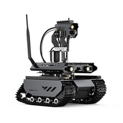
[Tutorial Navigation]
- Jetson 01 Introduction to JupyterLab And Robotics Basics
- Introduction to Robotics Basics
- Basic Tutorial on Interactive Development Using JupyterLab
- Jetson 02 Python Chassis Motion Control
- Python Chassis Motion Control
- Control Mechanism Overview
- Design Advantages
- Main Program (app.py)
- Chassis Control Demo
- Chassis Model Selection
- Chassis Steering Principle
- Jetson 03 Pan-tilt And LED Control
- Pan-tilt Control And LED Control
- Jetson 04 OLED Screen Control
- Jetson 05 Building UI Interfaces in JupyterLab
- Importing Required Libraries
- Creating UI Components
- Defining Event Handling Functions
- Displaying the UI
- Jetson 06 Retrieving Chassis Feedback Information
- How to Retrievie Chassis Feedback Information
- Jetson 07 Controlling Slave Devices with JSON Commands
- Advantages of JSON data format
- A Simple Example of Controlling a Subordinate Device with JSON Commands
- 08 Sub-controller JSON Command Set
- Composition of JSON Commands
- JSON Command Set
- Motion Control Commands
- CMD_SPEED_CTRL
- CMD_PWM_INPUT
- CMD_ROS_CTRL
- CMD_SET_MOTOR_PID
- OLED Display Control Commands
- CMD_OLED_CTRL
- CMD_OLED_DEFAULT
- Module Type
- CMD_MODULE_TYPE
- IMU Related Functions
- Chassis Information Feedback
- WIFI Configuration
- CMD_WIFI_ON_BOOT
- CMD_SET_AP
- CMD_SET_STA
- CMD_WIFI_APSTA
- CMD_WIFI_INFO
- CMD_WIFI_CONFIG_CREATE_BY_STATUS
- CMD_WIFI_CONFIG_CREATE_BY_INPUT
- CMD_WIFI_STOP
- 12V Switch and Gimbal Settings
- CMD_LED_CTRL
- CMD_GIMBAL_CTRL_SIMPLE
- CMD_GIMBAL_CTRL_MOVE
- CMD_GIMBAL_CTRL_STOP
- CMD_GIMBAL_STEADY
- CMD_GIMBAL_USER_CTRL
- Robotic Arm Control
- CMD_MOVE_INIT
- CMD_SINGLE_JOINT_CTRL
- CMD_JOINTS_RAD_CTRL
- CMD_SINGLE_AXIS_CTRL
- CMD_XYZT_GOAL_CTRL
- CMD_XYZT_DIRECT_CTRL
- CMD_SERVO_RAD_FEEDBACK
- CMD_EOAT_HAND_CTRL
- CMD_EOAT_GRAB_TORQUE
- CMD_SET_JOINT_PID
- CMD_RESET_PID
- CMD_SET_NEW_X
- CMD_DYNAMIC_ADAPTATION
- Other Settings
- ESP-NOW Related Settings
- CMD_BROADCAST_FOLLOWER
- CMD_GET_MAC_ADDRESS
- CMD_ESP_NOW_ADD_FOLLOWER
- CMD_ESP_NOW_REMOVE_FOLLOWER
- CMD_ESP_NOW_GROUP_CTRL
- CMD_ESP_NOW_SINGLE
- Task File Related Functions
- CMD_SCAN_FILES
- CMD_CREATE_FILE
- CMD_READ_FILE
- CMD_DELETE_FILE
- CMD_APPEND_LINE
- CMD_INSERT_LINE
- CMD_REPLACE_LINE
- Servo Settings
- ESP32 Related Features
- Jetson 09 Automatic Command Execution upon Booting
- 10 Play Audio Files
- Play Audio Files
- 11 Text-to-Speech (TTS)
- Jetson 12 Image Low-Delay Transmission Through Flask
- Jetson 13 Displaying Real-Time Image in Jupyter Lab
- Jetson 14 Time-lapse Photography
- Jetson 15 OpenCV Motion Detection
- Jetson 16 Controlling Photo Capture with Buttons
- Jetson 17 Face Recognition Based on OpenCV
- Jetson 18 Object Recognition Based on DNN (Deep Neural Network)
- Jetson 19 OpenCV Color Recognition
- Jetson 20 OpenCV Color Tracking
- OpenCV Color Tracking
- Jetson 21 Line Following Autonomous Driving with OpenCV
- Jetson 22 Gesture Recognition Based on MediaPipe
- Jetson 23 Face Recognition Based on MediaPipe
- Jetson 24 Pose Detection with MediaPipe
- Jetson 25 Simple Web-Based Application
- Jetson 26 Introduction to Main Program Architecture
- Introduction to Main Program Architecture
- File Structure and Functionality Introduction
- Install Script
- Auto-running Demo
- Update Project
- Open-source Project
- 27 YAML Configuration File Settings
- What is YAML?
- Advantages of YAML
- Human Readability
- Ease of Writing and Editing
- Support for Complex Data Structures
- Extensibility
- Language Independence
- Configuration File config.yaml for this Product
- 28 Crontab Automatic Startup Script
- Crontab File
- Crontab Format
- Usage
- Comparison
- Advantages of Crontab
- Advantages of Services
- Special Advantages of Crontab in this Product
- 29 Custom Command Line Functionality
- 30 Web Command Line Application
- Sending Information via ESP-NOW
- Add Broadcast MAC Address to Peer
- Add Specific MAC Address to Peer
- Remove Broadcast MAC Address from Peer
- Remove Specific MAC Address from Peer
- Broadcast Sending (Broadcast MAC should be added to peer before first use)
- Unicast Sending (Target MAC should be added to peer before first use)
- Multicast Sending (Target MAC should be added to peer before first use, multiple targets can be added, and cannot include broadcast MAC address: FF:FF:FF:FF:FF:FF)
- Audio Playback
- Text-to-Speech (TTS, initialization takes longer for the first use)
- Set Volume Level (Range between 0 and 1.0)
- Play Audio File from the 'sounds' Directory (.mp3 .wav formats, can play files from other directories)
- Chassis
- Send JSON Commands Directly to Chassis, Specific commands should be referred to related WIKI
- Enable Displaying Information from Chassis on Screen
- Disable Displaying Information from Chassis on Screen
- Default Display Time for Command Line/ESP-NOW Information is 10 seconds
- OpenCV
- Support