




- sales/support
Google Chat:---
- sales
+86-0755-88291180
- sales01
sales@spotpear.com
- sales02
dragon_manager@163.com
- support
tech-support@spotpear.com
- CEO-Complaints
zhoujie@spotpear.com
- Only Tech-Support
WhatsApp:13246739196
- Purchase/Shipping/Refund
WhatsApp:13424403025
- HOME
- >
- ARTICLES
- >
- Common Moudle
- >
- WIFI
Core2021-HF User Guide
Features
- Uses the fourth‑generation LoRa® multi‑band transceiver LR2021 from Semtech
- Supports Sub‑GHz (410 ~ 510MHz / 850 ~ 930MHz), the 2.4 GHz ISM band, and the 1.5 ~ 2.5 GHz licensed band
- Connects to the cloud via LoRa or LoRaWAN protocols through a gateway, building a low‑power wide‑area network
- Compatible with multiple protocols such as LoRa, FLRC, FSK, BLE, and ZigBee
- SPI control, supports mainstream MCU platforms for easy integration and porting
- Suitable for IoT applications such as industrial telemetry, smart homes, environmental monitoring, and remote data acquisition
- Provides comprehensive supporting documentation and manuals (example programs and user manuals for ESP32, Raspberry Pi, Arduino, STM32, and Raspberry Pi Pico, etc.)
Specifications
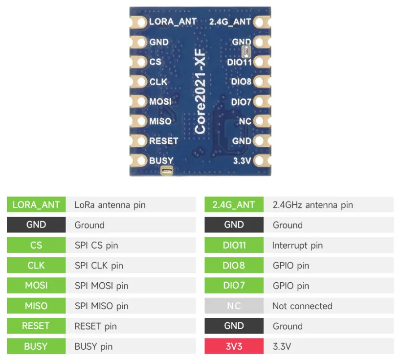
Interface Description
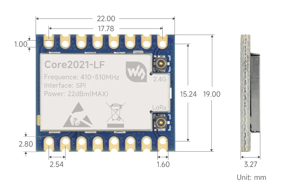
Dimensions
Working with ESP32S3
This chapter contains the following sections. Please read as needed:
Setting Up Development Environment
1. Installation and Configuration
- For setting up the ESP32S3 environment and basic usage, please refer to the following links:
- Once the environment is set up, you can connect the LoRa module and download the example programs
Hardware Connection
Connect according to the table below.
| Core2021-XF | ESP32S3 |
|---|---|
| CLK | 40 |
| MISO | 46 |
| MOSI | 45 |
| CS | 42 |
| DIO11 | 38 |
| RESET | 39 |
| BUSY | 41 |
Example
- ESP32S3 example programs are located in the
core2021-xf\examples\esp32s3directory of the example package. - Examples 01, 02, and 03 require two Core2021-XF modules: one for transmission and one for reception.
| Example | Basic Description | Dependency Library |
|---|---|---|
| 01_lr2021_tx | LR2021 Transmit | RadioLib |
| 02_lr2021_rx | LR2021 Receive | RadioLib |
| 03_lr2021_pingpong | LR2021 Ping‑Pong | RadioLib |
| 04_lr2021_tx_cw | LR2021 CW Mode Transmit | RadioLib |
| 05_lr2021_LoRaWAN | LoRaWAN | RadioLib |
Run Arduino ESP32 Example
- Navigate to
core2021-xf\examples\esp32s3\arduinoand select the example program you wish to test. - Select the development board:
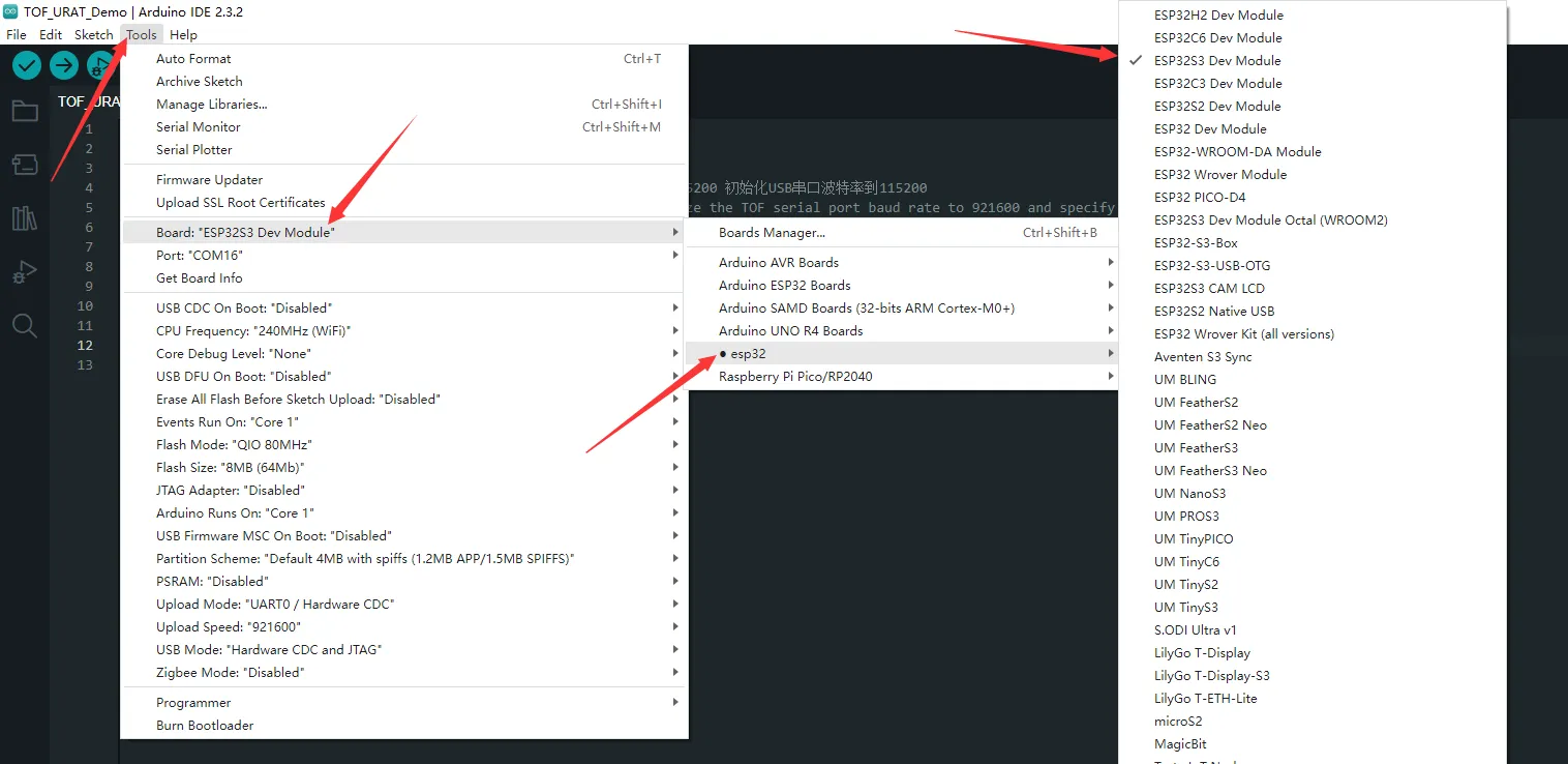
- Select the port for the ESP32S3, then compile and upload.
- After the upload is completed, open the serial port monitor, and the relevant information will be output.
01_lr2021_tx
Example Description
- Based on the ESP32S3 + Core2021-XF module, implements periodic LoRa packet transmission using interrupts.
- Custom SPI pins (CLK/MOSI/MISO) to match the ESP32S3 hardware design.
- Uses non‑blocking transmission, does not occupy CPU resources in the main loop.
- After each packet is sent, automatically delays 1 second before sending the next packet.
- Supports string data transmission, with a built‑in packet sequence number for easy debugging.
Code Analysis
SPI.begin(...): Initializes ESP32S3 hardware SPI pins with custom CLK/MOSI/MISO.radio.irqDioNum = 11: Configures the LR2021 interrupt mapping pin; must be set before initialization.radio.XTAL = true: Enables the external crystal oscillator to ensure frequency accuracy.setFlag(void): Interrupt callback function triggered automatically after the module finishes transmission, sets a transmission‑complete flag.radio.setPacketSentAction(setFlag): Binds the transmission‑complete interrupt function.radio.startTransmit("content"): Starts asynchronous LoRa transmission (supports string / byte array).radio.finishTransmit(): Cleanup after transmission, turns off the transmit circuit and resets the module state.loop()main logic: Check transmission‑complete flag → print status → delay → send next packet with sequence number.
Operation Result
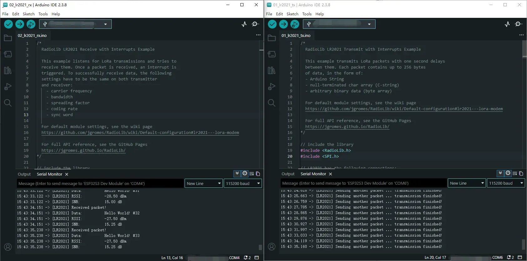
After compiling and uploading, open the serial monitor to see logs indicating transmission completion, as shown below (in combination with 02_lr2021_rx):
02_lr2021_rx
Example Description
- Based on the ESP32S3 + Core2021-XF module, implements wireless LoRa packet reception using interrupts.
- Custom hardware SPI pins to match the ESP32S3 hardware design.
- Uses non‑blocking listening mode; the module automatically waits for data without consuming CPU resources.
- After successful reception, automatically parses the data and prints the packet content, RSSI, and SNR.
- The same frequency, spreading factor, bandwidth, and coding rate must be configured on both the transmitter and receiver for successful communication.
Code Analysis
SPI.begin(...): Initializes ESP32S3 hardware SPI with custom CLK/MOSI/MISO pins.radio.irqDioNum = 11: Configures the LR2021 interrupt mapping pin; must be set before initialization.radio.XTAL = true: Enables the external crystal oscillator to ensure frequency accuracy and improve reception stability.setFlag(void): Interrupt callback function triggered automatically after a complete packet is received.radio.setPacketReceivedAction(setFlag): Binds the reception‑complete interrupt service function.radio.startReceive(): Starts continuous LoRa reception mode, enters a data‑waiting state.radio.readData(str): Reads the received wireless data (supports string parsing).radio.getRSSI()/radio.getSNR(): Retrieves signal quality parameters for debugging and link evaluation.loop()main logic: Check reception‑complete flag → read data → parse and print → continue listening.
Operation Result
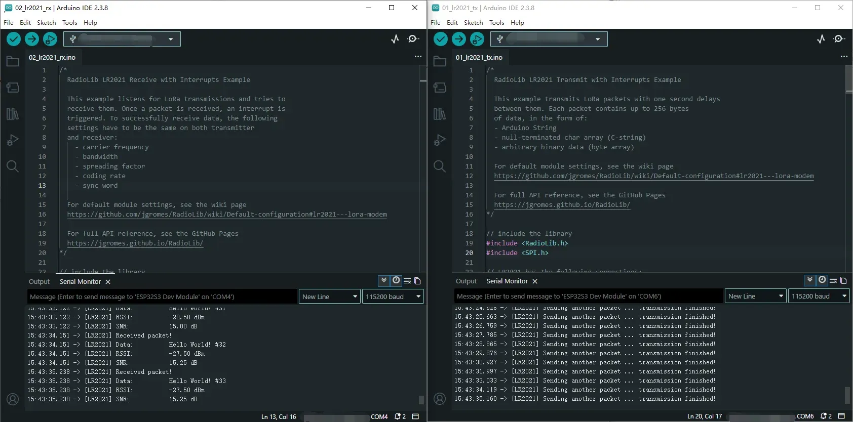
After compiling and uploading, open the serial monitor to see real‑time reception logs including data content, RSSI, and SNR, as shown below (in combination with 01_lr2021_tx):
03_lr2021_pingpong
Example Description
- Based on the ESP32S3 + Core2021-XF module, implements LoRa automatic ping‑pong (question‑answer) two‑way communication.
- Custom hardware SPI pins to match the ESP32S3 hardware design.
- Two modules can send and receive to each other without manual control.
- Enabling
INITIATING_NODEsets the module as the initiator; the other module acts as the responder. - Automatically switches between transmit and receive states, driven by non‑blocking interrupts.
Code Analysis
SPI.begin(...): Initializes ESP32S3 hardware SPI with custom CLK/MOSI/MISO pins.radio.irqDioNum = 11: Configures the LR2021 interrupt mapping pin; must be set before initialization.radio.XTAL = true: Enables the external crystal oscillator to ensure communication frequency accuracy.setFlag(void): General interrupt callback, triggered on either transmit or receive completion.radio.setIrqAction(setFlag): Binds the shared transmit/receive interrupt function.INITIATING_NODEmacro: Used to distinguish the initiating node.radio.startTransmit(): Starts packet transmission.radio.startReceive(): Switches the module to listening (receive) mode.radio.readData(str): Reads the received LoRa packet.loop()main logic: Transmit complete → enter receive; receive complete → delay reply → transmit again.
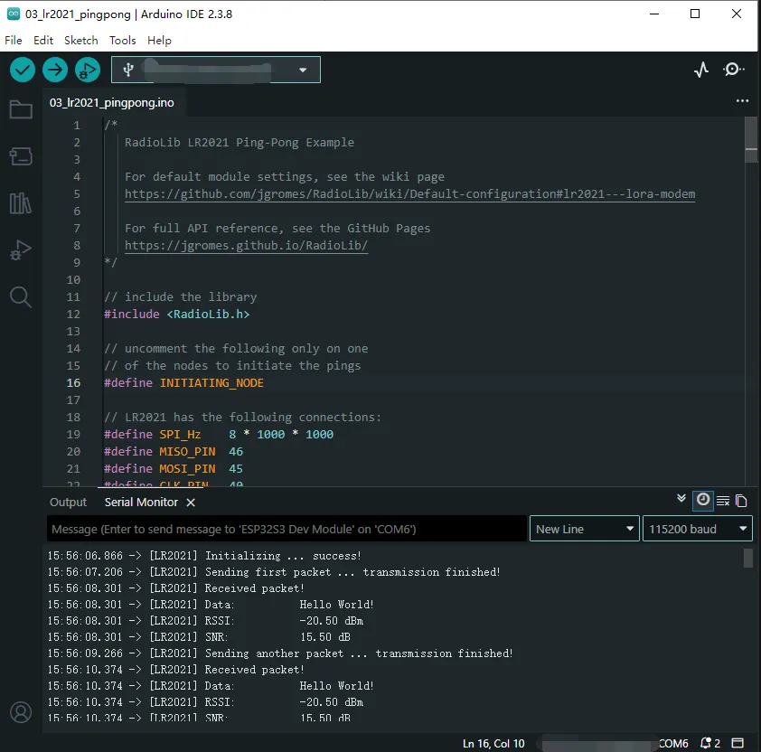
Operation Result
- Flash the program onto two modules, enabling the
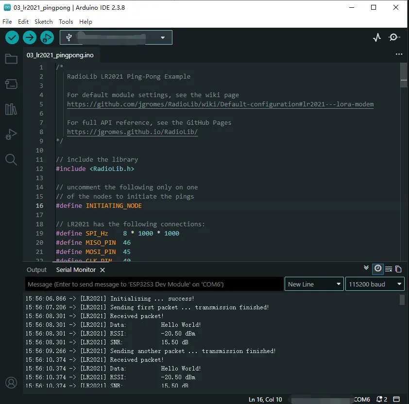
INITIATING_NODEmacro on one of them. - After power‑on, they automatically send and receive to each other; the serial monitor prints the transmit/receive status, data, RSSI, and SNR, as shown below:
04_lr2021_tx_cw
Example Description
- Based on the ESP32S3 + Core2021-XF module, implements LoRa continuous wave (CW) / direct transmit.
- Custom SPI pins to match the ESP32S3 hardware design.
- Outputs a fixed‑frequency carrier signal without packet formatting, used for band testing, signal detection, and instrument calibration.
- Fixed frequency 868 MHz, transmit power 22 dBm.
- Upon power‑up, transmits continuously with no additional logic.
Code Analysis
SPI.begin(...): Initializes ESP32S3 hardware SPI with custom CLK/MOSI/MISO pins.radio.XTAL = true: Enables the external crystal oscillator to ensure carrier frequency accuracy.OUT_HZ 868000000UL: Defines the direct transmit frequency (868 MHz); can be modified.radio.setOutputPower(22): Sets the transmit power to 22 dBm.radio.transmitDirect(OUT_HZ): Enters continuous direct transmission mode, outputting a fixed‑frequency carrier.loop(): No business logic; the carrier continues to transmit without program intervention.
Operation Result
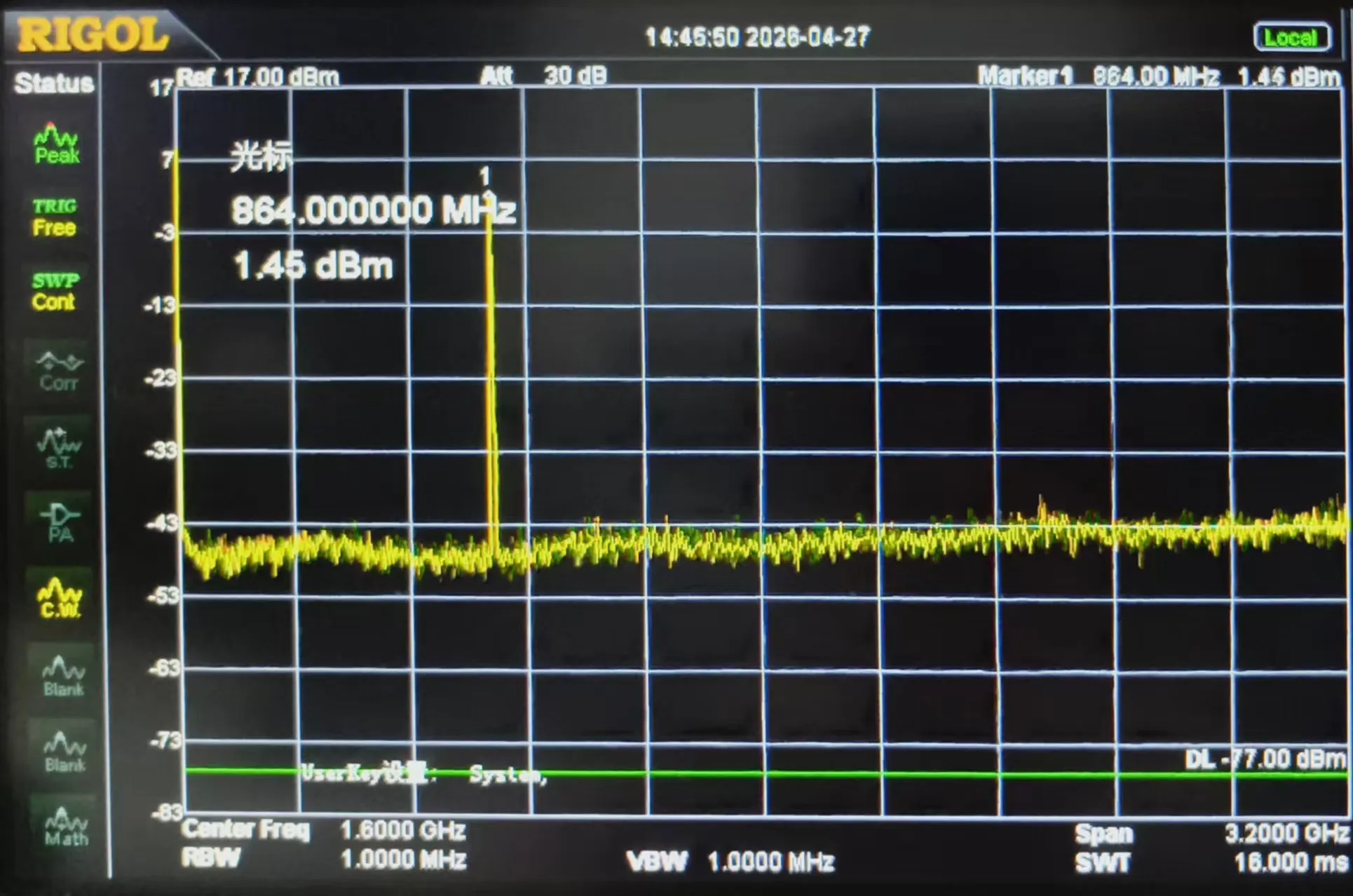
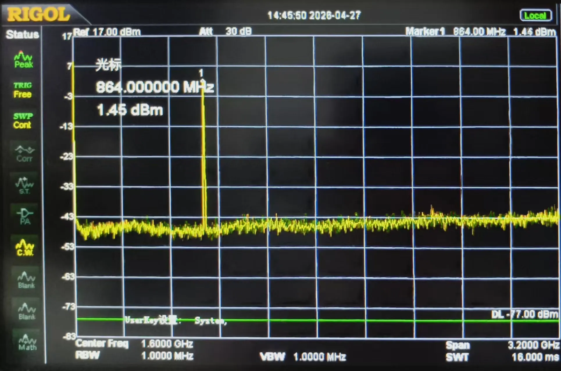
After flashing, the module immediately outputs a fixed‑frequency carrier signal.
The serial port prints initialization and transmission start status; a spectrum analyzer or receiving module can detect the continuous RF signal, as shown below:
05_lr2021_LoRaWAN
Example Description
- Based on the ESP32S3 + Core2021-XF module, implements LoRaWAN OTAA join + uplink/downlink communication.
- Custom SPI pins to match the ESP32S3 hardware design.
- Uses NVS flash to store session information, allowing fast reconnection after power‑off reboot without re‑joining.
- Periodically uploads random data (default every 5 minutes) and automatically listens for server downlink messages.
- Supports printing downlink data in HEX/ASCII formats for easy debugging and link verification.
Code Analysis
SPI.begin(...): Initializes ESP32S3 hardware SPI with custom CLK/MOSI/MISO pins.radio.irqDioNum = 11: Configures the LR2021 interrupt mapping; must be set before initialization.radio.XTAL = true: Enables the external crystal oscillator to ensure LoRaWAN frequency accuracy.prefs.begin(...): Initializes the ESP32 NVS partition for storing LoRaWAN session information.restoreLoRaWANState(): Restores session information from NVS for fast reconnection.node.beginOTAA()/node.activateOTAA(): OTAA join functions.saveLoRaWANState(): Saves session information to NVS after successful join.node.sendReceive(): Sends uplink data and automatically listens for server downlink messages.printHex / printAscii: Formats and prints received data.
Operation Result
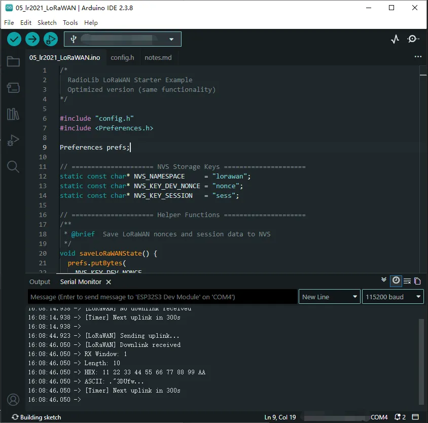
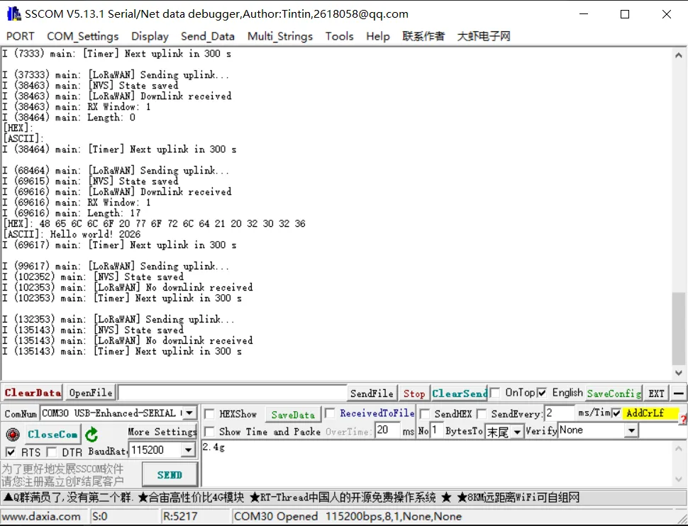
After flashing, the module automatically completes OTAA join, periodically reports data, and listens for downlink messages.
The serial port prints join status, uplink/downlink messages, signal quality, etc., as shown below:
Run ESP-IDF Example
01_lr2021_tx
Example Description
- Based on the native ESP‑IDF framework + ESP32S3 + Core2021-XF module, implements periodic LoRa packet transmission using interrupts.
- Includes a dedicated hardware abstraction layer
EspHal.hthat perfectly adapts to the ESP‑IDF environment. - Custom SPI pin configuration supporting hardware SPI2 bus.
- Uses interrupt‑driven non‑blocking transmission, automatically sending one packet with sequence number every second.
- Log output uses the native ESP‑IDF
ESP_LOGfor stable and reliable operation.
Core Files
EspHal.h: ESP‑IDF hardware abstraction layer providing low‑level implementations for GPIO, SPI, delays, and interrupts (common to all examples).main.cpp: LoRa transmit main program.
Code Analysis
EspHal* hal = new EspHal(...): Initializes the ESP‑IDF hardware abstraction layer.radio.irqDioNum = 11: Configures the LR2021 interrupt mapping pin.radio.XTAL = true: Enables the external crystal oscillator to ensure frequency accuracy.setFlag(void): Transmit‑complete interrupt callback function.radio.setPacketSentAction(setFlag): Binds the transmit‑complete interrupt.radio.startTransmit(...): Starts asynchronous LoRa transmission.radio.finishTransmit(): Turns off the RF circuit after transmission to ensure low‑power stability.
Operation Result
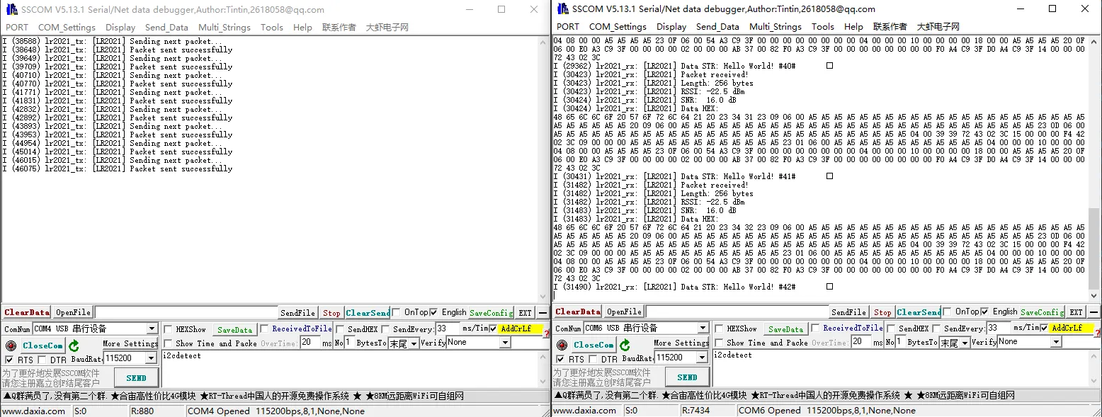
- After compiling and flashing, the serial port prints the transmission status and packet sequence number in real time.
- Can be paired with 02_lr2021_rx to complete one‑way LoRa wireless communication in the ESP‑IDF environment.
02_lr2021_rx
Example Description
- Based on the native ESP‑IDF framework + ESP32S3 + Core2021-XF module, implements wireless LoRa packet reception using interrupts.
- Relies on the generic hardware abstraction layer
EspHal.hfor perfect adaptation to the ESP‑IDF environment. - Custom SPI pin configuration supporting hardware SPI2 bus.
- Interrupt‑driven non‑blocking listening, receiving data in real time.
- After reception, automatically prints: length, RSSI, SNR, HEX format, and string format.
Core Files
EspHal.h: Low‑level hardware abstraction (common to all examples).main.cpp: LoRa receive main program.
Code Analysis
EspHal* hal: Initializes ESP‑IDF hardware abstraction (GPIO/SPI/interrupts).radio.irqDioNum = 11: Configures the LR2021 interrupt mapping.radio.XTAL = true: Enables the external crystal oscillator to ensure receive frequency accuracy.setFlag(void): Receive‑complete interrupt callback.radio.setPacketReceivedAction(setFlag): Binds the receive‑complete interrupt.radio.startReceive(): Starts continuous LoRa listening.radio.readData(): Reads and parses the received packet.- Automatically restarts listening, enabling continuous reception.
Operation Result
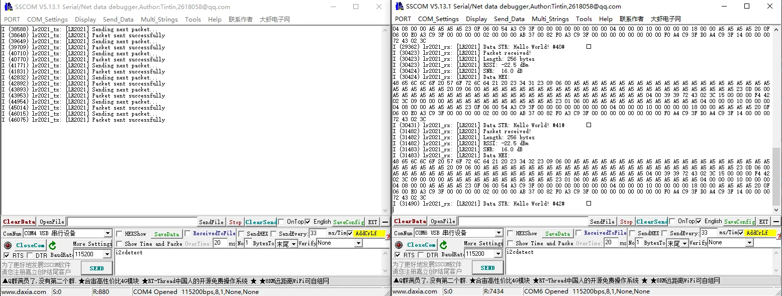
- After flashing, the module enters listening mode and prints data as soon as it is received.
- Can be paired with 01_lr2021_tx to complete full wireless communication.
03_lr2021_pingpong
Example Description
- Based on the native ESP‑IDF framework + ESP32S3 + Core2021-XF module, implements automatic LoRa ping‑pong bidirectional communication (question‑answer).
- Relies on the generic hardware abstraction layer
EspHal.hfor perfect adaptation to the ESP‑IDF environment. - Custom SPI pin configuration supporting hardware SPI2 bus.
- Uses interrupt‑driven non‑blocking mechanisms, automatically switching between transmit and receive states.
- Supports distinguishing the initiating node from the listening node via a macro; upon power‑up they automatically send and receive to each other.
- Upon receiving a packet, automatically prints the payload content, RSSI, and SNR for easy link debugging.
Core Files
EspHal.h: Low‑level hardware abstraction (common to all ESP‑IDF examples).main.cpp: LoRa ping‑pong bidirectional communication application.
Code Analysis
EspHal* hal: Instantiates the ESP‑IDF hardware abstraction layer (SPI, GPIO, delays, interrupts).radio.irqDioNum = 11: Configures the LR2021 interrupt mapping pin.radio.XTAL = true: Enables the external crystal oscillator to ensure LoRa frequency accuracy.setFlag(void): Common interrupt callback for both transmit and receive events.radio.setIrqAction(setFlag): Binds the module interrupt callback.INITIATING_NODE: Macro switch that defines the device as the active packet‑sending node.radio.startTransmit()/radio.startReceive(): The program automatically switches between transmit and listen modes.radio.readData(): Parses received packets and prints text and signal parameters.- Closed‑loop logic: after sending, switch to receive; after receiving, delay and automatically reply, continuing the ping‑pong cycle.
Operation Result
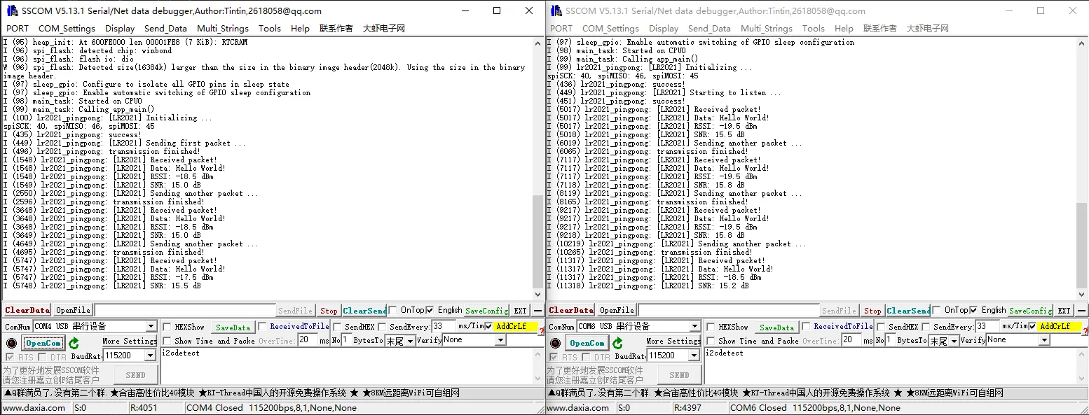
- After flashing both ESP32s, they automatically establish a bidirectional LoRa link and exchange data continuously.
- The serial terminal prints initialization status, transmission/reception results, RSSI, and SNR in real time.
04_lr2021_tx_cw
Example Description
- Based on the native ESP‑IDF framework + ESP32S3 + Core2021-XF module, implements fixed‑frequency continuous wave (CW) transmission.
- Relies on the generic hardware abstraction layer
EspHal.hfor perfect adaptation to the ESP‑IDF environment. - Custom SPI pin configuration supporting hardware SPI2 bus.
- Outputs a clean, packet‑free continuous RF signal, suitable for instrument calibration, band testing, and signal strength detection.
- Transmission frequency: 868 MHz, transmit power: 22 dBm; continuously transmits after power‑up without interruption.
Core Files
EspHal.h: Low‑level hardware abstraction (common to all ESP‑IDF examples).04_lr2021_direct_transmit.c: LoRa carrier transmission main program.
Code Analysis
EspHal* hal: Initializes ESP‑IDF hardware abstraction (SPI, GPIO, delays, interrupts).radio.irqDioNum = 11: Configures the LR2021 interrupt mapping pin.radio.XTAL = true: Enables the external crystal oscillator to ensure carrier frequency accuracy.OUT_HZ 868000000UL: Defines the continuous transmit frequency (868 MHz).radio.setOutputPower(22): Sets the transmit power to 22 dBm.radio.transmitDirect(OUT_HZ): Enters direct carrier transmission mode, starting continuous transmission.
Operation Result
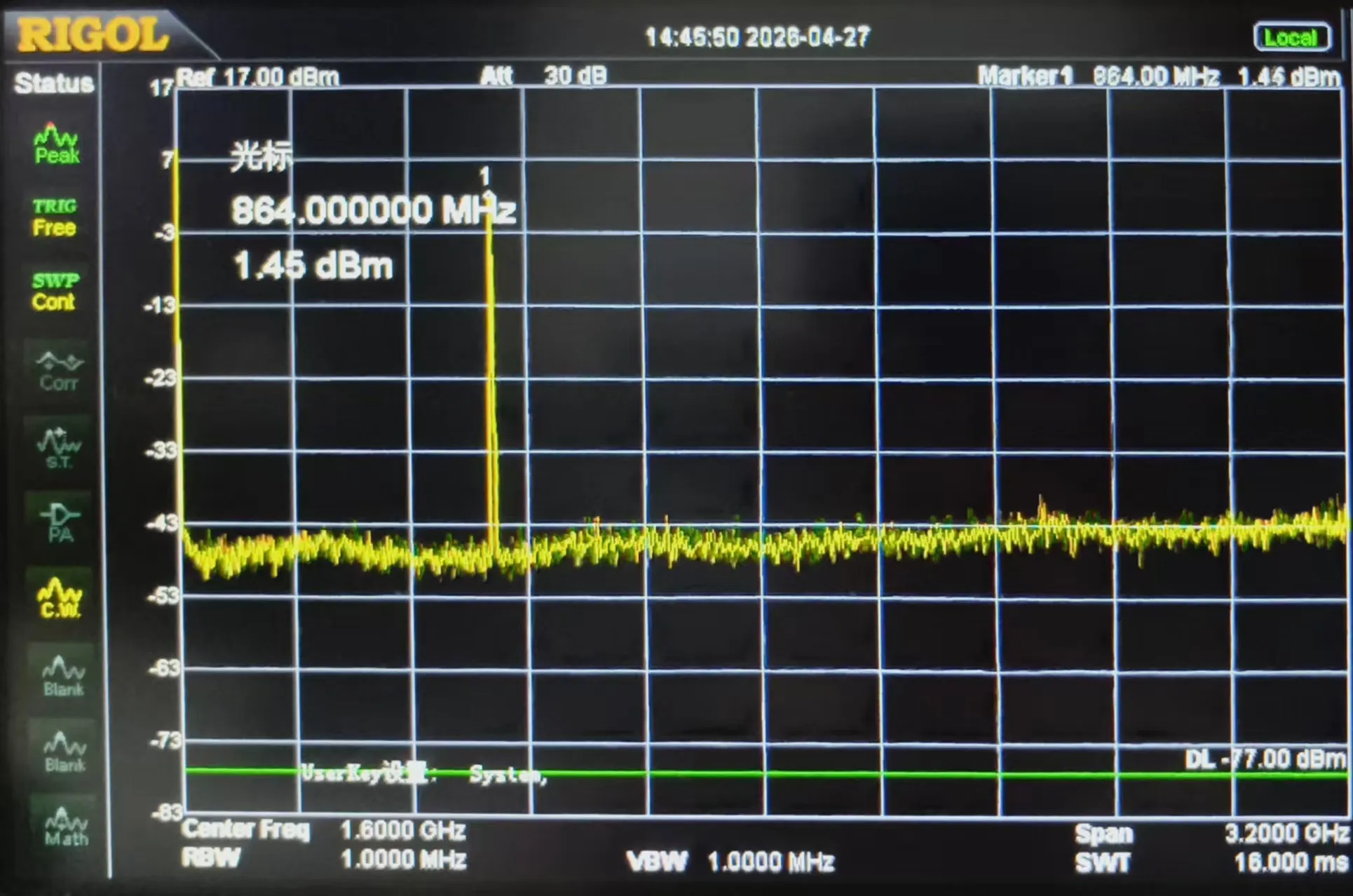
- After flashing, the module immediately outputs a stable continuous RF signal.
- A spectrum analyzer or receiving device can detect the stable carrier for band testing and calibration.
05_lr2021_LoRaWAN
Example Description
- Based on the native ESP‑IDF framework + ESP32S3 + Core2021-XF module, implements LoRaWAN OTAA join + periodic uplink + downlink reception.
- Relies on the generic hardware abstraction layer
EspHal.h; runs independently in the pure ESP‑IDF environment. - Uses NVS flash to persistently store session information, allowing fast recovery after power‑off without re‑joining.
- Automatically reports random test data, supports parsing and printing of server downlink data.
- Full log output: join status, signal quality, uplink/downlink data, session save records.
Core Files
EspHal.h: Low‑level hardware abstraction (common to all ESP‑IDF examples).05_lr2021_lorawan_otaa.c: LoRaWAN OTAA communication main program.
Code Analysis
EspHal* hal: Initializes ESP‑IDF hardware abstraction (SPI, GPIO, delays, interrupts).radio.irqDioNum = 11: Configures the LR2021 interrupt mapping pin.radio.XTAL = true: Enables the external crystal oscillator to ensure LoRa frequency accuracy.nvs_flash_init(): Enables NVS storage for saving LoRaWAN session information.restoreLoRaWANState(): Recovers session from flash for fast reconnection.node.beginOTAA()/node.activateOTAA(): OTAA join key functions.node.sendReceive(): Sends uplink data and listens for server downlink messages.printHex / printAscii: Formats and prints downlink data.
Operation Result
- After the program runs, it automatically completes OTAA join, periodically reports data, and receives downlink messages from the server.
- The serial terminal prints join status, upload records, signal quality, and downlink content in real time.
Working with Raspberry Pi Pico
This chapter contains the following sections. Please read as needed:
Setting Up Development Environment
1. Installation and Configuration
- For setting up the Raspberry Pi Pico environment and basic usage, please refer to the following links:
- After setting up the environment, connect the sensor and download the example package.
Hardware Connection
Connect according to the table below.
| Core2021-XF | Raspberry Pi Pico/Pico2 |
|---|---|
| CLK | 10 |
| MISO | 11 |
| MOSI | 12 |
| CS | 13 |
| DIO11 | 15 |
| RESET | 5 |
| BUSY | 14 |
Example
- Raspberry Pi Pico example programs are located in the
core2021-xf\examples\picodirectory of the example package. - Examples 01, 02, and 03 require two Core2021-XF modules: one for transmission and one for reception.
| Example | Basic Description | Dependency Library |
|---|---|---|
| 01_lr2021_tx | LR2021 Transmit | RadioLib |
| 02_lr2021_rx | LR2021 Receive | RadioLib |
| 03_lr2021_pingpong | LR2021 Ping‑Pong | RadioLib |
| 04_lr2021_tx_cw | LR2021 CW Mode Transmit | RadioLib |
| 05_lr2021_LoRaWAN | LoRaWAN | RadioLib |
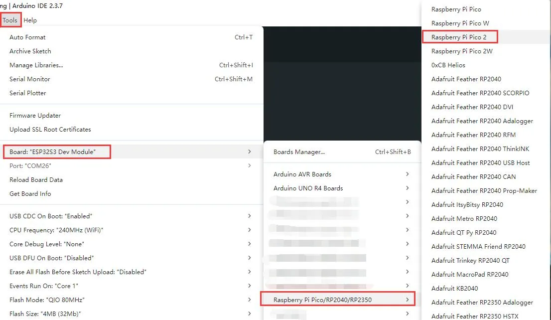
Arduino Pico Examples
Navigate to
core2021-xf\examples\pico\arduinoand select the example program you wish to test.Select the chip model and port.
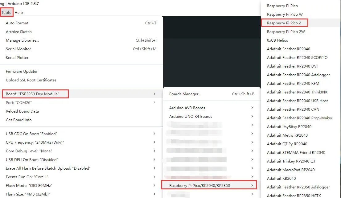
After uploading, open the serial port monitor, and the relevant information will be output.
01_lr2021_tx_arduino
Example Description
- Based on the Raspberry Pi Pico + Core2021-XF module, implements periodic LoRa packet transmission using interrupts.
- Uses the Pico/Pico2 hardware SPI1 port with custom SPI pin mapping.
- Uses non‑blocking transmission, does not occupy CPU resources in the main loop.
- After each packet is sent, automatically delays 1 second before sending the next packet.
- Supports string data transmission, with a built‑in packet sequence number for easy debugging.
Code Analysis
SPI1.setSCK / setRX / setTX: Remaps pins for RP2040 hardware SPI1.SPI1.begin(): Starts the Raspberry Pi Pico hardware SPI1.radio.irqDioNum = 11: Configures the LR2021 interrupt mapping pin; must be set before initialization.radio.XTAL = true: Enables the external crystal oscillator to ensure frequency accuracy.setFlag(void): Interrupt callback function triggered automatically after the module finishes transmission, sets a transmission‑complete flag.radio.setPacketSentAction(setFlag): Binds the transmission‑complete interrupt function.radio.startTransmit("content"): Starts asynchronous LoRa transmission (supports string / byte array).radio.finishTransmit(): Cleanup after transmission, turns off the transmit circuit and resets the module state.loop()main logic: Check transmission‑complete flag → print status → delay → send next packet with sequence number.
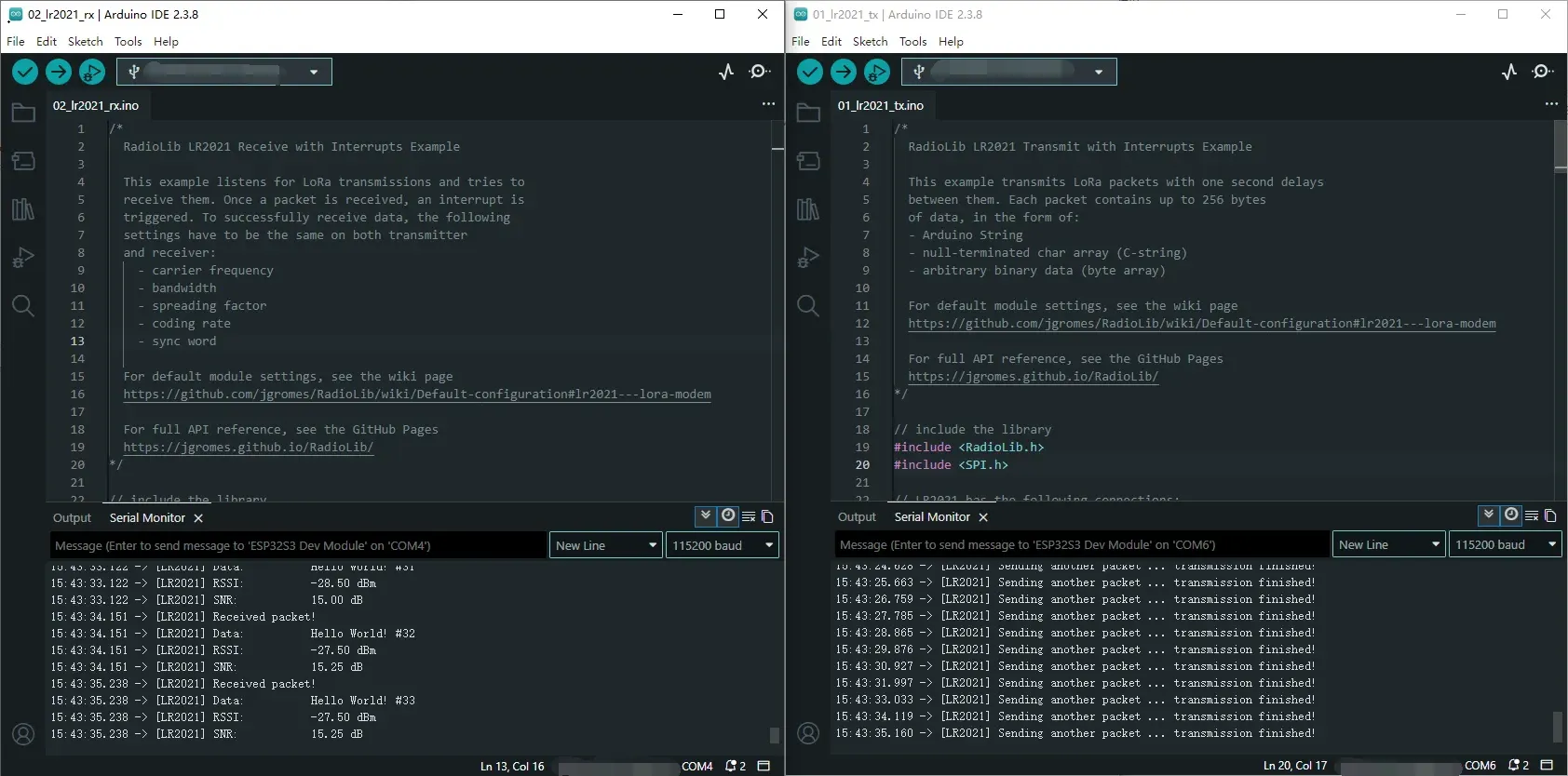
Operation Result
After compiling and uploading, open the serial monitor to see logs indicating transmission completion, as shown below (in combination with 02_lr2021_rx):
02_lr2021_rx_arduino
Example Description
- Based on the Raspberry Pi Pico + Core2021-XF module, implements wireless LoRa packet reception using interrupts.
- Uses the Pico/Pico2 hardware SPI1 port with custom pin mapping.
- Uses non‑blocking listening mode; the module automatically waits for data without consuming CPU resources.
- After successful reception, automatically parses the data and prints the packet content, RSSI, and SNR.
- The same frequency, spreading factor, bandwidth, and coding rate must be configured on both the transmitter and receiver for successful communication.
Code Analysis
SPI1.setSCK / setRX / setTX: Remaps pins for RP2040 hardware SPI1.SPI1.begin(): Initializes the Raspberry Pi Pico hardware SPI1 bus.radio.irqDioNum = 11: Configures the LR2021 interrupt mapping pin; must be set before initialization.radio.XTAL = true: Enables the external crystal oscillator to ensure frequency accuracy and improve reception stability.setFlag(void): Interrupt callback function triggered automatically after a complete packet is received.radio.setPacketReceivedAction(setFlag): Binds the reception‑complete interrupt service function.radio.startReceive(): Starts continuous LoRa reception mode, enters a data‑waiting state.radio.readData(str): Reads the received wireless data (supports string parsing).radio.getRSSI()/radio.getSNR(): Retrieves signal quality parameters for debugging and link evaluation.loop()main logic: Check reception‑complete flag → read data → parse and print → continue listening.
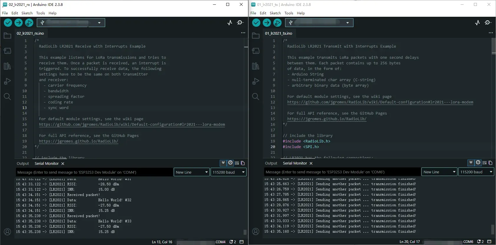
Operation Result
After compiling and uploading, open the serial monitor to see real‑time reception logs including data content, RSSI, and SNR, as shown below (in combination with 01_lr2021_tx):
03_lr2021_pingpong
Example Description
- Based on the Raspberry Pi Pico + Core2021-XF module, implements LoRa automatic ping‑pong (question‑answer) two‑way communication.
- Uses the Pico/Pico2 hardware SPI1 port with arbitrary pin mapping.
- Two modules can send and receive to each other without manual control.
- Enabling
INITIATING_NODEsets the module as the initiator; the other module acts as the responder. - Automatically switches between transmit and receive states, driven by non‑blocking interrupts.
Code Analysis
SPI1.setSCK / setRX / setTX: Remaps pins for Raspberry Pi Pico SPI1.SPI1.begin(): Initializes the hardware SPI1 bus.radio.irqDioNum = 11: Configures the LR2021 interrupt mapping pin; must be set before initialization.radio.XTAL = true: Enables the external crystal oscillator to ensure communication frequency accuracy.setFlag(void): General interrupt callback, triggered on either transmit or receive completion.radio.setIrqAction(setFlag): Binds the shared transmit/receive interrupt function.INITIATING_NODEmacro: Used to distinguish the initiating node.radio.startTransmit(): Starts packet transmission.radio.startReceive(): Switches the module to listening (receive) mode.radio.readData(str): Reads the received LoRa packet.loop()main logic: Transmit complete → enter receive; receive complete → delay reply → transmit again.
Operation Result
- Flash the program onto two modules, enabling the
INITIATING_NODEmacro on one of them. - After power‑on, they automatically send and receive to each other; the serial monitor prints the transmit/receive status, data, RSSI, and SNR, as shown below:
04_lr2021_tx_cw
Example Description
- Based on the Raspberry Pi Pico + Core2021-XF module, implements LoRa continuous wave (CW) / direct transmit.
- Uses the Pico/Pico2 hardware SPI1 port with arbitrary pin mapping.
- Outputs a fixed‑frequency carrier signal without packet formatting, used for band testing, signal detection, and instrument calibration.
- Fixed frequency 868 MHz, transmit power 22 dBm.
- Upon power‑up, transmits continuously with no additional logic.
Code Analysis
SPI1.setSCK / setRX / setTX: Remaps pins for Raspberry Pi Pico SPI1.SPI1.begin(): Initializes the hardware SPI1 bus.radio.XTAL = true: Enables the external crystal oscillator to ensure carrier frequency accuracy.OUT_HZ 868000000UL: Defines the direct transmit frequency (868 MHz); can be modified.radio.setOutputPower(22): Sets the transmit power to 22 dBm.radio.transmitDirect(OUT_HZ): Enters continuous direct transmission mode, outputting a fixed‑frequency carrier.loop(): No business logic; the carrier continues to transmit without program intervention.
Operation Result
After flashing, the module immediately outputs a fixed‑frequency carrier signal.
The serial port prints initialization and transmission start status; a spectrum analyzer or receiving module can detect the continuous RF signal, as shown below:
05_lr2021_LoRaWAN
Example Description
- Based on the Raspberry Pi Pico + Core2021-XF module, implements LoRaWAN OTAA join and uplink/downlink communication.
- Uses EEPROM emulation storage to save session information, allowing fast reconnection after power‑off reboot.
- Custom SPI1 pin mapping fully adapted to Pico/Pico2 hardware design.
- Periodically sends uplink data (default every 5 minutes) and automatically listens for server downlink messages.
- Supports HEX/ASCII formatting of received data for debugging and link verification.
Code Analysis
SPI1.setSCK/setRX/setTX: Remaps pins for RP2040 hardware SPI1.SPI1.begin(): Initializes the Raspberry Pi Pico hardware SPI1 bus.radio.irqDioNum = 11: Configures the LR2021 interrupt mapping pin; must be set before initialization.radio.XTAL = true: Enables the external crystal oscillator to ensure LoRaWAN frequency accuracy.EEPROM.begin(256): Initializes the RP2040 on‑chip Flash to emulate EEPROM.restoreLoRaWANState(): Recovers session information from EEPROM for fast reconnection.node.beginOTAA()/activateOTAA(): OTAA join key functions.saveLoRaWANState(): Saves session information to EEPROM after successful join.node.sendReceive(): Sends uplink data and automatically listens for downlink messages.printHex / printAscii: Formats and prints downlink data.
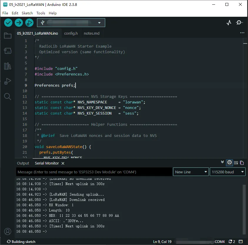
Operation Result
After flashing, the module automatically completes OTAA join, periodically reports data, and listens for downlink messages.
The serial port prints join status, uplink/downlink data, signal quality, etc., as shown below:
C/C++ Examples
Navigate to
core2021-xf\examples\pico\cand select the example program you wish to test.Select the chip model and port.
After uploading, open the serial port monitor, and the relevant information will be output.
01_lr2021_tx
Example Description
- Based on the Raspberry Pi Pico + Core2021-XF module, runs the RadioLib library directly on the Pico in a non‑Arduino environment.
- Uses the hardware SPI1 port with custom SPI pins (SCK=10, MOSI=11, MISO=12).
- Configures LR2021 pins:
- NSS=13, IRQ(DIO0)=15, RESET=5, BUSY=14
- Supports interrupt callbacks, automatically triggered when a packet transmission is complete.
- Non‑blocking transmission; the main loop can check the transmission‑complete flag for further operations.
- Supports sending C‑strings or byte arrays, up to 256 bytes.
- Can continuously send packets with sequence numbers for easy debugging.
Code Analysis
PicoHal* hal = new PicoHal(SPI_PORT, SPI_MISO, SPI_MOSI, SPI_SCK): Creates a Pico hardware abstraction layer instance and binds the SPI port.LR2021 radio = new Module(hal, RFM_NSS, RFM_IRQ, RFM_RST, RFM_BUSY): Initializes the LR2021 module object.radio.irqDioNum = 11: Configures the interrupt mapping pin.radio.XTAL = true: Enables the external crystal oscillator for better frequency accuracy.radio.begin(): Initializes the module and returns an error code.radio.setPacketSentAction(setFlag): Binds the transmission‑complete callback functionsetFlag().radio.setFrequency(868.0),setOutputPower(22),setBandwidth(125.0),setSpreadingFactor(7),setCodingRate(5),setSyncWord(...),setPreambleLength(8): Configures LoRa parameters.radio.startTransmit("Hello World!"): Starts the first packet transmission.setFlag(): SetstransmittedFlag = truewhen transmission is complete; this flag is polled in the main loop.- Main loop
for(;;):- Check
transmittedFlag - Print success/failure status
- Call
radio.finishTransmit()to clean up the transmission - Delay 1 second
- Build a new packet with an incremented sequence number and continue transmitting
- Check
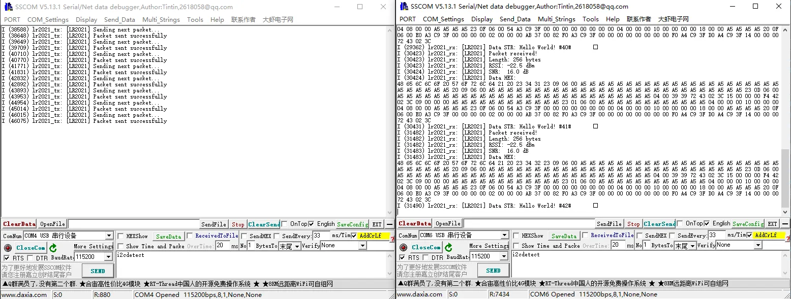
Operation Result
After startup, the serial port prints initialization status (paired with 02_lr2021_rx):
02_lr2021_rx
Example Description
- Based on the Raspberry Pi Pico + Core2021-XF module, runs the RadioLib library directly on the Pico in a non‑Arduino environment to receive data.
- Uses the hardware SPI1 port with custom SPI pins (SCK=10, MOSI=11, MISO=12).
- Configures LR2021 pins:
- NSS=13, IRQ(DIO0)=15, RESET=5, BUSY=14
- Supports interrupt callbacks, automatically triggered when a packet is received.
- Continuous listening mode, automatically re‑enters receive state after each packet.
- Received data can be printed in HEX format or as a string.
Code Analysis
PicoHal* hal = new PicoHal(SPI_PORT, SPI_MISO, SPI_MOSI, SPI_SCK): Creates a Pico hardware abstraction layer instance and binds the SPI port.LR2021 radio = new Module(hal, RFM_NSS, RFM_IRQ, RFM_RST, RFM_BUSY): Initializes the LR2021 module object.radio.irqDioNum = 11: Configures the interrupt mapping pin.radio.XTAL = true: Enables the external crystal oscillator for better frequency accuracy.radio.begin(): Initializes the module and returns an error code.radio.setPacketSentAction(setFlag): Binds the transmission‑complete callback functionsetFlag().radio.setFrequency(868.0),setOutputPower(22),setBandwidth(125.0),setSpreadingFactor(7),setCodingRate(5),setSyncWord(...),setPreambleLength(8): Configures LoRa parameters.radio.startReceive(): Starts receive mode and enters listening state.setFlag(): SetsreceivedFlag = truewhen a packet is received; this flag is polled in the main loop.- Main loop
for(;;):- Check
receivedFlag - Read packet length
radio.getPacketLength()and callradio.readData(rxBuf, len) - Based on the return status, print:
- On success: packet length, RSSI, SNR, HEX dump, and string content
- On CRC error: indicate CRC error
- On other errors: print error code
- Automatically re‑enter receive mode
radio.startReceive() - Delay 10 ms to avoid excessive CPU usage
- Check
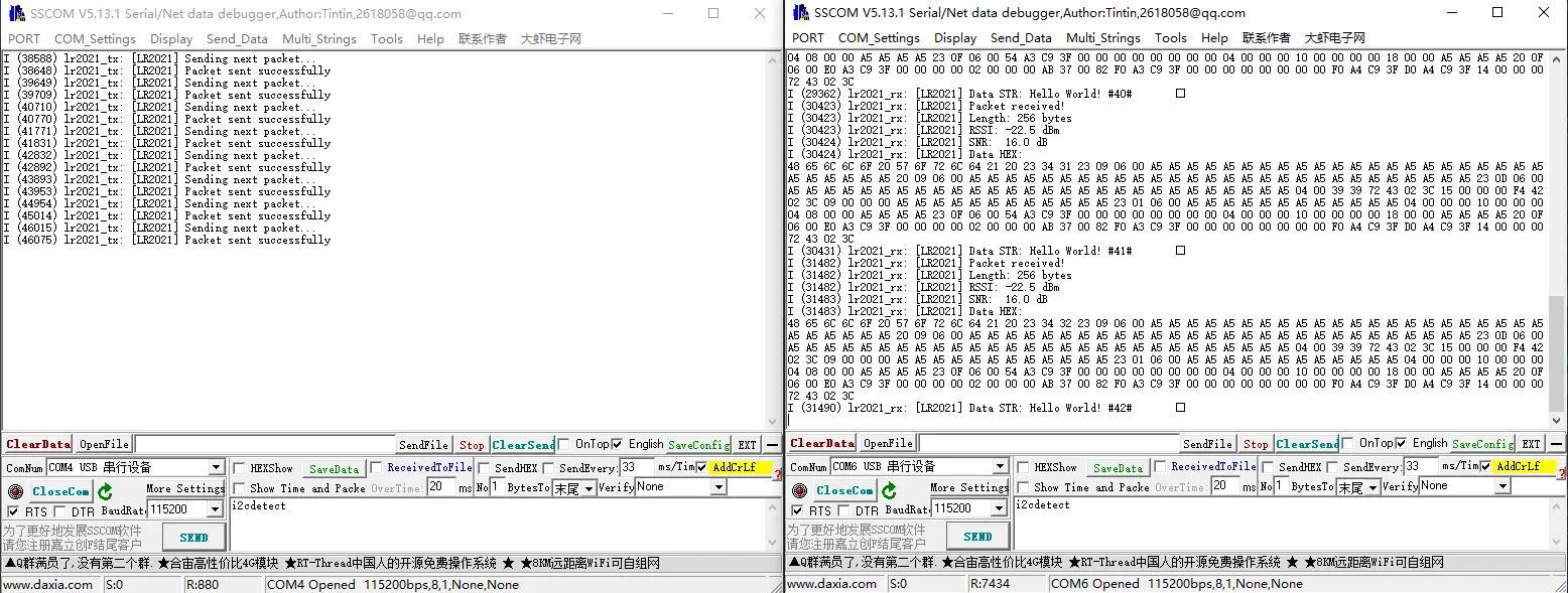
Operation Result
After startup, the serial port prints initialization status (paired with 01_lr2021_tx):
03_lr2021_pingpong
Example Description
- Based on the Raspberry Pi Pico + Core2021-XF module, implements LoRa automatic ping‑pong (question‑answer) two‑way communication.
- Uses the hardware SPI1 port with custom SPI pins (SCK=10, MOSI=11, MISO=12).
- Configures LR2021 pins:
- NSS=13, IRQ(DIO0)=15, RESET=5, BUSY=14
- Supports interrupt callbacks, triggered when a transmission or reception is complete.
- Automatically switches between transmit and receive states without manual intervention.
- The first transmission is controlled by the
#define INITIATING_NODEmacro; the other module automatically enters receive mode. - Supports sending and receiving string data continuously, and prints RSSI/SNR.
Code Analysis
PicoHal* hal = new PicoHal(SPI_PORT, SPI_MISO, SPI_MOSI, SPI_SCK): Creates a Pico hardware abstraction layer instance and binds the SPI port.LR2021 radio = new Module(hal, RFM_NSS, RFM_IRQ, RFM_RST, RFM_BUSY): Initializes the LR2021 module object.radio.irqDioNum = 11: Configures the interrupt mapping pin.radio.XTAL = true: Enables the external crystal oscillator for better frequency accuracy.radio.begin(): Initializes the module and returns an error code.radio.setPacketSentAction(setFlag): Binds the transmit/receive complete callback function.- The macro
INITIATING_NODEdetermines whether the node first sends data. - Main loop
for(;;):- Check the
operationDoneflag. - If transmission is complete:
- Print transmission status
- Switch to receive mode
radio.startReceive()
- If reception is complete:
- Read the packet
radio.readData(rxBuffer, rxLen) - Print the received string, RSSI, SNR
- Delay 1 second, then send again
- Read the packet
- Delay 5 ms at the end of each iteration to avoid high CPU usage
- Check the
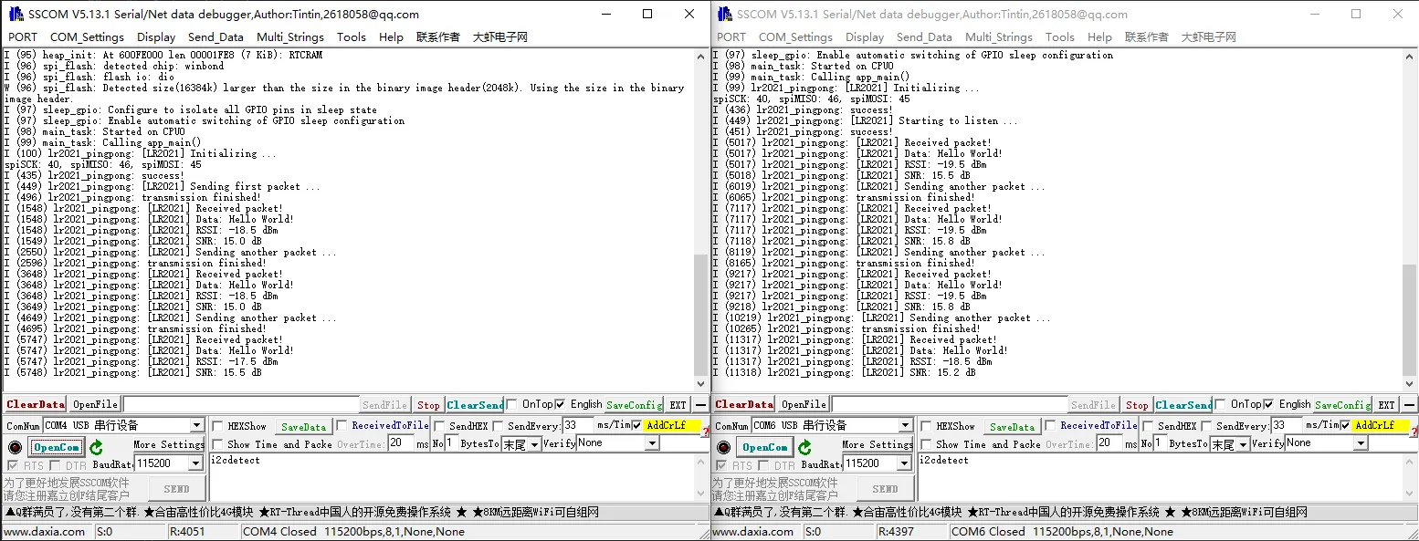
Operation Result
- Two modules are flashed separately; one defines
INITIATING_NODE. - After power‑up, modules automatically send and receive to each other:
04_lr2021_tx_cw
Example Description
- Based on the Raspberry Pi Pico + Core2021-XF module, implements LoRa continuous wave (CW) / direct transmit.
- Uses the hardware SPI1 port with custom SPI pins (SCK=10, MOSI=11, MISO=12).
- Configures LR2021 pins:
- NSS=13, IRQ(DIO0)=15, RESET=5, BUSY=14
- Outputs a fixed‑frequency carrier signal without packet formatting, used for band testing, signal detection, and instrument calibration.
- Fixed frequency 868 MHz, transmit power 22 dBm.
- Upon power‑up, the module transmits continuously with no additional logic.
Code Analysis
PicoHal* hal = new PicoHal(SPI_PORT, SPI_MISO, SPI_MOSI, SPI_SCK): Creates a Pico hardware abstraction layer instance and binds the SPI port.LR2021 radio = new Module(hal, RFM_NSS, RFM_IRQ, RFM_RST, RFM_BUSY): Initializes the LR2021 module object.radio.irqDioNum = 11: Configures the interrupt mapping pin.radio.XTAL = true: Enables the external crystal oscillator for better frequency accuracy.radio.begin(): Initializes the module and returns an error code.radio.setOutputPower(22): Sets the transmit power to 22 dBm.radio.transmitDirect(OUT_HZ): Enters continuous direct transmission mode, outputting a fixed‑frequency carrier.- The main loop has no business logic; the carrier continues to transmit without program intervention.
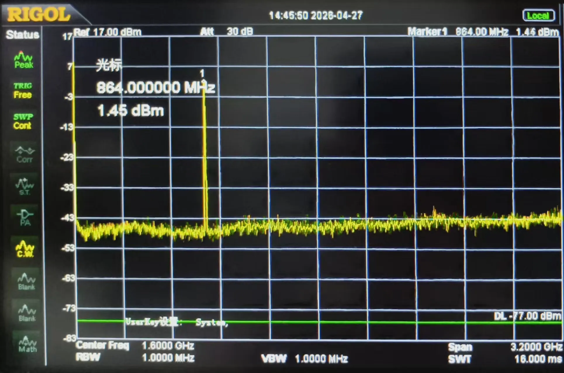
Operation Result
After flashing, the module immediately outputs a fixed‑frequency carrier signal.
The serial port prints initialization and transmission start status; a spectrum analyzer or receiving module can detect the continuous RF signal, as shown below:
05_lr2021_LoRaWAN
Example Description
- Based on the Raspberry Pi Pico + Core2021-XF module, implements LoRaWAN OTAA join and uplink/downlink communication.
- Uses the hardware SPI1 port with custom SPI pins (SCK=10, MOSI=11, MISO=12).
- Supports EEPROM emulation storage, allowing fast reconnection after power‑off reboot.
- Periodically sends uplink data (random 3‑byte payload, default period
uplinkIntervalSeconds). - Automatically receives server downlink messages and prints the data in HEX/ASCII.
- Supports continuous uplink/downlink and automatically saves LoRaWAN session state to prevent DevNonce reuse.
Code Analysis
PicoHal* hal = new PicoHal(SPI_PORT, SPI_MISO, SPI_MOSI, SPI_SCK): Creates a Pico hardware abstraction layer instance and binds the SPI port.LR2021 radio = new Module(hal, RFM_NSS, RFM_IRQ, RFM_RST, RFM_BUSY): Initializes the LR2021 module object.LoRaWANNode node(&radio, &Region, subBand): Creates a LoRaWAN node instance.- Flash EEPROM emulation:
FLASH_TARGET_OFFSET: storage offsetFLASH_EMULATE_EEPROM_SIZE: emulation sizesaveLoRaWANState()/restoreLoRaWANState(): saves/restores LoRaWAN session state
node.beginOTAA(joinEUI, devEUI, nwkKey, appKey): Initializes OTAA parameters.joinLoRaWAN(restored): Attempts to join the network and saves DevNonce/Session.- Uplink/downlink transmission:
node.sendReceive(tx, sizeof(tx), 1, rx, &rxLen): Sends uplink data and receives downlink.- After successful transmission, saves the session to prevent counter rollback.
- Downlink data is printed in HEX/ASCII.
- Loop logic:
- Send a random payload.
- Check if a downlink message is received.
- Save the state.
- Delay for
uplinkIntervalSecondsseconds before the next transmission.
Operation Result
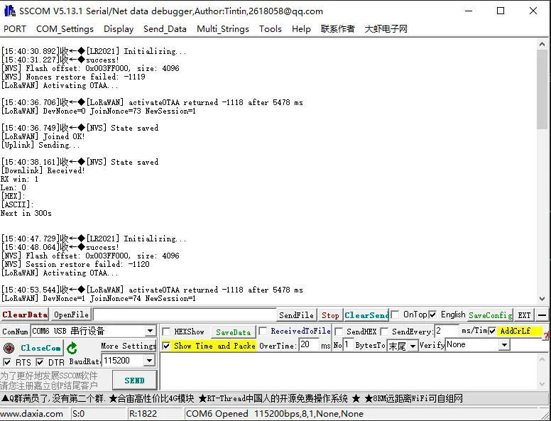
After flashing, the module automatically completes OTAA join, periodically reports data, and listens for downlink messages.
The serial port prints join status, uplink/downlink data, signal quality, etc., as shown below:
Working with Arduino
This chapter contains the following sections. Please read as needed:
Setting Up Development Environment
1. Installation and Configuration
- For setting up the Arduino environment and basic usage, please refer to this R4 link; R3 comes pre-installed by default.
- After setting up the environment, connect the sensor and download the example package.
2. Hardware Configuration
- The IO level of the Arduino development board must be 3.3V. If using 5V IO levels, a level shifter is required; otherwise the sensor may be damaged.
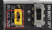
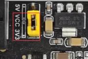
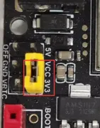
- When using Waveshare R3/R4, the following jumper caps must be set to 3.3V before use.
| Image | Description |
|---|---|
| Arduino UNO R3 |
| Arduino UNO R4 |
| Arduino UNO R4 WIFI |
Hardware Connection
Connect according to the table below.
| Core2021-XF | Arduino UNO |
|---|---|
| CLK | 13 |
| MISO | 12 |
| MOSI | 11 |
| CS | 10 |
| DIO11 | 2 |
| RESET | 3 |
| BUSY | 9 |
Example
- Arduino example programs are located in the
core2021-xf\examples\arduinodirectory of the example package. - Examples 01, 02, and 03 require two Core2021-XF modules: one for transmission and one for reception.
| Example | Basic Description | Dependency Library |
|---|---|---|
| 01_lr2021_tx | LR2021 Transmit | RadioLib |
| 02_lr2021_rx | LR2021 Receive | RadioLib |
| 03_lr2021_pingpong | LR2021 Ping‑Pong | RadioLib |
| 04_lr2021_tx_cw | LR2021 CW Mode Transmit | RadioLib |
| 05_lr2021_LoRaWAN | LoRaWAN (not available on Arduino R3) | RadioLib |
Select the development board:
Image Description 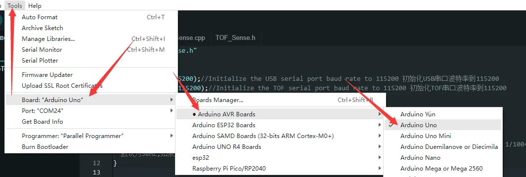
Arduino UNO R3 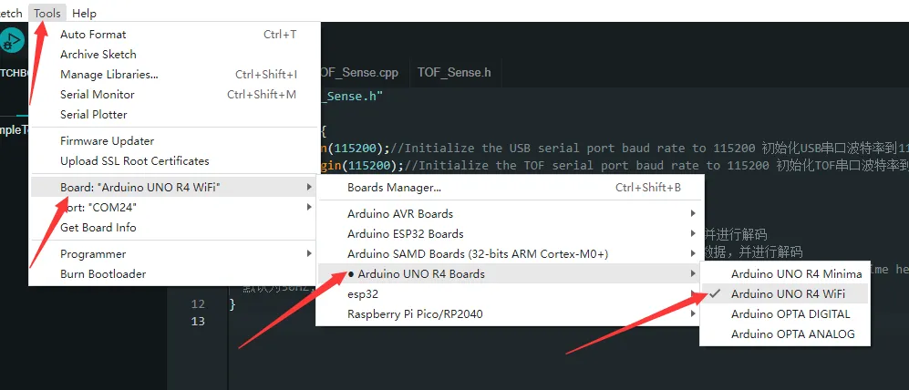
Arduino UNO R4 Select the port for the development board, then compile and upload.
After the upload is completed, open the serial port monitor, and the relevant information will be output.
01_lr2021_tx
Example Description
- Based on the Core2021-XF module, implements periodic LoRa packet transmission using interrupts.
- Uses non‑blocking transmission, does not occupy CPU resources in the main loop.
- After each packet is sent, automatically delays 1 second before sending the next packet.
- Supports string data transmission, with a built‑in packet sequence number for easy debugging.
Code Analysis
radio.irqDioNum = 11: Configures the LR2021 interrupt mapping pin; must be set before initialization.radio.XTAL = true: Enables the external crystal oscillator to ensure frequency accuracy.setFlag(void): Interrupt callback function triggered automatically after the module finishes transmission, sets a transmission‑complete flag.radio.setPacketSentAction(setFlag): Binds the transmission‑complete interrupt function.radio.startTransmit("content"): Starts asynchronous LoRa transmission (supports string / byte array).radio.finishTransmit(): Cleanup after transmission, turns off the transmit circuit and resets the module state.loop()main logic: Check transmission‑complete flag → print status → delay → send next packet with sequence number.
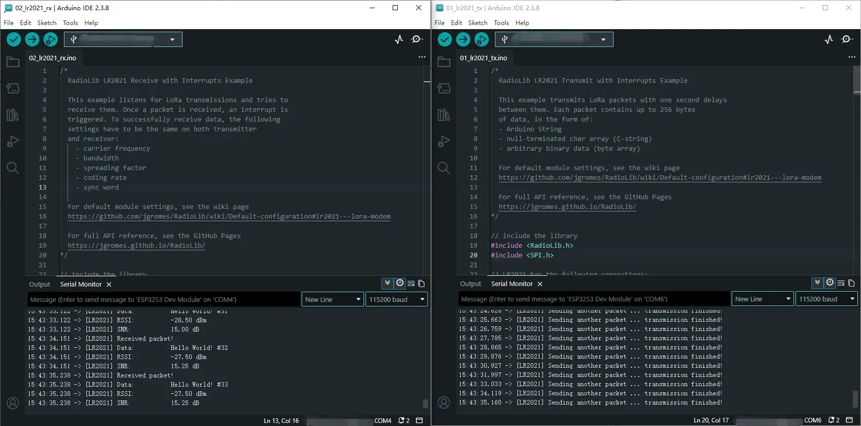
Operation Result
After compiling and uploading, open the serial monitor to see logs indicating transmission completion, as shown below (in combination with 02_lr2021_rx):
02_lr2021_rx
Example Description
- Based on the Core2021-XF module, implements wireless LoRa packet reception using interrupts.
- Uses non‑blocking listening mode; the module automatically waits for data without consuming CPU resources.
- After successful reception, automatically parses the data and prints the packet content, RSSI, and SNR.
- The same frequency, spreading factor, bandwidth, and coding rate must be configured on both the transmitter and receiver for successful communication.
Code Analysis
radio.irqDioNum = 11: Configures the LR2021 interrupt mapping pin; must be set before initialization.radio.XTAL = true: Enables the external crystal oscillator to ensure frequency accuracy and improve reception stability.setFlag(void): Interrupt callback function triggered automatically after a complete packet is received, sets a reception‑complete flag.radio.setPacketReceivedAction(setFlag): Binds the reception‑complete interrupt service function.radio.startReceive(): Starts continuous LoRa reception mode, enters a data‑waiting state.radio.readData(str): Reads the received wireless data (supports string parsing).radio.getRSSI() / radio.getSNR(): Retrieves signal quality parameters for debugging and link evaluation.loop()main logic: Check reception‑complete flag → read data → parse and print → continue listening.
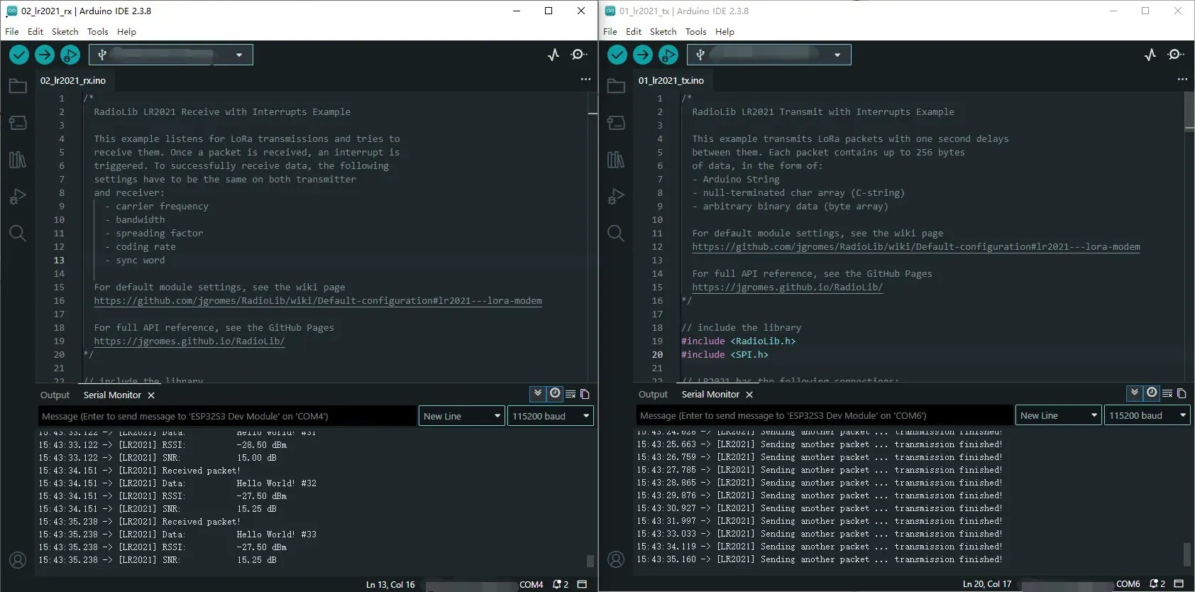
Operation Result
After compiling and uploading, open the serial monitor to see real‑time reception logs including data content, RSSI, and SNR, as shown below (in combination with 01_lr2021_tx):
03_lr2021_pingpong
Example Description
- Based on the Core2021-XF module, implements LoRa automatic ping‑pong (question‑answer) two‑way communication.
- Two modules can send and receive to each other without manual control.
- Enabling
INITIATING_NODEsets the module as the initiator; the other module acts as the responder. - Automatically switches between transmit and receive states, driven by non‑blocking interrupts.
Code Analysis
radio.irqDioNum = 11: Configures the LR2021 interrupt mapping pin; must be set before initialization.radio.XTAL = true: Enables the external crystal oscillator to ensure communication frequency accuracy.setFlag(void): General interrupt callback, triggered on either transmit or receive completion.radio.setIrqAction(setFlag): Binds the shared transmit/receive interrupt function.INITIATING_NODEmacro: Used to distinguish the initiating node.radio.startTransmit(): Starts packet transmission.radio.startReceive(): Switches the module to listening (receive) mode.radio.readData(str): Reads the received LoRa packet.loop()main logic: Transmit complete → enter receive; receive complete → delay reply → transmit again.
Operation Result
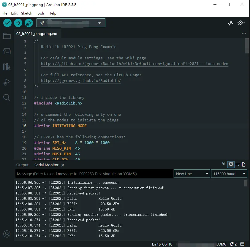
- Flash the program onto two modules, enabling the
INITIATING_NODEmacro on one of them. - After power‑on, they automatically send and receive to each other; the serial monitor prints the transmit/receive status, data, RSSI, and SNR, as shown below:
04_lr2021_tx_cw
Example Description
- Based on the Core2021-XF module, implements LoRa continuous wave (CW) / direct transmit.
- Outputs a fixed‑frequency carrier signal without packet formatting, used for band testing, signal detection, and instrument calibration.
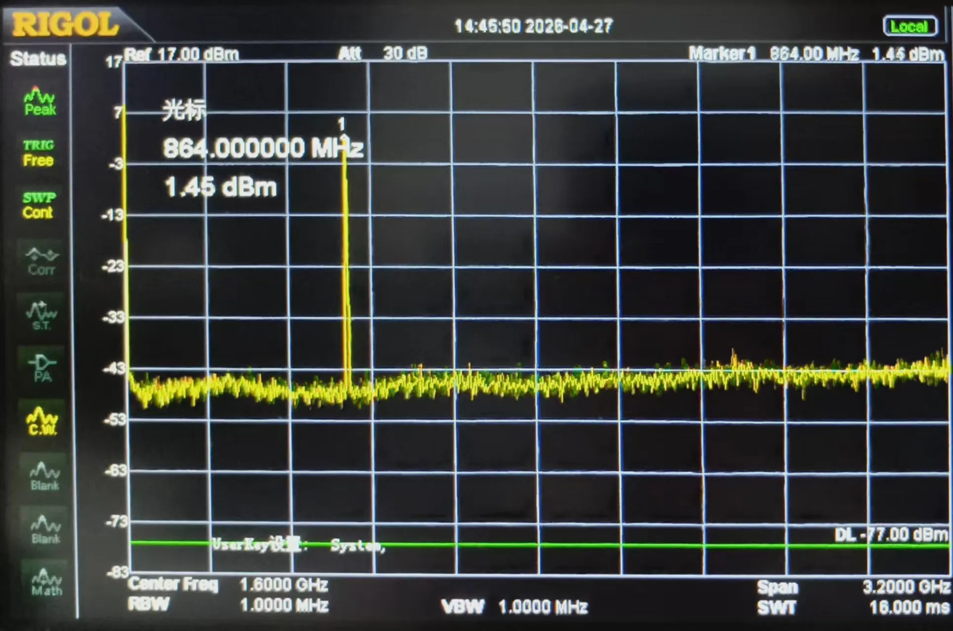
- Fixed frequency 868 MHz, transmit power 22 dBm.
- Upon power‑up, transmits continuously with no additional logic.
Code Analysis
radio.XTAL = true: Enables the external crystal oscillator to ensure carrier frequency accuracy.OUT_HZ 868000000UL: Defines the direct transmit frequency (868 MHz); can be modified.radio.setOutputPower(22): Sets the transmit power to 22 dBm.radio.transmitDirect(OUT_HZ): Enters continuous direct transmission mode, outputting a fixed‑frequency carrier.loop(): No business logic; the carrier continues to transmit without program intervention.
Operation Result
After flashing, the module immediately outputs a fixed‑frequency carrier signal.
The serial port prints initialization and transmission start status; a spectrum analyzer or receiving module can detect the continuous RF signal, as shown below:
05_lr2021_LoRaWAN
Example Description
- Based on the Core2021-XF module + Arduino UNO R4 platform, implements LoRaWAN OTAA join and uplink/downlink communication.
- Supports OTAA dynamic join, and EEPROM‑based session storage to quickly restore connection after power‑off reboot.
- Periodically sends uplink data (default every 5 minutes) and listens for server downlink messages.
- Automatically prints the received data in both HEX and ASCII formats, and supports signal quality monitoring.
Code Analysis
radio.irqDioNum = 11: Configures the LR2021 interrupt mapping pin; must be set before initialization.radio.XTAL = true: Enables the external crystal oscillator to ensure LoRaWAN frequency accuracy.EEPROM.begin(): Initializes the on‑chip EEPROM for storing LoRaWAN session information.restoreLoRaWANState(): Restores join session and random values from EEPROM to achieve fast reconnection.node.beginOTAA(): Initializes OTAA join parameters (JoinEUI, DevEUI, AppKey, NwkKey).node.activateOTAA(): Initiates an OTAA join request to the server.saveLoRaWANState(): Saves session information to EEPROM after successful join.node.sendReceive(): Sends uplink data and automatically opens receive windows to listen for downlink messages.printHex / printAscii: Prints the downlink data in hexadecimal and ASCII formats.
Operation Result
Refer to the LoRaWAN environment setup document for environment configuration.
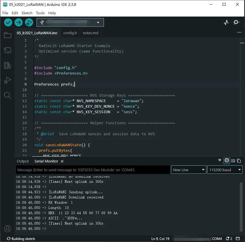
After flashing, the module automatically performs OTAA join; once joined successfully, it periodically uploads data.
The serial port prints join status, uplink/downlink messages, RSSI, SNR, etc., as shown below:
Working with Raspberry Pi
This chapter contains the following sections. Please read as needed:
Setting Up Development Environment
1. Installation and Configuration
- For Raspberry Pi system installation and usage, please refer to this link
- After successful booting, configure the Raspberry Pi environment
2. Download Example
sudo apt install cmake -y
sudo apt install -y liblgpio-dev
cd ~
# Download from github
git clone https://github.com/waveshare/core2021-xf.git
cd core2021-xf/examples/raspberrypi
3. Enable Raspberry Pi SPI Interface
- Enter the following command in the Raspberry Pi terminal:
sudo raspi-config nonint do_spi 0
Hardware Connection
Connect according to the table below.
| Core2021-XF | Raspberry Pi (BCM) |
|---|---|
| CLK | 11 |
| MISO | 9 |
| MOSI | 10 |
| CS | 25 |
| DIO11 | 17 |
| RESET | 22 |
| BUSY | 24 |
Example
- Raspberry Pi example programs are located in the
core2021-xf/examples/raspberrypidirectory of the example package. - Examples 01, 02, and 03 require two Core2021-XF modules: one for transmission and one for reception.
| Example | Basic Description | Dependency Library |
|---|---|---|
| 01_lr2021_tx | LR2021 Transmit | RadioLib |
| 02_lr2021_rx | LR2021 Receive | RadioLib |
| 03_lr2021_pingpong | LR2021 Ping‑Pong | RadioLib |
| 04_lr2021_tx_cw | LR2021 CW Mode Transmit | RadioLib |
| 05_lr2021_LoRaWAN | LoRaWAN | RadioLib |
01_lr2021_tx
Example Description
- Based on the Raspberry Pi + Core2021-XF module, implements periodic LoRa packet transmission using interrupts.
- Dedicated hardware pin configuration to match the Raspberry Pi SPI and GPIO interfaces.
- Uses non‑blocking transmission mechanism, efficient and stable.
- Automatically sends one packet of test data with sequence number every 1 second, suitable for long‑term stable operation.
Script Description
build.sh: Build script that automatically creates a build directory, generates a Makefile, compiles the project, and outputs the executable file.clean.sh: Clean script that quickly removes generated files and restores the project directory.
Code Analysis
PiHal* hal = new PiHal(0, SPI_FREQ_HZ): Raspberry Pi hardware initialization, configures SPI bus and clock.radio.irqDioNum = 11: Configures the LR2021 interrupt mapping pin.radio.XTAL = true: Enables the external crystal oscillator to ensure communication frequency accuracy.setFlag(void): Interrupt callback function that automatically sets a flag when transmission is complete.radio.setPacketSentAction(setFlag): Binds the transmit‑complete interrupt.radio.startTransmit(): Starts asynchronous LoRa packet transmission.radio.finishTransmit(): Turns off the RF circuit after transmission to ensure stable low‑power operation.- Main loop: Check transmission complete → print log → delay → send next packet.
** Program Usage**
- Go to the
lr2021_txdirectory and execute the following commands:
cd ~/core2021-xf/examples/raspberrypi/lr2021_tx
chmod +x *
./build.sh
./build/01_lr2021_tx
Operation Result
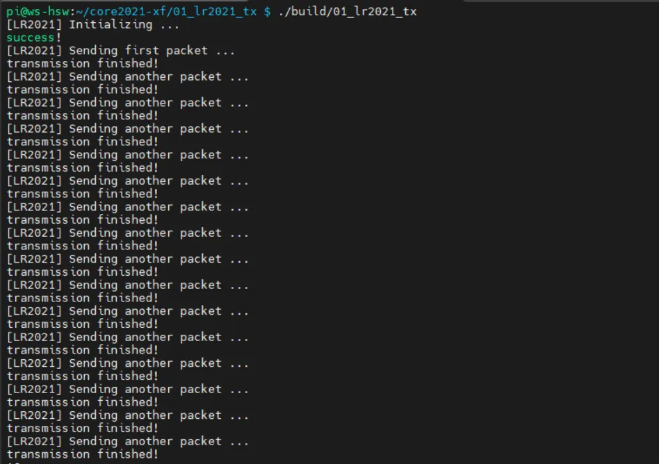
- After compilation and execution, the terminal prints the transmission status and packet sequence number in real time. Can be paired with a receiving module for communication testing.
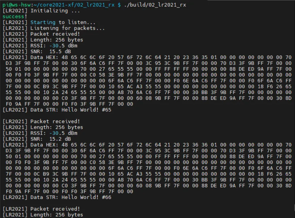
02_lr2021_rx
Example Description
- Based on the Raspberry Pi + Core2021-XF module, implements wireless LoRa packet reception using interrupts.
- Dedicated hardware pin configuration to match the Raspberry Pi SPI and GPIO interfaces.
- Uses non‑blocking listening mode, receives data in real time, efficient and stable.
- After successful reception, automatically prints the data length, RSSI, SNR, HEX format, and string format for easy debugging.
Script Description
build.sh: Build script that automatically creates a build directory, generates a Makefile, compiles the project, and outputs the executable file.clean.sh: Clean script that quickly removes generated files and restores the project directory.
Code Analysis
PiHal* hal = new PiHal(0, SPI_FREQ_HZ): Raspberry Pi hardware initialization, configures SPI bus and clock.radio.irqDioNum = 11: Configures the LR2021 interrupt mapping pin.radio.XTAL = true: Enables the external crystal oscillator to ensure communication frequency accuracy.setFlag(void): Interrupt callback function that automatically sets a flag when reception is complete.radio.setPacketReceivedAction(setFlag): Binds the receive‑complete interrupt.radio.startReceive(): Starts asynchronous LoRa listening mode.radio.readData(): Reads the received packet, supports HEX and string parsing.radio.getRSSI() / radio.getSNR(): Retrieves signal quality parameters.- Main loop: Check reception complete → parse data → print information → restart listening.
** Program Usage**
- Go to the
lr2021_rxdirectory and execute the following commands:
cd ~/core2021-xf/examples/raspberrypi/lr2021_rx
chmod +x *
./build.sh
./build/02_lr2021_rx
Operation Result
- After compilation and execution, the terminal prints the reception status, data content, and signal quality in real time. Can be paired with a transmitting module for complete communication testing.
03_lr2021_pingpong
Example Description
- Based on the Raspberry Pi + Core2021-XF module, implements LoRa automatic ping‑pong (question‑answer) two‑way communication.
- Dedicated hardware pin configuration to match the Raspberry Pi SPI and GPIO interfaces.
- Interrupt‑driven non‑blocking mode, automatically switches between transmit and receive states.
- Two devices can send and receive to each other without manual control, suitable for bidirectional link verification.
Script Description
build.sh: Build script that automatically creates a build directory, generates a Makefile, compiles the project, and outputs the executable file.clean.sh: Clean script that quickly removes generated files and restores the project directory.
Code Analysis
PiHal* hal = new PiHal(0, SPI_FREQ_HZ): Raspberry Pi hardware initialization, configures SPI bus and clock.radio.irqDioNum = 11: Configures the LR2021 interrupt mapping pin.radio.XTAL = true: Enables the external crystal oscillator to ensure communication frequency accuracy.setFlag(void): Common interrupt callback triggered on either transmit or receive completion.INITIATING_NODE: Macro to distinguish the initiating node.radio.startTransmit(): Starts packet transmission.radio.startReceive(): Switches the module to listening mode.radio.readData(): Reads the received LoRa packet and parses it.- Main logic: Send complete → enter receive; receive complete → delay reply → send again.
** Program Usage**
- Go to the
lr2021_pingpongdirectory and execute the following commands:
cd ~/core2021-xf/examples/raspberrypi/lr2021_pingpong
chmod +x *
./build.sh
./build/03_lr2021_pingpong
Operation Result
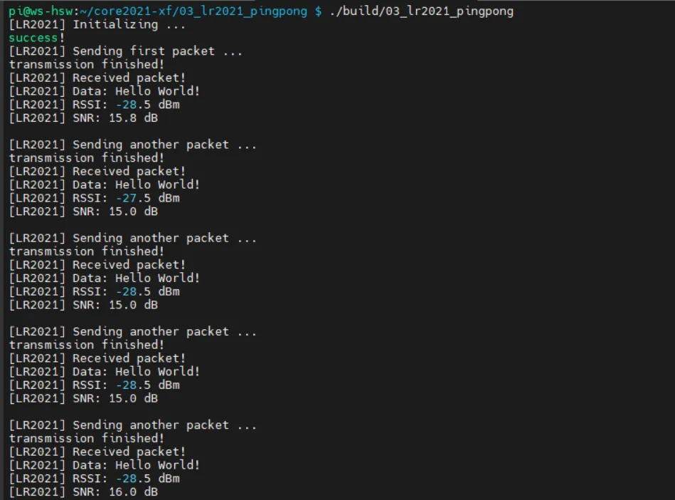
- Two Raspberry Pi devices automatically send and receive to each other; the terminal prints the send/receive status, data, RSSI, and SNR in real time.
04_lr2021_tx_cw
Example Description
- Based on the Raspberry Pi + Core2021-XF module, implements LoRa fixed‑frequency continuous wave (CW) transmission.
- Dedicated hardware pin configuration to match the Raspberry Pi SPI and GPIO interfaces.
- Outputs a clean continuous RF signal without packet formatting, used for instrument calibration, band testing, and signal detection.
- Transmission frequency: 868 MHz, transmit power: 22 dBm.
- Immediately starts continuous transmission after power‑on; the program runs stably with no additional operations.
Script Description
build.sh: Build script that automatically creates a build directory, generates a Makefile, compiles the project, and outputs the executable file.clean.sh: Clean script that quickly removes generated files and restores the project directory.
Code Analysis
PiHal* hal = new PiHal(0, SPI_FREQ_HZ): Raspberry Pi hardware initialization, configures SPI bus and clock.radio.XTAL = true: Enables the external crystal oscillator to ensure carrier frequency accuracy.OUT_HZ 868000000UL: Defines the continuous transmit frequency (868 MHz).radio.setOutputPower(22): Sets the transmit power to 22 dBm.radio.transmitDirect(OUT_HZ): Enters continuous direct transmission mode, outputting a fixed‑frequency carrier.
** Program Usage**
- Go to the
04_lr2021_tx_cwdirectory and execute the following commands:
cd ~/core2021-xf/examples/raspberrypi/04_lr2021_tx_cw
chmod +x *
./build.sh
./build/04_lr2021_tx_cw
Operation Result
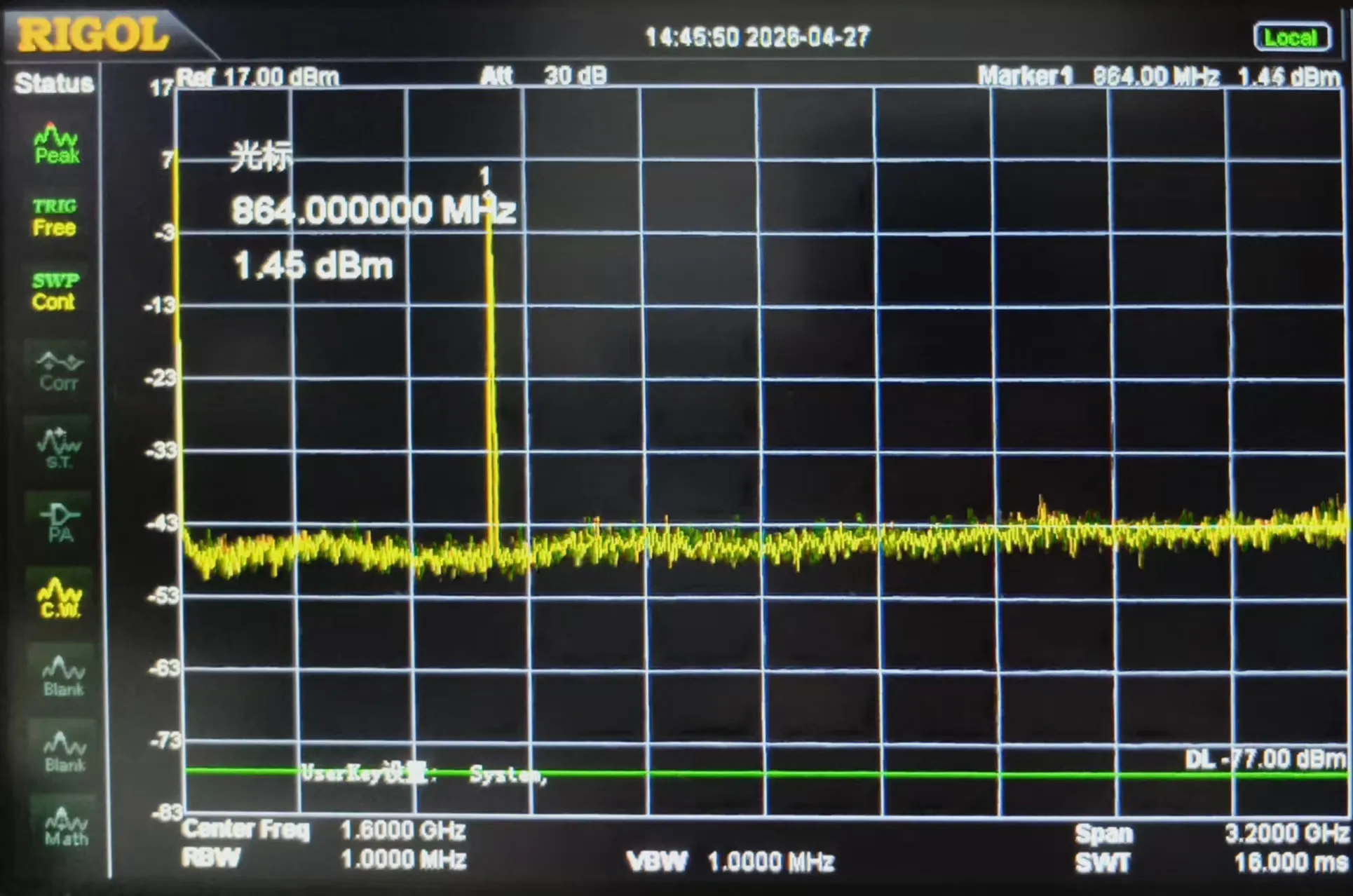
- After the program runs, the module immediately outputs a fixed‑frequency continuous carrier signal. A spectrum analyzer or receiving device can detect the stable RF signal.
05_lr2021_LoRaWAN
Example Description
- Based on the Raspberry Pi + Core2021-XF module, implements LoRaWAN OTAA join + periodic uplink + downlink reception.
- Uses the file
lorawan_state.binto persistently store session information, allowing fast reconnection after power‑off reboot without re‑joining. - Dedicated hardware pin configuration perfectly adapted to Raspberry Pi SPI/GPIO interfaces.
- Automatically uploads random test data every 5 minutes, supports downlink command parsing.
- Prints join status, signal quality, and uplink/downlink data in real time for easy debugging and deployment.
Script Description
build.sh: Build script that automatically creates a build directory, generates a Makefile, compiles the project, and outputs the executable file.clean.sh: Clean script that quickly removes generated files and restores the project directory.
Code Analysis
PiHal* hal = new PiHal(0, SPI_FREQ_HZ): Raspberry Pi hardware initialization, SPI0 + 8 MHz clock.radio.irqDioNum = 11: Configures the LR2021 interrupt mapping to ensure stable communication.radio.XTAL = true: Enables the external crystal oscillator to ensure LoRaWAN frequency accuracy.saveLoRaWANState(): Saves session data to a local file for persistence.restoreLoRaWANState(): Recovers session from the file, supports fast reconnection.node.beginOTAA()/node.activateOTAA(): OTAA join key functions.node.sendReceive(): Sends uplink data and listens for server downlink messages.printHex / printAscii: Formats and prints downlink data.
** Program Usage**
- Go to the
05_lr2021_LoRaWANdirectory and execute the following commands:
cd ~/core2021-xf/examples/raspberrypi/05_lr2021_LoRaWAN
chmod +x *
./build.sh
./build/05_lr2021_LoRaWAN
Operation Result
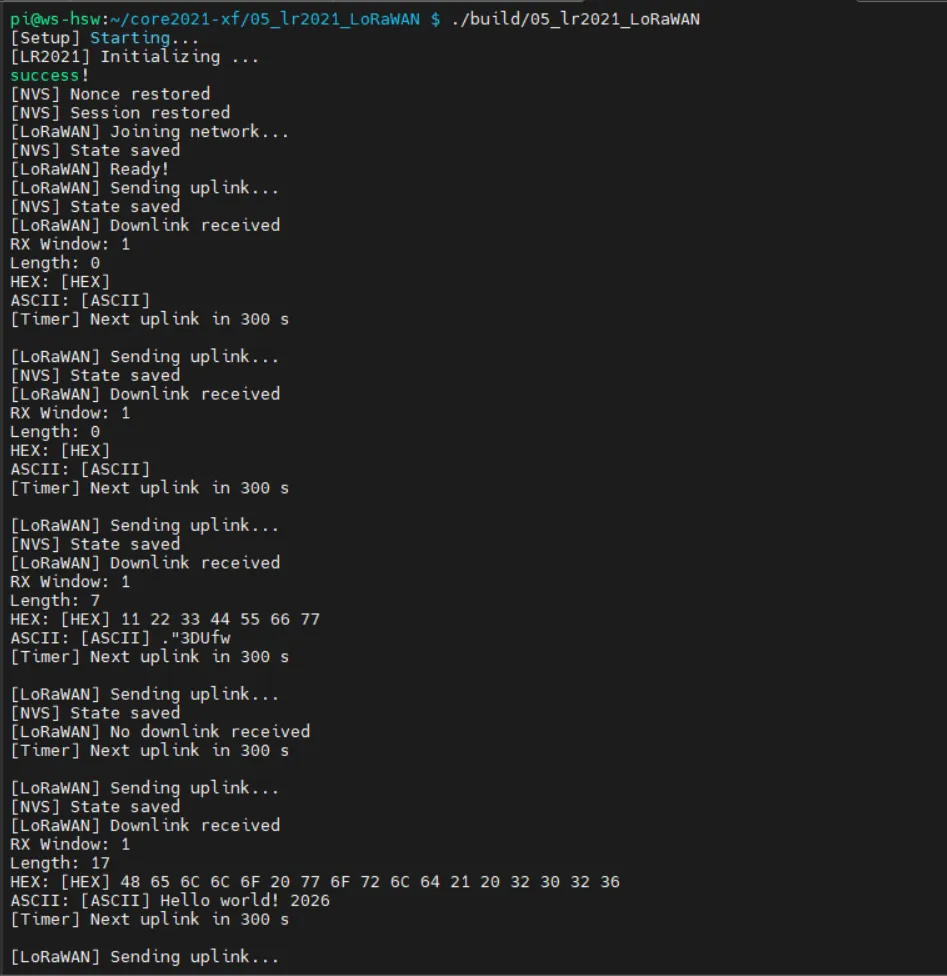
- After the program runs, it automatically completes OTAA join, periodically reports data, and listens for server downlink messages.
- The terminal prints join status, upload records, signal quality, and downlink content in real time, running stably and reliably.
Working with STM32
- This chapter demonstrates examples from the official LoRa USP library
- For related documentation, please visit the official GitHub: USP Documentation
Hardware Connection
Connect according to the table below:
| Core2021-XF | STM32L476RG |
|---|---|
| CLK | PA5 |
| MISO | PA6 |
| MOSI | PA7 |
| CS | PA8 |
| DIO8 | PA1 |
| RESET | PA0 |
| BUSY | PB3 |
Example
- STM32 example programs are located in the
examples/main_examplesdirectory of Lora-net/usp. - Testing requires two Core2021-XF modules: one for transmission and one for reception.
- The following describes several example programs, including usage and operational effects.
main_porting_tests
Example Description
- Based on STM32L476RG + Core2021-XF, implements porting functionality verification examples
- Used to test the following:
- SPI interface functionality
- Interrupt IRQ response
- Timers and low‑power modes
- Random number generation
- Radio configuration time
- MCU sleep time
- Flash emulation storage (optional)
- Tests cover module initialization, TX/RX configuration, and MCU‑related hardware interfaces
- Test results are printed via the serial port
Code Analysis
- Hardware abstraction layers:
smtc_modem_hal.h,smtc_hal_mcu.h,smtc_hal_gpio.h,smtc_hal_watchdog.h- IRQ callback functions:
radio_tx_irq_callback,radio_rx_irq_callback,timer_irq_callback
- LoRa/Radio parameters:
ralf_params_lora_t rx_lora_param/tx_lora_param: simulated RX/TX configurations for porting tests- Fixed frequency, symbol rate, bandwidth, sync word, and transmit power
- Main test functions:
porting_test_spi(): Verifies SPI port and chip firmware versionporting_test_radio_irq(): Verifies TX/RX interrupt triggeringporting_test_get_time(): Checks HAL time‑getting functionporting_test_timer_irq(): Verifies timer interruptsporting_test_stop_timer(): Verifies timer stop functionalityporting_test_disable_enable_irq(): Verifies interrupt disable/enable logicporting_test_random(): Verifies random number generation and distributionporting_test_config_rx_radio()/porting_test_config_tx_radio(): Checks RX/TX configuration timeporting_test_sleep_ms(): Checks MCU sleep timeporting_test_timer_irq_low_power(): Verifies timer interrupts in low‑power mode
- Flash tests (optional):
porting_test_flash()/test_context_store_restore() main_porting_tests():- Initializes MCU peripherals
- Disables IRQs to avoid initialization conflicts
- Runs porting tests in a loop and optionally performs Flash tests based on
ENABLE_TEST_FLASH - After completion, enters an infinite loop and refreshes the watchdog
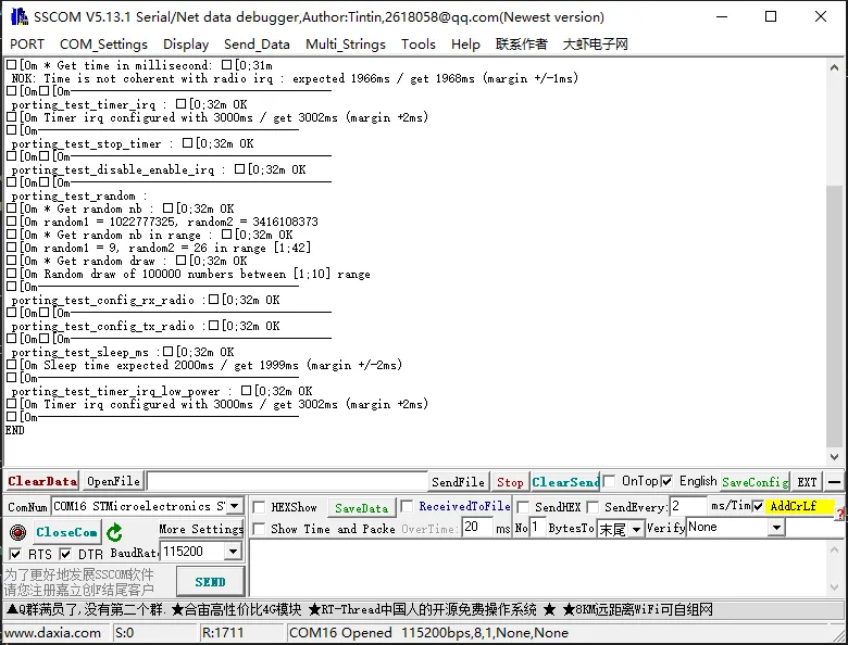
Operation Result
- After power‑on, the serial port prints:
ping_pong_example
Example Description
- Based on STM32L476RG + Core2021-XF, implements a Ping‑Pong + Periodic Uplink communication example
- Supports Manager mode triggered by a user button:
- The Manager initiates a PING
- The Subordinate automatically responds with a PONG
- Callbacks are triggered automatically after each transmission or reception
- Supports periodic uplink (sends a fixed payload
"LoRa"every 10 seconds by default) - LED indicators for TX/RX status
- Uses a watchdog to prevent MCU lock‑up
- Automatically enters low‑power sleep to save energy
Code Analysis
- MCU initialization:
hal_mcu_init(): Initializes MCU peripheralssmtc_rac_init(): Initializes the Radio Abstraction Layer
- User button:
user_button_tstores button state and press durationuser_button_callback(): Debounces the button and triggers Manager mode
- LED initialization:
SMTC_LED_TX/SMTC_LED_RX - Application initialization:
ping_pong_init(): Initializes Ping‑Pong transactionsperiodic_uplink_init(): Initializes periodic uplink
- Main loop:
- Reload watchdog:
hal_watchdog_reload() - Run radio transactions:
smtc_rac_run_engine() - Process button events:
ping_pong_on_button_press() - MCU sleep: determine if there are pending transactions, then call
hal_mcu_set_sleep_for_ms(SLEEP_DELAY)
- Reload watchdog:
- Core logic:
ping_pong_init(): Sets transaction context, payload, and modulation parametersping_pong_tx()/ping_pong_rx(): Sends/receives PING or PONGpre_ping_pong_callback()/post_ping_pong_callback():- LED control
- Handles transaction completion status (TX_DONE, RX_PACKET, RX_TIMEOUT, CRC_ERROR, TASK_ABORTED)
- Automatically retries or restarts
- Periodic uplink logic: schedules the next transmission via a callback function
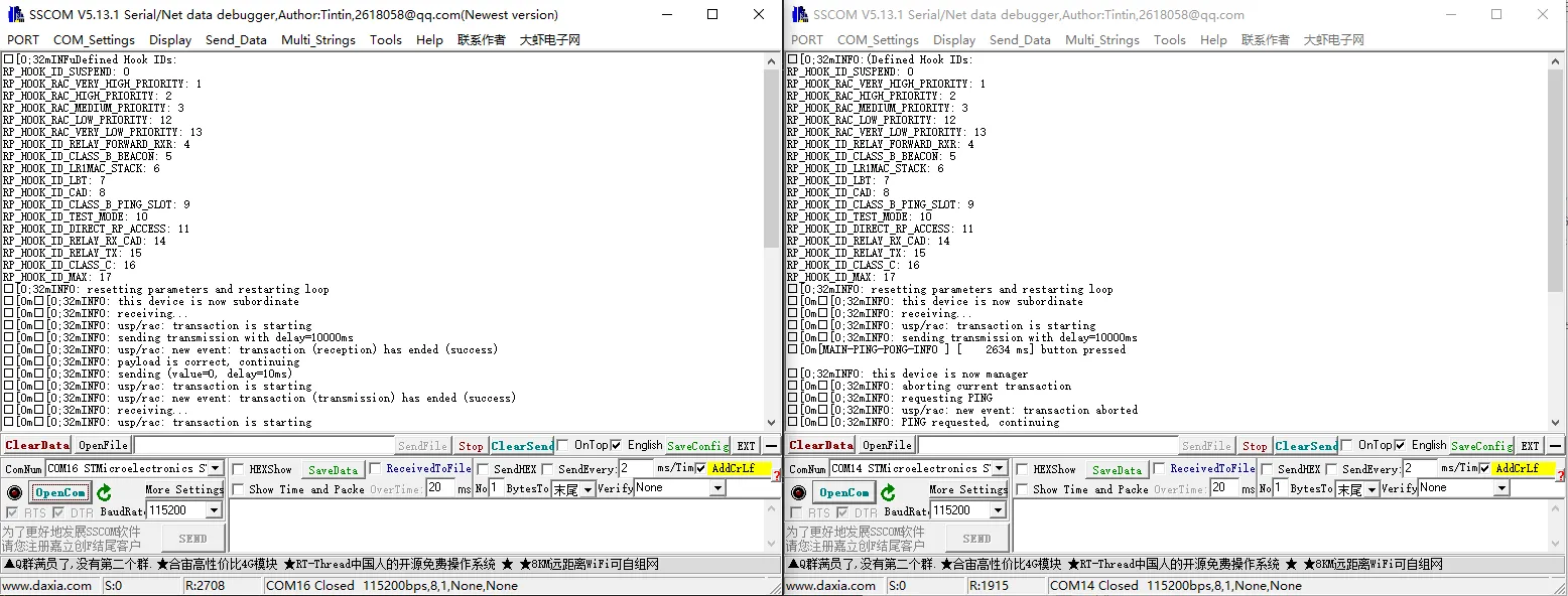
Operation Result
- After power‑on, the serial port prints:
main_periodical_uplink
Example Description
- Based on STM32L476RG + Core2021-XF, implements:
- LoRaWAN OTAA join
- Periodic uplink
- Immediate uplink triggered by a user button
- Uses
example_options.hto provide LoRaWAN credentials:USER_LORAWAN_DEVICE_EUIUSER_LORAWAN_JOIN_EUIUSER_LORAWAN_GEN_APP_KEYUSER_LORAWAN_APP_KEY
- Region configuration:
MODEM_EXAMPLE_REGION(EU868 or WW_2G4) - Watchdog and low‑power sleep protect the MCU
- Serial port prints events, uplink/downlink data, and debug information
Code Analysis
- Initialization:
hal_mcu_init(),hal_gpio_init_in()configure peripheralssmtc_rac_init()andsmtc_modem_init()initialize the modem, with callbackmodem_event_callback()
- User button:
user_button_callback()handles button events and triggers an immediate uplink
- Periodic uplink:
periodical_uplink_init()initializes the transaction- After each transmission,
post_periodic_callback()schedules the next uplink
- Event callback:
modem_event_callback()handles various modem events:RESET: sets credentials and region, initiates JoinJOINED: successful join, starts the first periodic uplinkALARM: periodic uplink triggerTXDONE: uplink transmission completedDOWNDATA: downlink data received- Other events (
LINK_CHECK,CLASS_B_PING_SLOT_INFO, etc.) print debug information
- Uplink data:
- 32-bit uplink counter
- Optional port for transmission (default 101/102)
- Main loop:
- Checks the button for immediate uplink
- Calls
smtc_modem_run_engine()andsmtc_rac_run_engine()to process transactions - MCU sleeps until the next transaction or watchdog reload
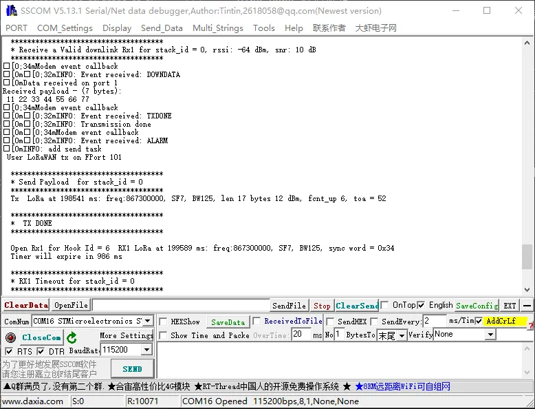
Operation Result
- After power‑on, the serial port prints:
LoRaWAN Environment Setup
LoRa and LoRaWAN
What is LoRa?
Semtech's LoRa is a long-range, low-power wireless platform for the Internet of Things (IoT). Generally, it refers to radio frequency chips using LoRa technology. Its main features are as follows:
LoRa (short for long range) uses a spread spectrum modulation technology derived from Chirp Spread Spectrum (CSS) technology. It is a type of long-distance wireless transmission technology and LPWAN communication technology. Spread spectrum technology trades bandwidth for sensitivity. Technologies like Wi-Fi and ZigBee also use spread spectrum, but LoRa modulation is characterized by approaching the Shannon-Hartley theorem limit, maximizing sensitivity improvement. Compared to traditional FSK technology, at the same communication rate, LoRa has 8~12 dBm better sensitivity than FSK. Currently, LoRa primarily operates in the Sub-GHz ISM bands.
LoRa technology integrates digital spread spectrum, digital signal processing, and forward error correction coding, significantly improving long-distance communication performance. LoRa's link budget is superior to any other standardized communication technology; the link budget is the main factor determining distance in a given environment.
LoRa RF chips mainly include the SX127X series, SX126X series, and SX130X series. The SX127X and SX126X series are used for LoRa nodes, while the SX130X series is used for LoRa gateways. For details, refer to Semtech's product list.
What is LoRaWAN?
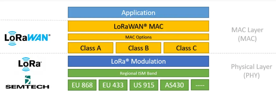
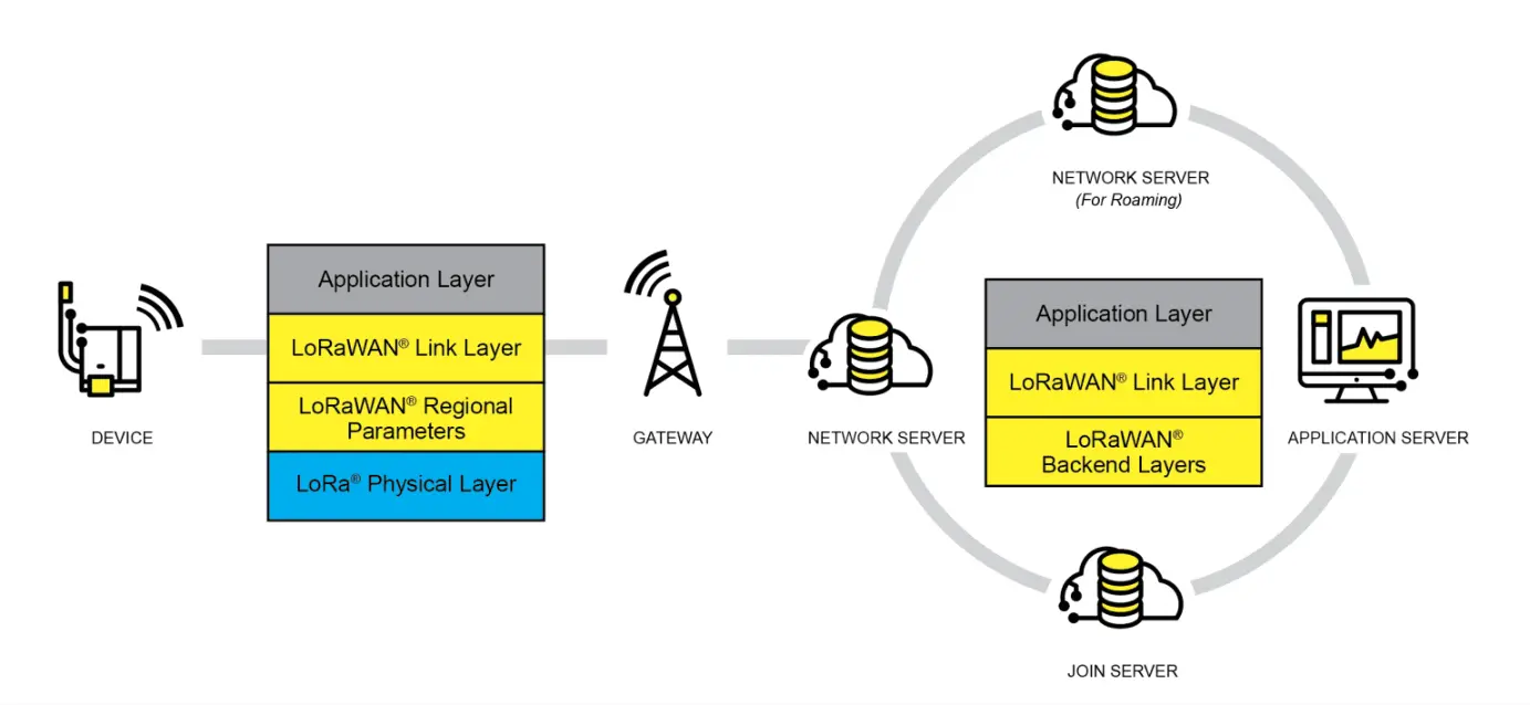
LoRaWAN is an open protocol for Low-Power Wide-Area Networks (LPWAN) built on top of the LoRa radio modulation technique. It is designed to wirelessly connect battery-powered "things" to the internet in regional, national, or global networks, targeting key IoT requirements such as bidirectional end-to-end communication, end-to-end security, mobility, and localization services. Nodes require network join authentication to connect wirelessly to the internet, establishing an encrypted communication channel between the node and the server. The LoRaWAN protocol layers are shown in the figure below.
The Class A/B/C node device types in the MAC layer cover almost all IoT application scenarios. The difference between them lies in the transmission and reception time slots of the nodes.
In the Modulation layer, parameters like EU868 and AS430 indicate different frequency bands used in different countries. Please refer to the link for regional parameters.
Implementing a LoRaWAN network covering a city or other area requires four components: nodes (LoRa node RF chips), gateways (or base stations, LoRa gateway RF chips), servers, and the cloud, as shown in the figure below.
A DEVICE (node device) must first initiate a join request packet to the GATEWAY and then to the server. Only after successful authentication can it normally send and receive application data with the server.
The GATEWAY can communicate with the server via wired networks or 3/4/5G wireless networks.
Major server-side operators include TTN, etc. For setting up your own cloud service, please refer to lorawan-stack or chirpstack.
Application
- This application is based on the official LoRaWAN example
ModemE_application_examplesand only demonstrates the basic LoRaWAN Class A application. Other advanced examples can be ported from the official repository, including: Join Request, LoRaWAN Class B application, LoRaWAN Multicast Class B/C examples, and FUOTA examples.
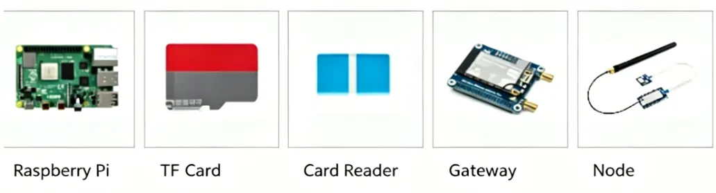
Required Components
Raspberry Pi 4B (with compatible power supply)
TF card (TF card with a capacity greater than 8GB is recommended)
Card reader
Gateway device
Node device
Development board (optional models): ESP32, Raspberry Pi, STM32, and Raspberry Pi Pico
Server Setup
This example uses ChirpStack as the LoRaWAN network server. Please follow the official Raspberry Pi installation steps for configuration.
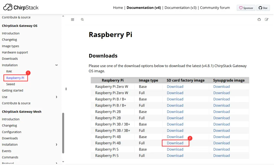
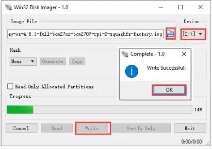
First, download the ChirpStack Gateway OS image, extract it, and use Win32DiskImager to write the image to the TF card.
Downloading the Image
Writing the Image
After writing, please refer to the official documentation for detailed configuration. This document only provides a brief installation guide. For details, see: ChirpStack Gateway OS Getting Started Guide.
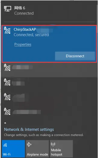
Insert the TF card into the Raspberry Pi and power it on. After booting, your computer's Wi-Fi should detect a wireless hotspot named
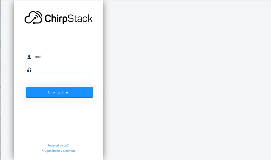
ChirpStackAP-XXXXXXwith the passwordChirpStackAP. After connecting successfully, access192.168.0.1in a browser to open the ChirpStack management interface. No password is required for the first login.Connecting to Wi-Fi
Accessing the Web Interface
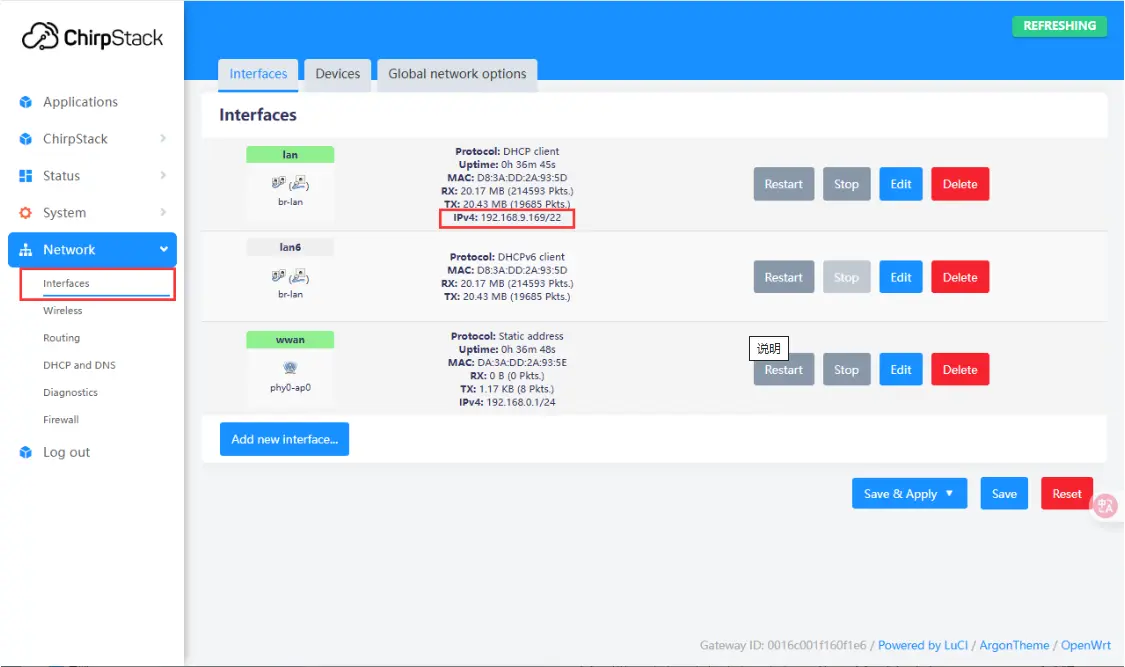
After booting, you can connect to an external network via Ethernet or Wi-Fi. Here, connecting via Ethernet is used as an example. To configure Wi-Fi, please refer to: Wi-Fi Configuration. After connecting to the network, you can view the current IP address in the web management interface.
Adding a Gateway
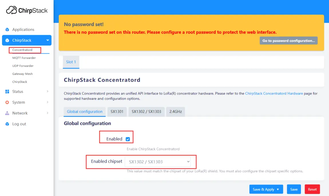
After the server configuration is complete and the IP address is obtained, power off the Raspberry Pi and disconnect the power. Connect the SX1303-868M-LoRaWAN-Gateway-HAT (gateway device) to the Raspberry Pi and attach the antenna. Power on the Raspberry Pi. In your browser, navigate to the previously obtained IP address to enter the ChirpStack management interface. Click ChirpStack -> Concentratord and enable the gateway function. Using the SX1303 (868 MHz) as an example, configure it as shown below, then click "Save & Apply":
Enabling the Gateway
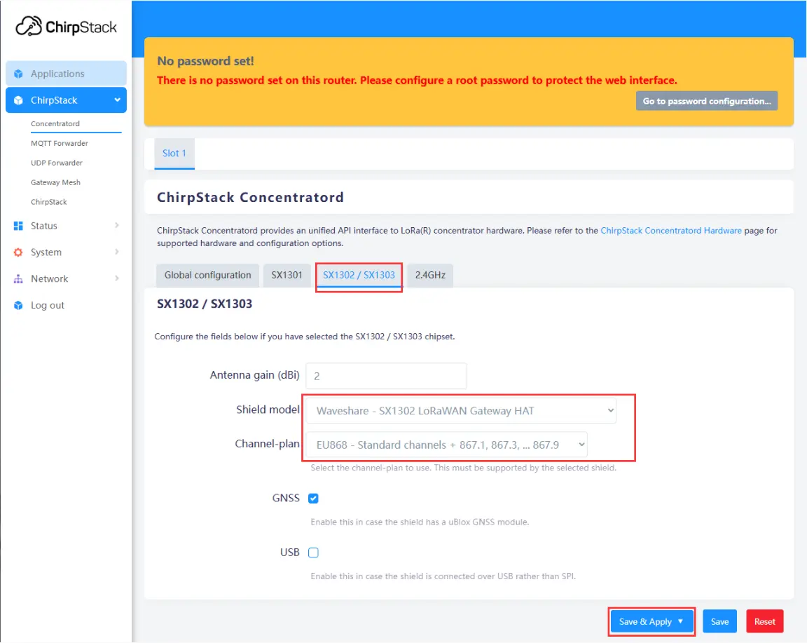
Configuring Gateway Parameters
Use the IP address obtained earlier to access the device remotely via an SSH tool (e.g., MobaXterm). The default username is
root. After a successful connection, enter the following command in the terminal to get the gateway ID:gateway-id. The system will output the current device's gateway ID. Make a note of this ID; it will be needed when adding the gateway later.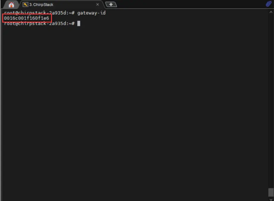
Navigate to Applications -> ChirpStack. The first time you enter, you need to log in. The default username and password are both
admin. After logging in, click Gateways -> Add gateway, fill in the gateway-id obtained earlier on the Add page, and save it. Return to the Gateway page to see if the gateway has been successfully launched.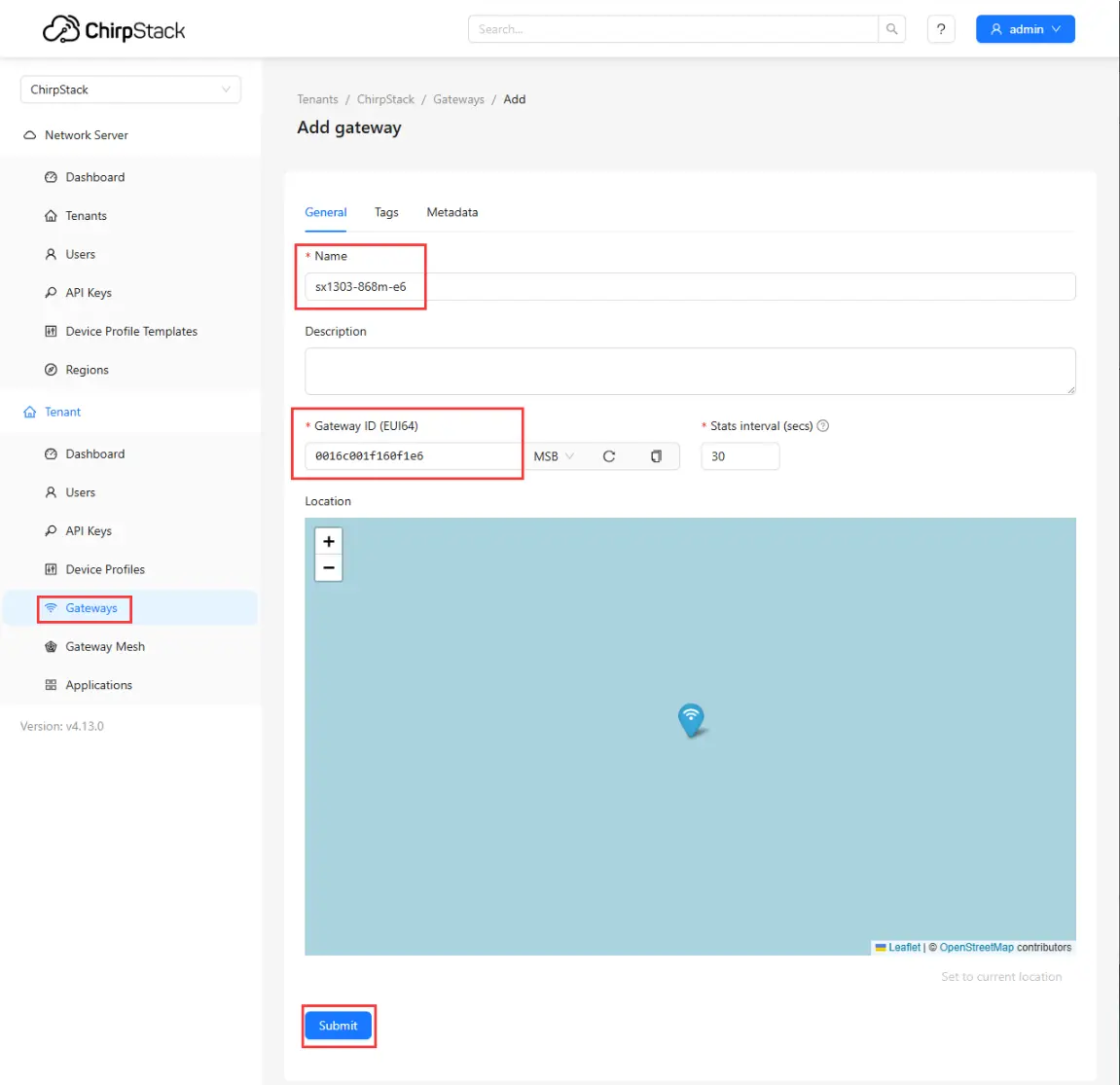
Adding Gateway to Server
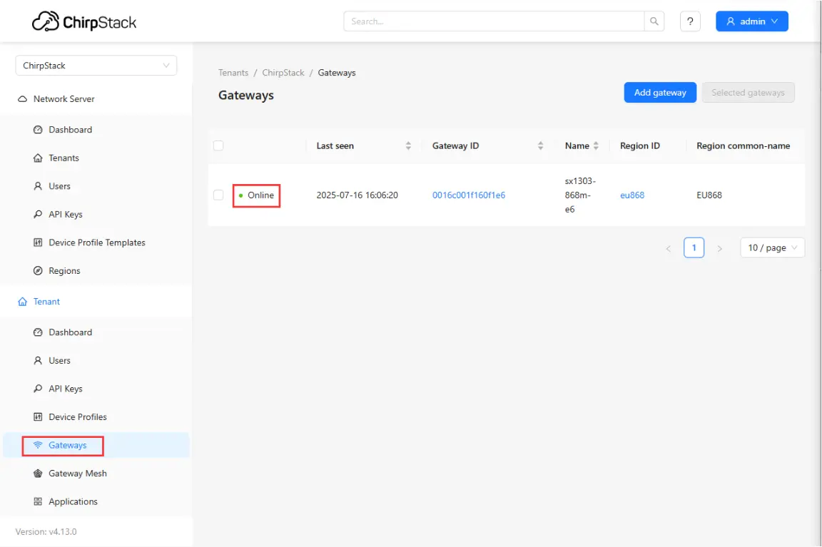
Checking if Gateway is Online
Adding a Node
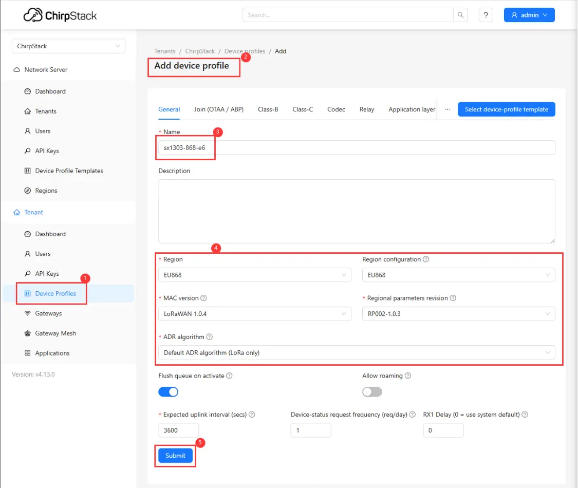
This example uses the Core1121‑XF as the node.
First, add a device profile in the web interface: Device Profiles -> Add device profile. Configure as shown in the figure below:
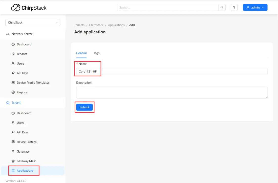
Then, add an application: Applications -> Add application, fill in the relevant information, and save:

Setting EUI
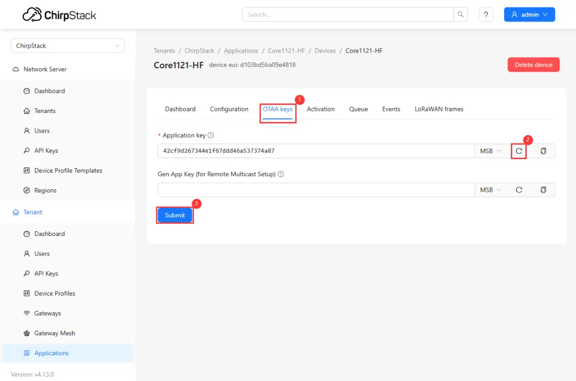
Setting Key
Use the
05_lr2021_LoRaWANexample program. Open it and go to the directory:core2021-xf\examples\arduino\05_lr2021_LoRaWAN. Edit theconfig.hfile and fill in the EUI and keys generated earlier in the corresponding fields. Then compile and flash.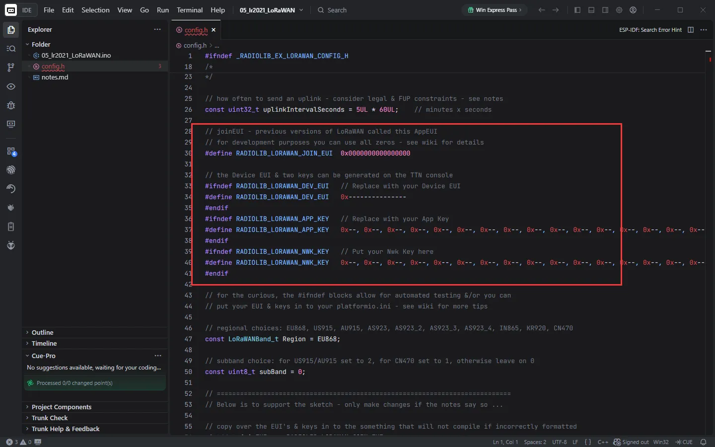
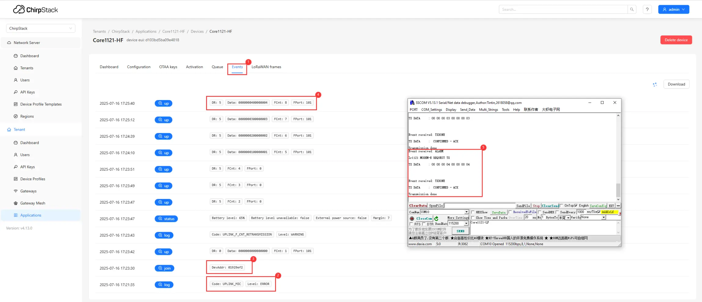
After flashing, the node will automatically request to join the LoRaWAN network. Upon successful joining, the node will periodically send uplink data. You can view device events and communication status through the web interface:
①. Click Events to view the node's operating status.
②. Check for join failures.
③. If joining is successful, you can see the join event.
④. View the data reported by the node.
⑤. View debug information via the serial port.
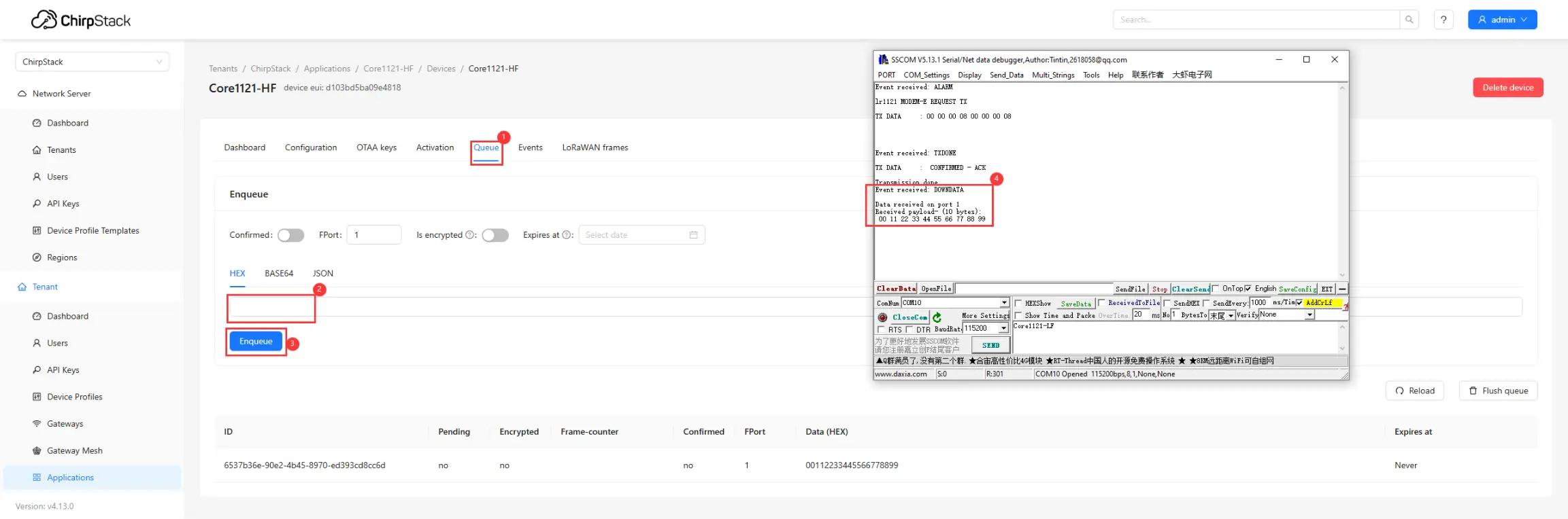
The server also supports sending downlink data to the node:
①. Click Queue.
②. Enter the hexadecimal data to be sent.
③. Click Send.
④. The node receives the data and prints it on the serial port.
Resources
1. Hardware Resources
Development Board Design Files
2. Documentation and Manuals
3. Example
Support
Monday-Friday (9:30-6:30) Saturday (9:30-5:30)
Email: services01@spotpear.com
[Tutorial Navigation]
- Features
- Specifications
- Interface Description
- Dimensions
- Working with ESP32S3
- Setting Up Development Environment
- Hardware Connection
- Example
- Run Arduino ESP32 Example
- Run ESP-IDF Example
- Working with Raspberry Pi Pico
- Setting Up Development Environment
- Hardware Connection
- Example
- Arduino Pico Examples
- C/C++ Examples
- Working with Arduino
- Working with Raspberry Pi
- Working with STM32
- LoRaWAN Environment Setup
- Application
- Resources
- Support