


- sales/support
Google Chat:---
- sales
+86-0755-88291180
- sales01
sales@spotpear.com
- sales02
dragon_manager@163.com
- support
tech-support@spotpear.com
- CEO-Complaints
zhoujie@spotpear.com
- Only Tech-Support
WhatsApp:13246739196
- Purchase/Shipping/Refund
WhatsApp:13424403025
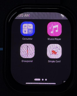
- HOME
- >
- ARTICLES
- >
- Common Moudle
- >
- ESP
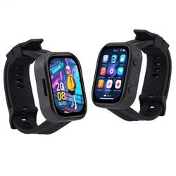
ESP32-S3-Touch-AMOLED-2.06 User Guide
Introduction
Introduction
ESP32-S3-Touch-AMOLED-2.06 is a high-performance, wearable watch-shaped development board launched by Waveshare. The product is based on the ESP32-S3R8 microcontroller, integrating a 2.06inch capacitive touch HD AMOLED screen, a six-axis sensor, RTC, an audio codec chip and power management and other functional modules. With a custom case, it looks and forms like a smart watch and is designed for prototyping and functional verification of wearable applications.
Features
- Equipped with ESP32-S3R8 high-performance Xtensa 32-bit LX7 dual-core processor, up to 240MHz main frequency
- Supports 2.4GHz Wi-Fi (802.11 b/g/n) and Bluetooth 5 (BLE), with onboard antenna
- Built in 512KB SRAM and 384KB ROM, with onboard 8MB PSRAM and an external 32MB Flash
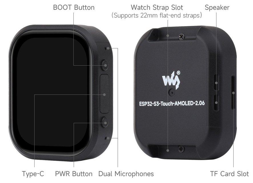
- Adopts Type-C interface to improve user convenience and device compatibility
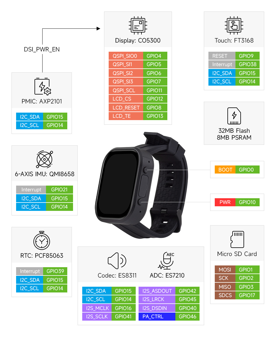
Hardware Description
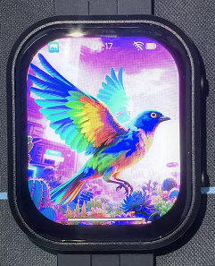
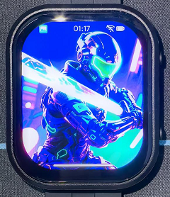
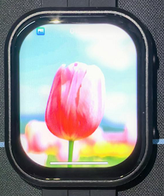
- Onboard 2.06inch high-definition capacitive touch AMOLED screen with a resolution of 410×502, 16.7M colors for clear color pictures
- Embedded with CO5300 driver chip and FT3168 capacitive touch chip, communicating through QSPI and I2C interfaces respectively, minimizes required IO pins
- Onboard QMI8658 6-axis IMU (3-axis accelerometer and 3-axis gyroscope) for detecting motion gesture, step counting, etc.
- Onboard PCF85063 RTC chip connected to the battery via the AXP2101 for uninterrupted power supply
- Onboard PWR and BOOT two side buttons with customizable functions, allowing for custom function development
- Onboard 3.7V MX1.25 lithium battery recharge/discharge header
- Bring out 1 x I2C port, 1 x UART port, and 1 x USB pad, which can be used for external device connection and debugging
- Onboard TF card slot for extended storage and fast data transfer, flexible for data recording and media playback, simplifying circuit design
- The benefits of using AXP2101 include efficient power management, support for multiple output voltages, charging and battery management functions, and optimization for battery life
- The AMOLED screen has the advantages of higher contrast, wider viewing angle, richer colors, faster response, thinner design, lower power consumption, and flexibility
Pinout Definition
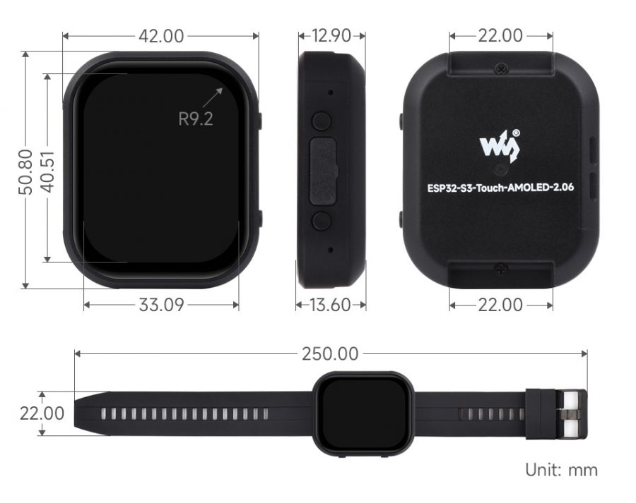
Dimensions
Screen Description
Touch and its Controller
- This touch screen is composed of surface toughened glass + thin film material, which has high strength, high hardness, and good light transmittance. It is equipped with FT3168 self-capacitance touch chip as the driver chip, which supports the I2C communication protocol standard and can realize a 10Khz~400Khz configurable communication rate.
Usage Instructions
ESP32-S3-Touch-AMOLED-2.06 currently provides two development tools and frameworks, Arduino IDE and ESP-IDF, providing flexible development options, you can choose the right development tool according to your project needs and personal habits.
Development Tool
| Arduino IDEArduino IDE is an open source electronic prototyping platform, convenient and flexible, easy to get started. After a simple learning, you can start to develop quickly. At the same time, Arduino has a large global user community, providing an abundance of open source code, project examples and tutorials, as well as rich library resources, encapsulating complex functions, allowing developers to quickly implement various functions. |
| ESP-IDFESP-IDF, or full name Espressif IDE, is a professional development framework introduced by Espressif Technology for the ESP series chips. It is developed using the C language, including a compiler, debugger, and flashing tool, etc., and can be developed via the command lines or through an integrated development environment (such as Visual Studio Code with the Espressif IDF plugin). The plugin offers features such as code navigation, project management, and debugging, etc. |
Each of these two development approaches has its own advantages, and developers can choose according to their needs and skill levels. Arduino are suitable for beginners and non-professionals because they are easy to learn and quick to get started. ESP-IDF is a better choice for developers with a professional background or high performance requirements, as it provides more advanced development tools and greater control capabilities for the development of complex projects.
Components Preparation
- ESP32-S3-Touch-AMOLED-2.06 x1
- TF card x 1
- USB cable (Type-A male to Type-C male) x1
Precautions for the use of lithium batteries
- Lithium polymer and lithium-ion batteries are very unstable. They may cause fire, personal injury, or property damage, if they're not properly recharged or used.
- When charging and discharging the battery pack, never connect the electrodes incorrectly. Do not use inferior charger/charging panel to recharge the battery.
- Do not mix and use old batteries with new ones, and avoid using batteries from other brands.
- If you need to purchase additional lithium-ion battery products, ensure that the battery parameters are compatible with the lithium-ion battery expansion board. It is recommended to choose batteries from legitimate manufacturers and perform your own aging tests to ensure that the lithium-ion battery can operate stably and safely.
- Lithium batteries have a cycle life, please replace the old batteries with new ones when it reaches the end of its useful life or uses it for two years, whichever comes first.
- Please handle battery products properly, keep them away from flammable and explosive items, and keep them out of reach of children to avoid accidents due to improper storage.
Working with Arduino
This chapter introduces setting up the Arduino environment, including the Arduino IDE, management of ESP32 boards, installation of related libraries, program compilation and downloading, as well as testing demos. It aims to help users master the development board and facilitate secondary development.

Environment Setup
Download and Install Arduino IDE
- Click to visit the Arduino official website, select the corresponding system and system bit to download
- Run the installer and install all by default
Install ESP32 Development Board
- Before using ESP32-related motherboards with the Arduino IDE, you must first install the software package for the esp32 by Espressif Systems development board
- According to board installation requirement, it is generally recommended to use Install Online. If online installation fails, use Install Offline.
- For the installation tutorial, please refer to Arduino board manager tutorial
| Board name | Board installation requirement | Version number requirement |
|---|---|---|
| esp32 by Espressif Systems | "Install Offline" / "Install Online" | ≥3.2.0 |
Install Library
- When installing Arduino libraries, there are usually two ways to choose from: Install online and Install offline. If the library installation requires offline installation, you must use the provided library file
For most libraries, users can easily search and install them through the online library manager of the Arduino software. However, some open-source libraries or custom libraries are not synchronized to the Arduino Library Manager, so they cannot be acquired through online searches. In this case, users can only manually install these libraries offline. - ESP32-S3-Touch-AMOLED-2.06 library file is stored in the sample program, click here to jump: ESP32-S3-Touch-AMOLED-2.06 Demo
- For library installation tutorial, please refer to Arduino library manager tutorial
| Library Name | Description | Version | Library Installation Requirement |
|---|---|---|---|
| Arduino_DriveBus | CST816 Touch chip driver library | —— | "Install Offline" |
| GFX_Library_for_Arduino | GFX graphical library for CO5300 | v1.6.0 | "Install Online" or "Install Offline" |
| lvgl | LVGL graphical library | v9.3.0 | "Install Online" requires copying the demos folder to src after installation. "Install Offline" is recommended |
| SensorLib | PCF85063, QMI8658 sensor driver library | v0.3.1 | "Install Online" or "Install Offline" |
| XPowersLib | XP2101 power management chip driver library | v0.2.6 | "Install Online" or "Install Offline" |
| Mylibrary | Development board pin macro definition | —— | "Install Offline" |
| lv_conf.h | LVGL configuration file | —— | "Install Offline" |
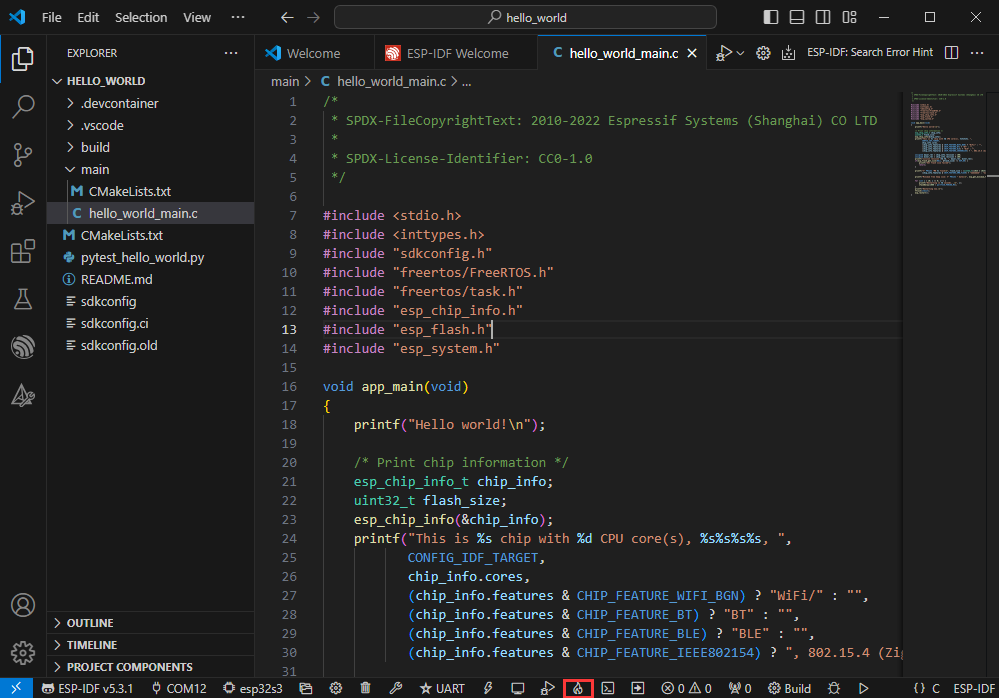
Run the First Arduino Demo
New Project
- Run the Arduino IDE and select
File->New Sketch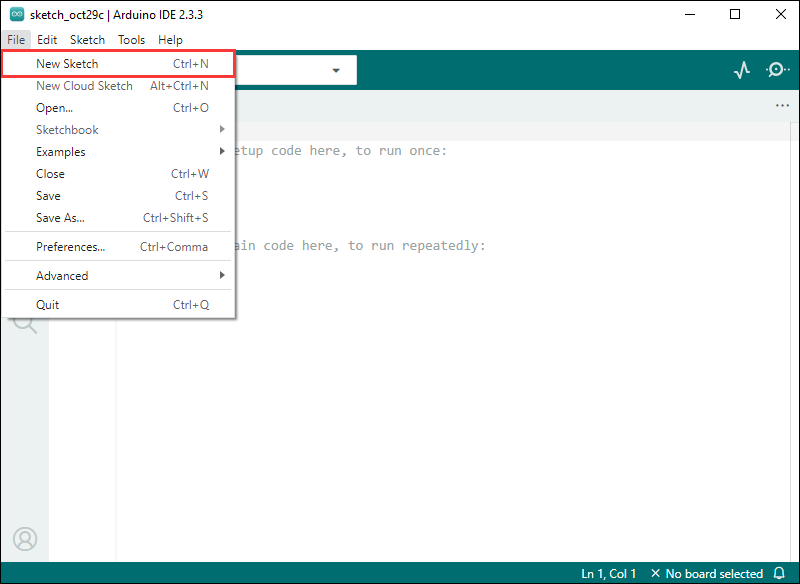
- Enter the code:
void setup() {
  // put your setup code here, to run once:
  Serial.begin(115200);
}

void loop() {
  // put your main code here, to run repeatedly:
  Serial.println("Hello, World!");
  delay(2000);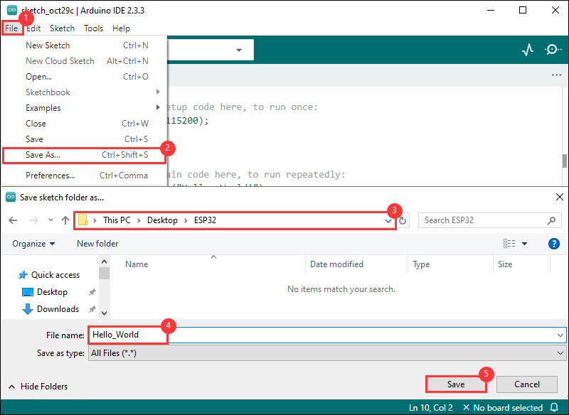
}- Save the project and select
File->Save As.... In the pop-up menu, select the path to save the project, and enter a project name, such as Hello_World, clickSave
Compile and Flash Demos
- Select the corresponding development board, take the ESP32S3 motherboard as an example:
①. Click to select the dropdown menu option Select Other Board and Port;
②. Search for the required development board model esp32s3 dev module and select;
③. Select COM Port;
④. Save the selection.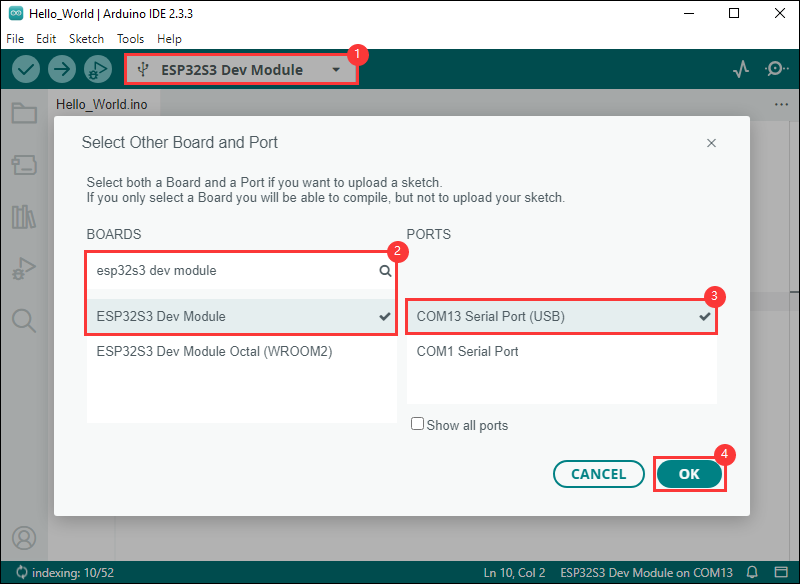
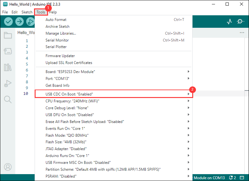
- If the ESP32S3 mainboard only has a USB port, you need to enable USB CDC, as shown in the following diagram:
- Compile and upload the program:
①. Compile the program; ②. Compile and download the program; ③. Download successful.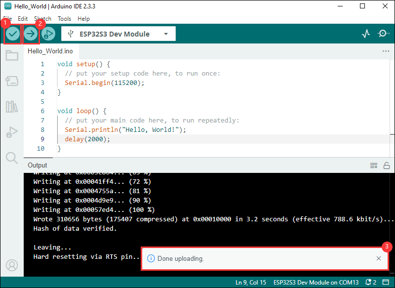
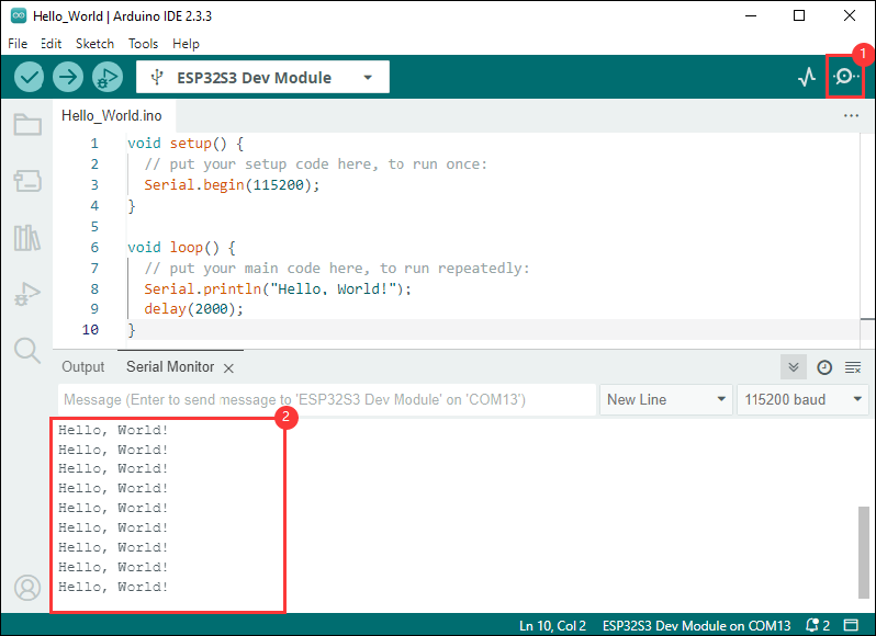
- Open the Serial Monitor window, and the demo will print "Hello World!" every 2 seconds, and the operation is as follows:
Demo

| Demo | Basic Description | Dependency Library |
|---|---|---|
| 01_HelloWorld | Demonstrates the basic graphics library functions and can also be used to test the basic performance of display screens and the display effect of random text | GFX_Library_for_Arduino |
| 02_GFX_AsciiTable | Prints ASCII characters in rows and columns on the display screen according to the screen size | GFX_Library_for_Arduino |
| 03_LVGL_PCF85063_simpleTime | LVGL library displays the current time | LVGL, SensorLib |
| 04_LVGL_QMI8658_ui | LVGL draws acceleration line chart | LVGL, SensorLib |
| 05_LVGL_AXP2101_ADC_Data | LVGL displays PMIC data | LVGL, XPowersLib |
| 06_LVGL_Arduino_v9 | LVGL demonstration | LVGL, Arduino_DriveBus |
| 07_LVGL_SD_Test | LVGL displays the contents of TF card files | LVGL |
| 08_ES8311 | ES8311 driver demo, playing simple audio | —— |
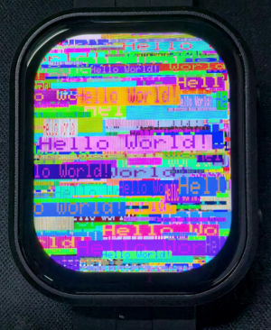
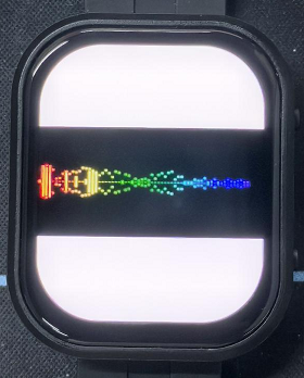
01_HelloWorld
Demo description
- This demo demonstrates how to control the CO5300 display using the Arduino GFX library, demonstrating basic graphics library functionality with dynamically changing text. This code can also be used to test the basic performance of the display and the effect of displaying random text
Hardware connection
- Connect the development board to the computer
Code analysis
- Initialize the display:
if (!gfx->begin()) {
  USBSerial.println("gfx->begin() failed!");
}
- Clear the screen and display text:
gfx->fillScreen(BLACK);
gfx->setCursor(10, 10);
gfx->setTextColor(RED);
gfx->println("Hello World!");
- GIF display:
gfx->setCursor(random(gfx->width()), random(gfx->height()));
gfx->setTextColor(random(0xffff), random(0xffff));
gfx->setTextSize(random(6), random(6), random(2));
gfx->println("Hello World!");
Result demonstration
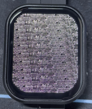
02_GFX_AsciiTable
Demo description
- This demo shows how to display a basic ASCII character table on the SH8601 display by using the Arduino GFX library on an ESP32. The core function of the code is to initialize the display and print ASCII characters by rows and columns on the display according to the screen size
Hardware connection
- Connect the development board to the computer
Code analysis
- Create data bus and graphic display objects
- Here a data bus object for communicating with the display is created, which is initialized with a specific pin configuration. Then a graphical display object gfx is created, passing in parameters such as data bus, reset pin, rotation angle, whether it is an IPS screen, and the width and height of the display
Arduino_DataBus *bus = new Arduino_ESP32QSPI(
  LCD_CS /* CS */, LCD_SCLK /* SCK */, LCD_SDIO0 /* SDIO0 */, LCD_SDIO1 /* SDIO1 */,
  LCD_SDIO2 /* SDIO2 */, LCD_SDIO3 /* SDIO3 */);

Arduino_GFX *gfx = new Arduino_CO5300(bus, -1 /* RST */,
                                      0 /* rotation */, false /* IPS */, LCD_WIDTH, LCD_HEIGHT);
- Draw row and column numbers and character table
- First set the text color to green and print the line numbers one by one on the display. Then set the text color to blue and print the column number. Next, use a loop to draw each character individually to form the character table, with each character using white foreground and black background
gfx->setTextColor(GREEN);
for (int x = 0; x < numRows; x++) {
  gfx->setCursor(10 + x * 8, 2);
  gfx->print(x, 16);
}
gfx->setTextColor(BLUE);
for (int y = 0; y < numCols; y++) {
  gfx->setCursor(2, 12 + y * 10);
  gfx->print(y, 16);
}

char c = 0;
for (int y = 0; y < numRows; y++) {
  for (int x = 0; x < numCols; x++) {
    gfx->drawChar(10 + x * 8, 12 + y * 10, c++, WHITE, BLACK);
  }
}
Result demonstration
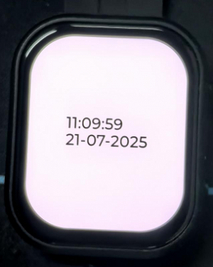
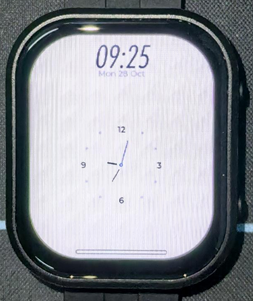
03_GFX_PCF85063_simpleTime
Demo description
- This demo demonstrates how to use the PCF85063 RTC module to display the current time on a CO5300 display, retrieving the time every second and updating the display only when the time changes
Hardware connection
- Connect the development board to the computer
Code analysis
- setup: Initialize the program
- Serial port initialization to provide a channel for outputting error messages
- Initialize the real-time clock chip, including connection check and setting the initial time, to ensure the accuracy of the time
- Initialize the graphic display device, set the background color and brightness, and provide a visual interface for the time display
- loop: Continuously check for time changes and update the time display on the display while the program is running
- Regularly check whether the time has changed, and determine whether the time display needs to be updated by comparing the difference between the current time and the last update time
- Obtain the time information of the real-time clock and format it so that it is displayed correctly on the display
- If the time changes, clear the last time display area, set the text color and size, calculate the center position, and display the new time on the display. Finally save the current time as the last time for comparison next time
Result demonstration
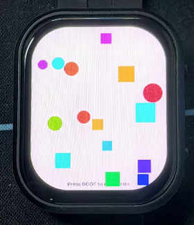
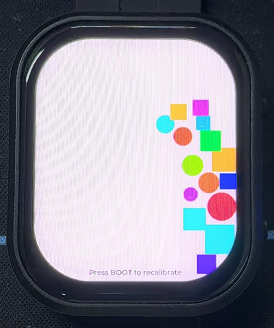
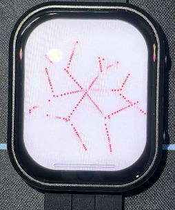
04_LVGL_QMI8658_ui
Demo description
- This demo demonstrates the use of LVGL for graphical display, communicating with the QMI8658 IMU to obtain accelerometer and gyroscope data
Hardware connection
- Connect the development board to the computer
Code analysis
- setup: Responsible for initializing various hardware devices and LVGL graphics library environment
- Serial port initialization:
USBSerial.begin(115200)prepares for serial port debugging - Touch controller initialization: Keep trying to initialize the touch controller
FT3168, if initialization fails, print an error message and wait with a delay, and print a success message if successful - Graphical display initialization: Initialize the graphical display device
gfx, set the brightness, and print the version information of LVGL and Arduino. Next, initialize the LVGL, including registering the print callback function for debugging, initializing the display driver and the input device driver. Create and start the LVGL timer, finally create a label and set the initial text to "Initializing..." - Create a chart: Create a chart object
chart, set the chart type, range, number of data points and other properties of the chart, and add data series for the three axes of acceleration - Acceleration sensor initialization: Initialize acceleration sensor
qmi, configure accelerometer and gyroscope parameters, enable them, and print chip ID and control register information
- Serial port initialization:
- loop
lv_timer_handler(): This is an important function in the LVGL graphics library, which is used to handle various timer events, animation updates, input processing and other tasks of the graphical interface. Calling this function in each loop ensures smooth operation of the graphical interface and timely response to interactions- Read acceleration sensor data: If the acceleration sensor data is ready, read the acceleration data and print it via the serial port, while updating the chart to display the acceleration data. If the gyroscope data is ready, read the gyroscope data and print it via the serial port. Finally add a small delay and increase the frequency of data polling
Result demonstration
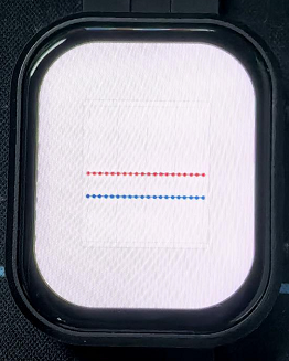
05_LVGL_AXP2101_ADC_Data
Demo description
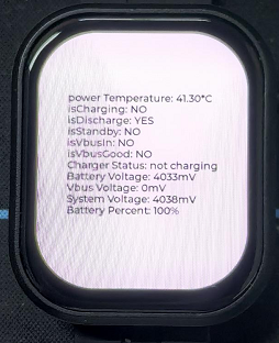
- This demo demonstrates power management using the XPowers library under LVGL, and provides PWR custom button control for screen on and off actions
Hardware connection
- Connect the development board to the computer
Code analysis
- Screen on/off implementation function
void toggleBacklight() {
  USBSerial.println(backlight_on);
  if (backlight_on) {
    for (int i = 255; i >= 0; i--) {
      gfx->Display_Brightness(i);
      delay(3);
    }
  }else{
    for(int i = 0;i <= 255;i++){
      gfx->Display_Brightness(i);
      delay(3);
    }
  }
  backlight_on = !backlight_on;
}
Result demonstration
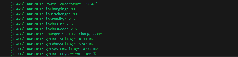
- Display parameters: chip temperature, charging state, discharging state, standby state, Vbus connected, Vbus condition, charger status, battery voltage, Vbus voltage, system voltage, battery percentage
06_LVGL_Arduino_v9
Demo description
- This demo demonstrates the LVGL Widgets example, the frame rate can reach 20~30 frames in the dynamic state. By optimizing the SH8601 display library to achieve a better and smoother frame rate, which can actually be compared to the scenario with dual buffering and dual acceleration enabled in ESP-IDF environment
Hardware connection
- Connect the development board to the computer
Code analysis
- setup: Responsible for initializing various hardware devices and LVGL graphics library environment
- Serial port initialization:
USBSerial.begin(115200)prepares for serial port debugging - I2C bus Initialization:
Wire.begin(IIC_SDA, IIC_SCL);initializes I2C bus for communication with other I2C devices - Expansion chip initialization: Create and initialize the expansion chip
expander, set the pin mode as the output, and make some initial pin state settings - Touch controller initialization: Keep trying to initialize the touch controller
FT3168, if initialization fails, print an error message and wait with a delay, and print a success message if successful - Graphical display initialization: Initialize the graphical display device
gfx, set the brightness, and get the width and height of the screen. Then initialize the LVGL, including registering the print callback function for debugging, setting the touch controller's power mode to monitor mode, initializing the display driver and the input device driver. Create and start the LVGL timer, create a label and set the text, and finally calllv_demo_widgets()to display the LVGL sample widget
- Serial port initialization:
- loop
lv_timer_handler(): This is an important function in the LVGL graphics library, which is used to handle various timer events, animation updates, input processing and other tasks of the graphical interface. Calling this function in each loop ensures smooth operation of the graphical interface and timely response to interactionsdelay(5);: Add a small delay to avoid overoccupying CPU resources
Result demonstration

07_LVGL_SD_Test
Demo description
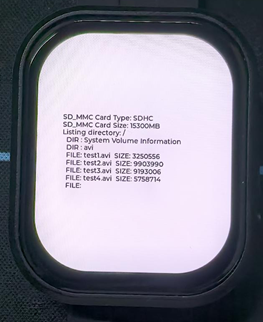
- This demo demonstrates using SDMMC to drive a TF card and output its contents to the display
Hardware connection
- Connect the development board to the computer
- Insert the TF card into the board
Code analysis
- setup: Responsible for initializing various hardware devices and LVGL graphics library environment
- Serial port initialization:
USBSerial.begin(115200)prepares for serial port debugging - I2C bus and expansion chip initialization: Initialize the I2C bus, create and initialize the expansion chip, set its pin mode to output, and print the initial and new states
- Graphics display initialization: Initialize graphics display device, set brightness, initialize LVGL, set display driver and input device driver, create and start LVGL timer
- TF card Initialization and information display: Set the pins of the TF card and attempt to mount the TF card. If the mount fails, an error message is displayed on the serial port and the screen. If the mount is successful, detect the TF card type and display it, get the TF card size and display it. Then call the
listDirfunction to list the contents of the TF card root directory, and display the TF card type, size, and directory list information in the label on the screen
- Serial port initialization:
- listDir: Recursively lists the files and subdirectories in the specified directory
- First print the name of the directory being listed. Then open the specified directory, and if the opening fails, an error message will be returned. If it is not a directory that is opened, an error message is also returned. If it is a directory, then traverse the files and subdirectories in it. For subdirectories, recursively call the
listDirfunction to list their contents. For files, print the file name and file size. Finally, return all collected information as a string
- First print the name of the directory being listed. Then open the specified directory, and if the opening fails, an error message will be returned. If it is not a directory that is opened, an error message is also returned. If it is a directory, then traverse the files and subdirectories in it. For subdirectories, recursively call the
Result demonstration
| SPI interface | ESP32-S3 |
|---|---|
| CS (SS) | GPIO17 |
| DI (MOSI) | GPIO1 |
| DO (MISO) | GPIO3 |
| SCK (SCLK) | GPIO2 |
08_ES8311
Demo description
- This demo demonstrates using I2S to drive the ES8311 chip to play the converted binary audio file
Hardware connection
- Connect the development board to the computer
Code analysis
- es8311_codec_init: Initializes the ES8311 audio codec
- Create a handle
es_handlefor the ES8311 codec - Configure the clock parameters of ES8311, including the main clock and sampling clock frequency, as well as the clock polarity, etc.
- Initialize the codec and set the audio resolution to 16 bits
- Configure sampling frequency
- Configure microphone-related parameters, such as turning off the microphone, setting volume, and microphone gain
- Create a handle
- setup: Perform overall initialization settings, including serial port, pins, I2S, and ES8311 codec
- Initialize serial port for debugging output
- Set a specific pin as output and set it high
- Configure I2S bus, set pins, operating mode, sampling rate, data bit width, channel mode, etc.
- Initialize the I2C bus
- Call the
es8311_codec_initfunction to initialize the ES8311 codec - Play a predefined piece of audio data (
canon_pcm) through the I2S bus
Result demonstration
- Nothing will be shown on the screen if you play the audio file
Working with ESP-IDF
This chapter introduces setting up the ESP-IDF environment setup, including the installation of Visual Studio and the Espressif IDF plugin, program compilation, downloading, and testing of demos, to assist users in mastering the development board and facilitating secondary development.

Environment Setup
Download and Install Visual Studio
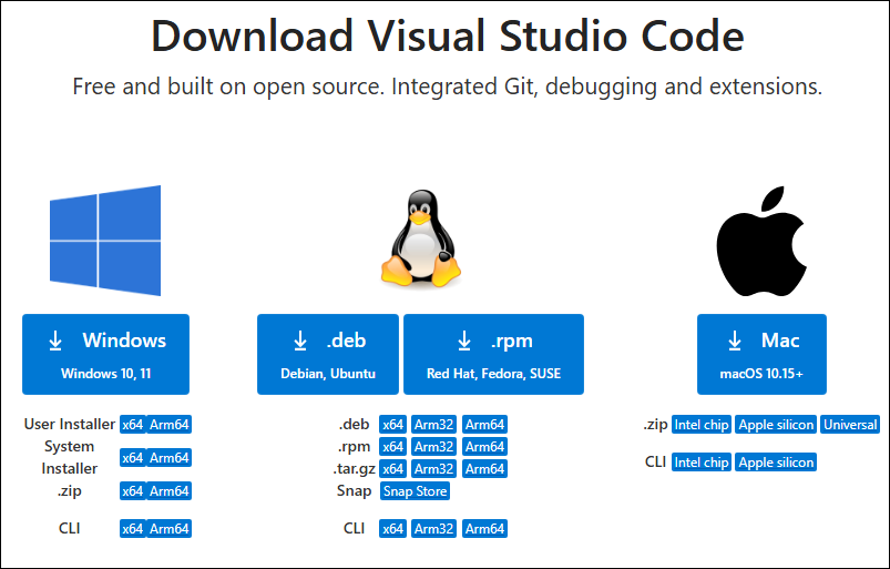
- Open the download page of VScode official website, choose the corresponding system and system bit to download
- After running the installation package, the rest can be installed by default, but here for the subsequent experience, it is recommended to check boxes 1, 2, and 3
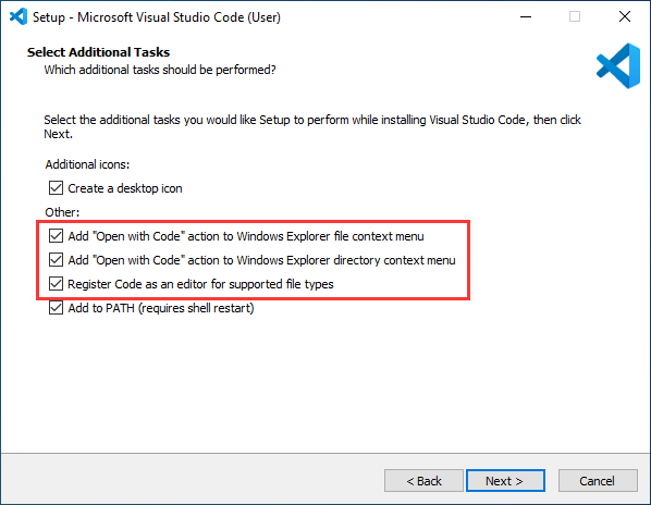
- After the first two items are enabled, you can open VSCode directly by right-clicking files or directories, which can improve the subsequent user experience.
- After the third item is enabled, you can select VSCode directly when you choose how to open it
Install Espressif IDF Plugin
- It is generally recommended to use Install Online. If online installation fails due to network factor, use Install Offline.
- For more information about how to install the Espressif IDF plugin, see Install Espressif IDF Plugin
Run the First ESP-IDF Demo
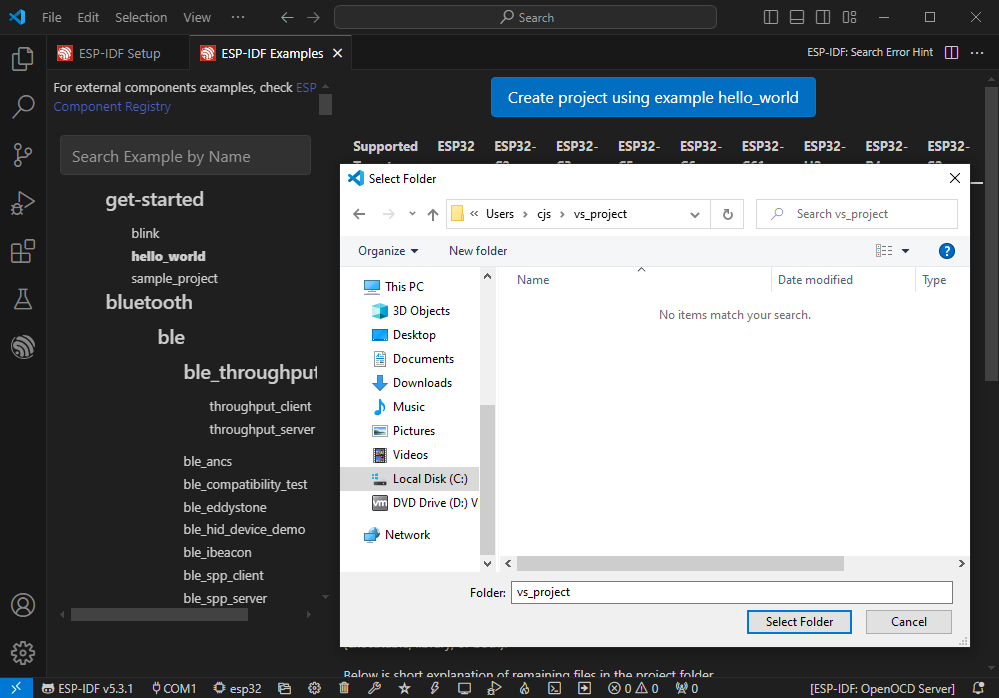
New Project
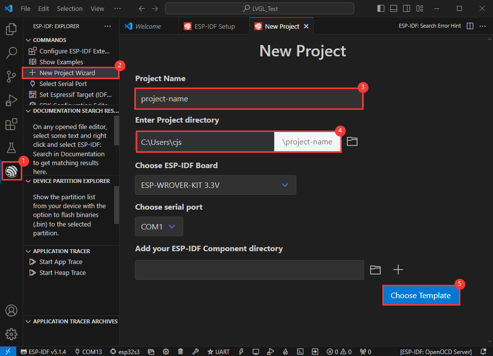
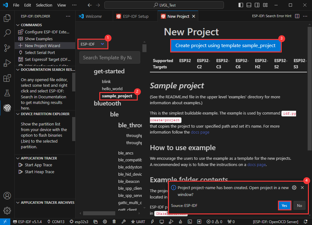
Create Demo
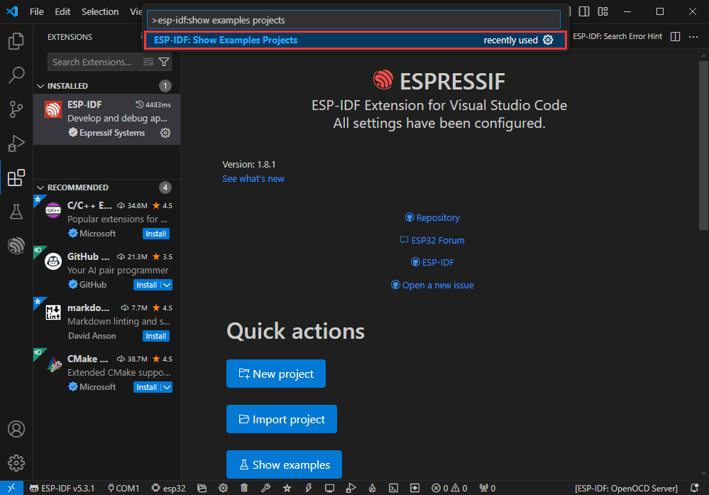
- Using the shortcut F1, enter esp-idf:show examples projects
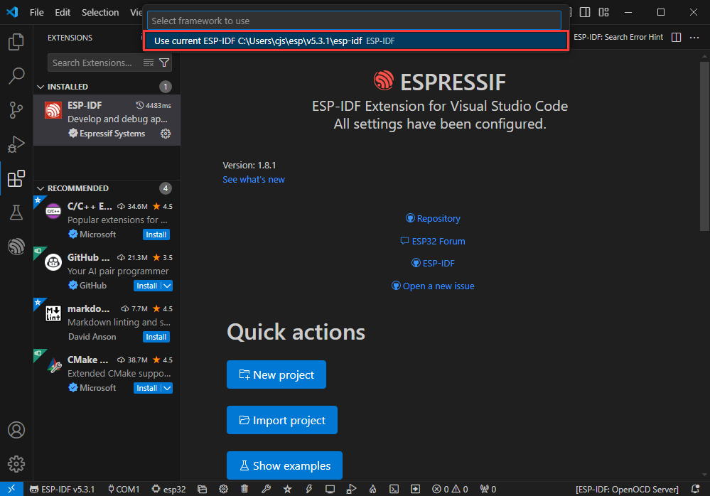
- Select your current IDF version
- Take the Hello world demo as an example
①Select the corresponding demo
②Its readme will state what chip the demo applies to (how to use the demo and the file structure are described below, omitted here)
③Click to create the demo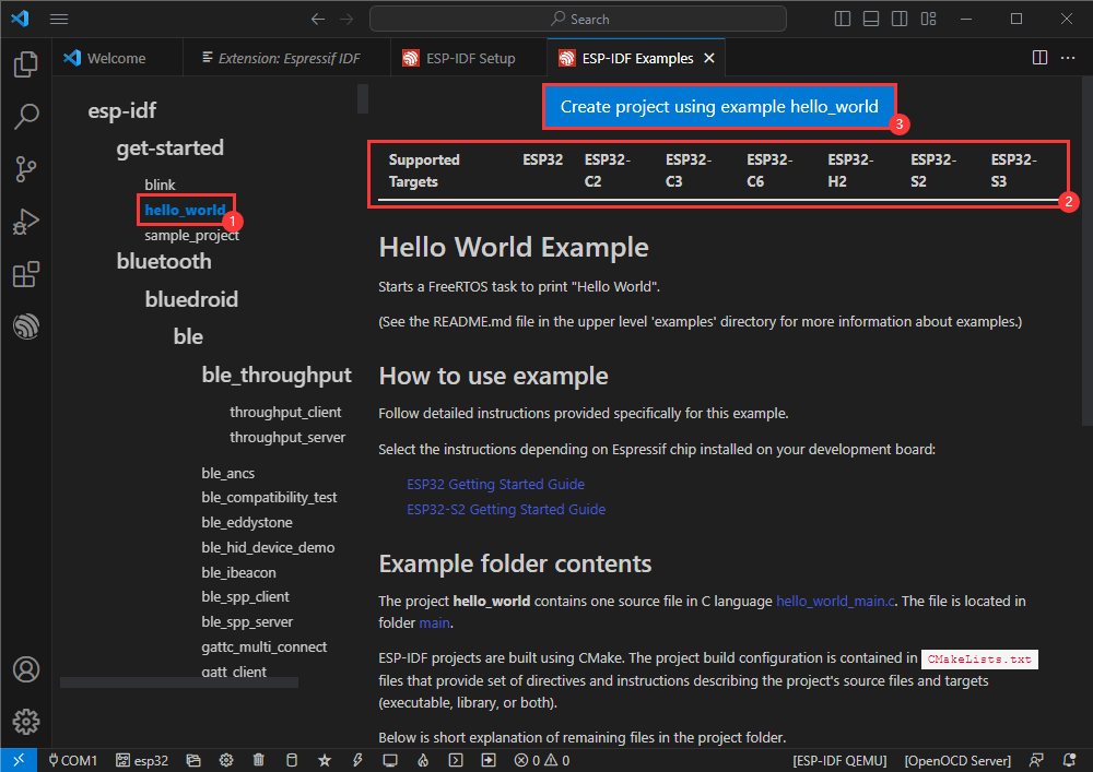
- Select the path to save the demo, and require that the demos cannot use folders with the same name
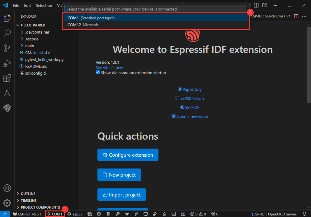
Modify COM Port
- The corresponding COM ports are shown here, click to modify them
- Please select the COM ports according to your device (You can view it from the device manager)
- In case of a download failure, please press the Reset button for more than 1 second or enter download mode, and wait for the PC to recognize the device again before downloading once more
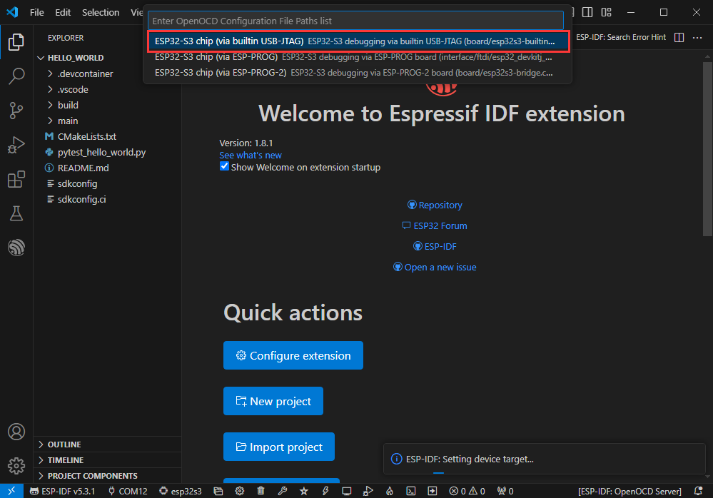
Modify Driver Object
- Select the object we need to drive, which is our main chip ESP32S3
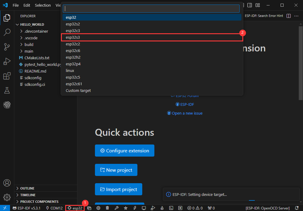
- Choose the openocd path, it doesn't affect us here, so let's just choose one
Other Status Bar Functions
①.ESP-IDF Development Environment Version Manager, when our project requires differentiation of development environment versions, it can be managed by installing different versions of ESP-IDF. When the project uses a specific version, it can be switched to by utilizing it
②.Device flashing COM port, select to flash the compiled program into the chip
③.Select set-target chip model, select the corresponding chip model, for example, ESP32-P4-NANO needs to choose esp32p4 as the target chip
④.menuconfig, click it to Modify sdkconfig configuration file Project configuration details
⑤.fullclean button, when the project compilation error or other operations pollute the compiled content, you can clean up all the compiled content by clicking it
⑥.Build project, when a project satisfies the build, click this button to compile
⑦.Current download mode, the default is UART
⑧.flash button, when a project build is completed, select the COM port of the corresponding development board, and click this button to flash the compiled firmware to the chip
⑨.monitor enable flashing port monitoring, when a project passes through Build --> Flash, click this button to view the log of output from flashing port and debugging port, so as to observe whether the application works normally
⑩.Debug
⑪.Build Flash Monitor one-click button, which is used to continuously execute Build --> Flash --> Monitor, often referred to as "little flame"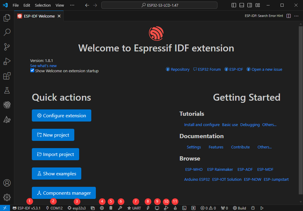
Compile, Flash and Serial Port Monitor
- Click on the all-in-one button we described before to compile, flash and open the serial port monitor
- It may take a long time to compile especially for the first time
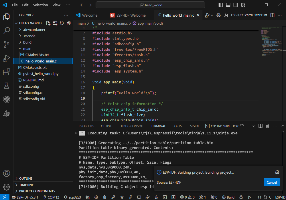
- During this process, the ESP-IDF may take up a lot of CPU resources, so it may cause the system to lag
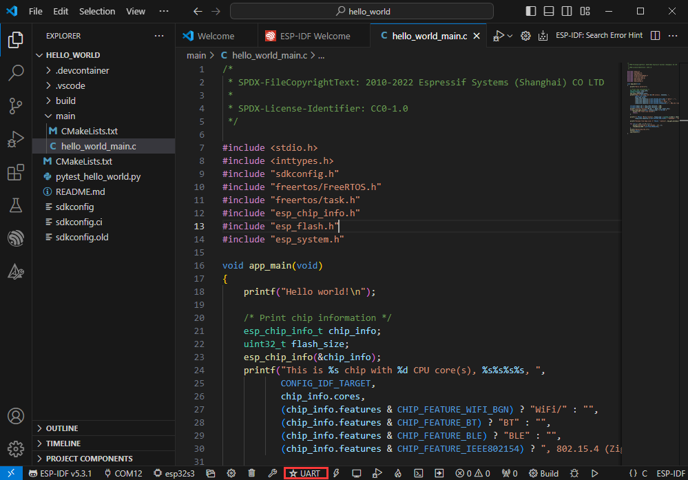
- If it is the first time to flash the program for a new project, you will need to select the download method, and select UART
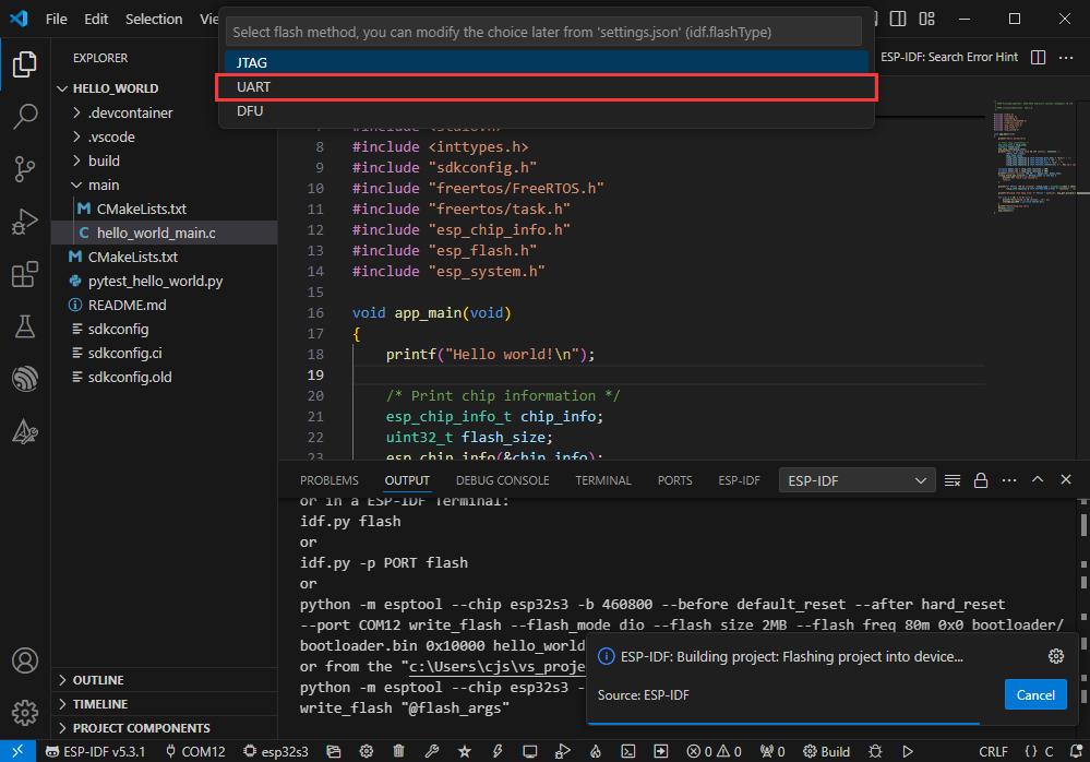
- This can also be changed later in the Download methods section (click on it to pop up the options)
- As it comes with the onboard automatic download circuit, it can be downloaded automatically without manual operation
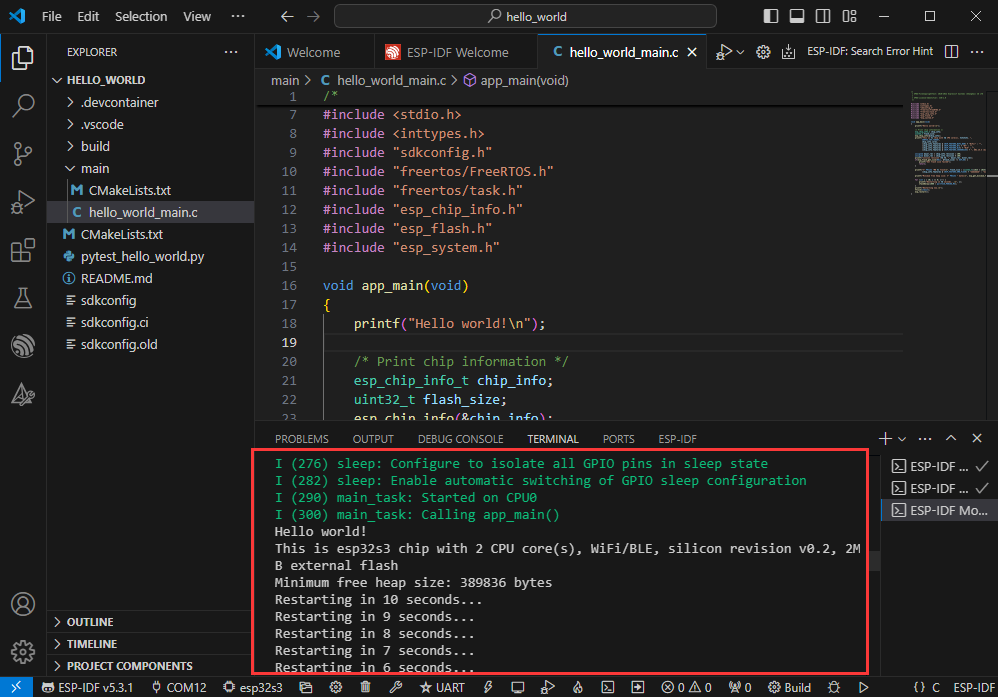
- After successful download, it will automatically enter the serial monitor, you can see the chip output the corresponding information and be prompted to restart after 10S
Use the IDF Demos
Open In the Software
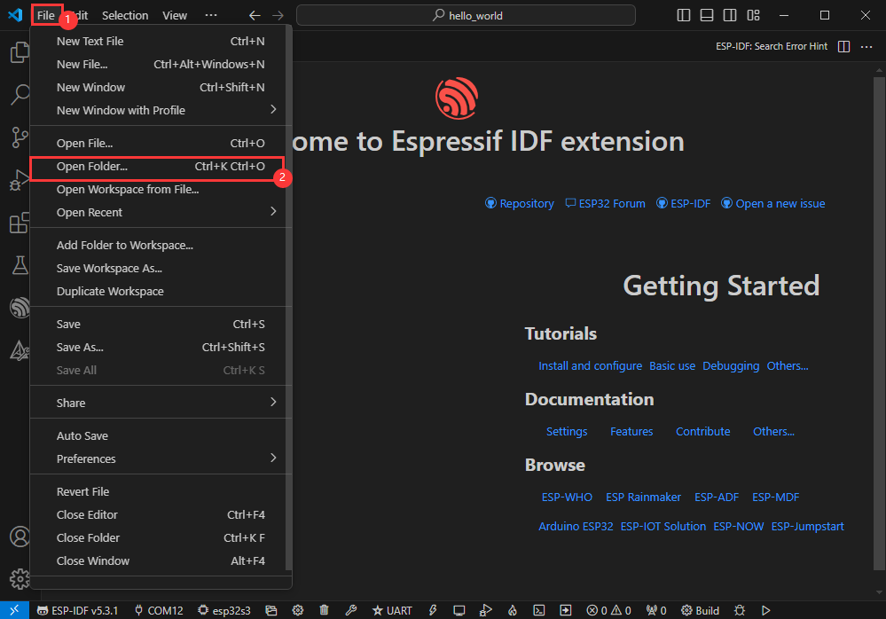
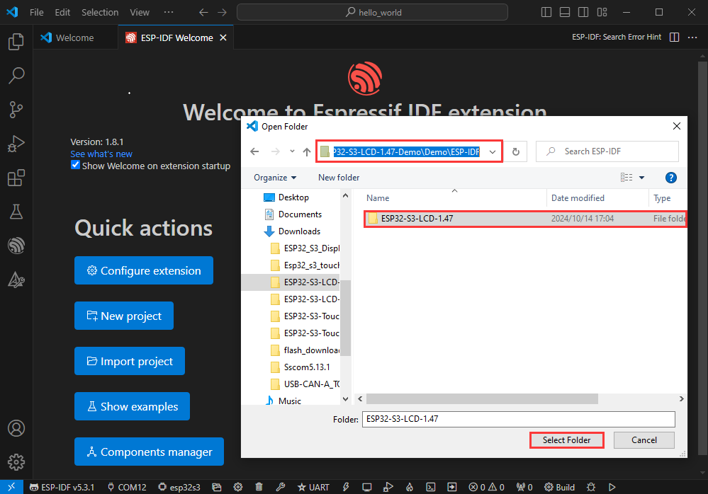
- Open VScode software and select the folder to open the demo
- Select the provided ESP-IDF example and click to select the file (located in the /Demo/ESP-IDF path under demo)
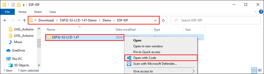
Open from Outside the Software
- Select the project directory correctly and open the project, otherwise it will affect the compilation and flashing of subsequent programs
- After connecting the device, select the COM port and model, click below to compile and flash to achieve program control
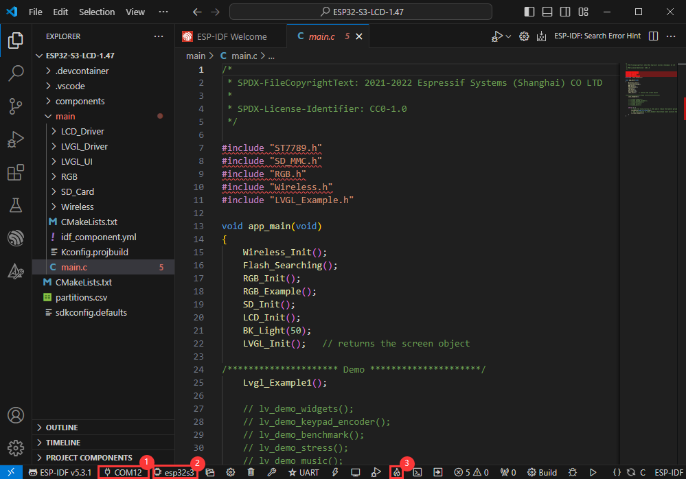
ESP-IDF Project Details
- Component: The components in ESP-IDF are the basic modules for building applications, each component is usually a relatively independent code base or library, which can implement specific functions or services, and can be reused by applications or other components, similar to the definition of libraries in Python development.
- Component reference: The import of libraries in the Python development environment only requires to "import library name or path", while ESP-IDF is based on the C language, and the importing of libraries is configured and defined through
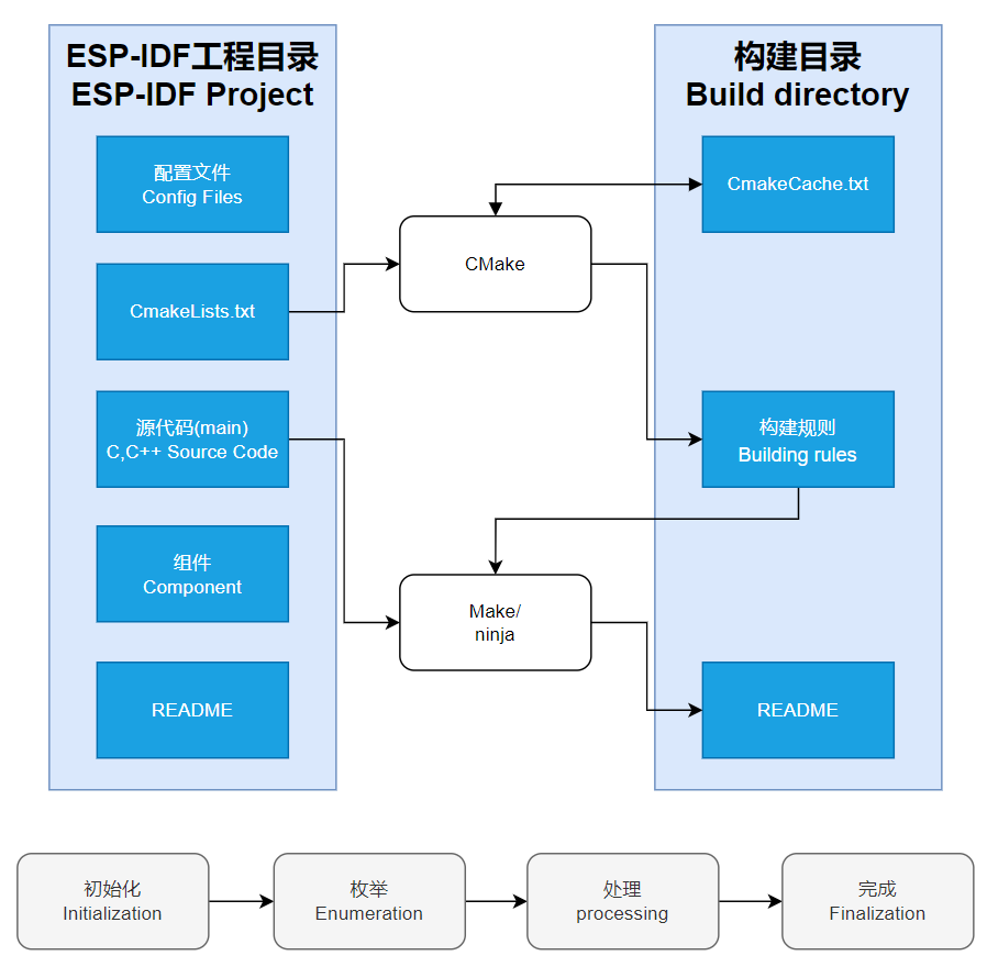
CMakeLists.txt. - The purpose of CmakeLists.txt: When compiling ESP-IDF, the build tool
CMakefirst reads the content of the top-levelCMakeLists.txtin the project directory to read the build rules and identify the content to be compiled. When the required components and demos are imported into theCMakeLists.txt, the compilation toolCMakewill import each content that needs to be compiled according to the index. The compilation process is as follows:
- Component reference: The import of libraries in the Python development environment only requires to "import library name or path", while ESP-IDF is based on the C language, and the importing of libraries is configured and defined through
Demo

| Demo | Basic Description |
|---|---|
| 01_AXP2101 | Obtain power-related data through the ported XPowersLib to drive AXP2101 |
| 02_lvgl_demo_v9 | Run LVGL V9 demo |
| 03_esp-brookesia | Run esp-brookesia demo, based on the V0.4.2 release version |
| 04_Immersive_block | Immersive experience of block shaped objects tilting in the direction of gravity using QMI8658 |
| 05_Spec_Analyzer | Implement a simple audio capture analyzer with LVGL |
| 06_videoplayer | Use LVGL to read AVI video playback from TF card, including audio playback |
01_AXP2101
Demo description
- This demo demonstrates using ESP-IDF to port XPowersLib, and driving AXP2101 to obtain power-related data through the ported XPowersLib
Hardware connection
- Connect the development board to the computer
Code analysis
- i2c_init: Initializes the I2C master in preparation for communication with other devices, such as the PMU
- Configure I2C parameters, including setting the master device mode, specifying the SDA and SCL pins, enabling the pull-up resistor, and determining the clock frequency
- Install the I2C driver and apply the configuration to the actual hardware
- pmu_register_read: Reads a series of bytes of data from a specific register of the PMU
- Perform parameter checks to ensure the incoming parameters are valid and avoid invalid read operations
- Perform I2C operations in two steps, first send the register address to read, then read the data. During the reading process, different processing is carried out according to the length of bytes to be read to ensure accurate reading of the data. At the same time, handle error cases in the I2C communication process and return the corresponding status code so that the upper-layer code can determine if the read operation is successful
Result demonstration
- This demo will not light up the screen
- The serial port monitor displays the parameters: chip temperature, charging state, discharging state, standby state, Vbus connected, Vbus condition, charger status, battery voltage, Vbus voltage, system voltage, battery percentage
02_lvgl_demo_v9
Demo description
- This example runs the LVGL V9 demo
Hardware connection
- Connect the development board to the computer
Result demonstration

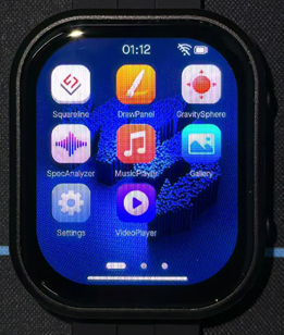
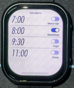
03_esp-brookesia
Demo description
- This demo demonstrates the UI interface running with the esp-brookesia framework
Hardware connection
- Connect the development board to the computer
Result demonstration
04_Immersive_block
Demo description
- This demo demonstrates the QMI8658 driving effect, achieving multiple blocks immersive tilting with gravity
Hardware connection
- Connect the development board to the computer
Result demonstration
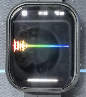
05_Spec_Analyzer
Demo description
- This demo implements the microphone audio capture function, using FFT to analyze the audio and display it on the screen
Hardware connection
- Connect the development board to the computer
Result demonstration
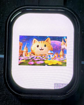
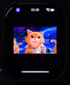
06_videoplayer
Demo description
- This demo demonstrates playing an AVI video file from a TF card, which can also play audio
Hardware connection
- Connect the development board to the computer
Result demonstration
Custom audio
Users can customize audio playback segments by following the steps below (some programming knowledge is required)
- Select the video you want to play (e.g. a.mp4)
- Install ffmpeg tool
- Convert video files to avi format using ffmpeg
ffmpeg -i a.mp4 -vcodec mjpeg -s 'resolution width'x'resolution height' -r 30 -q:v 2 -acodec pcm_s16le -ar 44100 -ac 2 a.avi
- Put the converted avi format file into the /avi/ directory in the TF card
- Insert the TF card into the development board
- Compile and flash
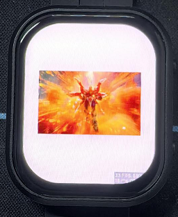
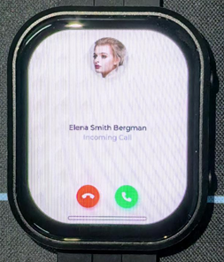
FactoryFirmWare
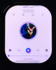
Demo description
- This demo demonstrates an application created using the esp-brookesia master version, implementing features including but not limited to touch, display, audio capture, audio playback, clock, gyroscope, audio-visual playback, and PMU control
Hardware connection
- Connect the development board to the computer
- Flash firmware using a firmware burning tool (online, locally, etc.)
Result demonstration
Custom audio
Users can customize audio playback segments by following the steps below (some programming knowledge is required)
- Select the video you want to play (e.g. a.mp4)
- Install ffmpeg tool
- Convert video files to avi format using ffmpeg
ffmpeg -i a.mp4 -vcodec mjpeg -s 'resolution width'x'resolution height' -r 30 -q:v 2 -acodec pcm_s16le -ar 44100 -ac 2 a.avi
- Put the converted avi format file into the /avi/ directory in the TF card
- Insert the TF card into the development board
- Compile and flash
Flash Firmware Flashing and Erasing
- The current demo provides test firmware, which can be used to test whether the onboard device functions properly by directly flashing the test firmware
- bin file path:
..\ESP32-S3-Touch-AMOLED-2.06-Demo\Firmware
Resources
Schematic Diagram
Project Diagram
Demo
Datasheets
ESP32-S3
Other Components
- QMI8658 Datasheet
- PCF85063 Datasheet
- AXP2101 Datasheet
- ES8311 Datasheet
- ES8311 User Guide
- FT3168 Datasheet
- ES7210 Datasheet
Softwares
- Zimo221 Chinese character conversion software
- Image2Lcd image bitmap conversion software
- flash_download_tool_3.9.7
Other Resource Links
- Image bitmap conversion tutorial
- Font library conversion tutorial
- MicroPython official documentation
- ESP32 Arduino Core documentation
- arduino-esp32
- ESP-IDF
FAQ
Question: How to get more library support for the demo?
You can subscribe to this repository and raise an issue to describe your requirements. The engineers will assess your request as soon as possible: ESP32-display-support
Question: What platforms does the AI large model example of speech dialog support?
The product is equipped with ES8311 audio codec chip, onboard speaker, and SMD microphone. And it can achieve voice dialogue function;
Integration with various platforms has been fully verified and completed at present, supporting mainstream platforms such as DouBao, Wenxin Yiyan, ChatGPT, and Tuya Smart. The demos will gradually be opened up to ESP32-AIChats
Question: How is the heat generation of this product, and will it affect the display?
The measured temperature is at room temperature 20°C, the wifi STA and AP modes are turned on, and the battery is in the charging state. The test lasts for half an hour, and the highest temperature read through AXP2101 temperature data is 46 ℃. During the normal discharge process, the temperature will decrease by 3-4 ℃. If WiFi/Bluetooth function is not turned on, it can maintain a stable temperature of around 36 ℃
This AMOLED screen can withstand high temperatures; at 40 to 60 degrees Celsius, it will not affect the screen display or touch function. In high temperature and high humidity conditions, there may be some polarization, which is within the normal range.
For this product, it is recommended to use the low-power operation mode of ESP32-S3 to complete the application in some scenarios.
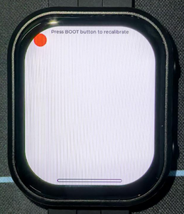
Question: Why does the flashing fail?
1. When the serial port is occupied, the flashing will fail. Close the serial port monitor and try to flash again
2. When the ESP32 program crashes, the flashing will fail, and the development module needs to be completely powered off, hold down BOOT and power it on again to enter the strong download mode and then flash it. It will not automatically exit the download mode after flashing, so you need to power off and restart again
Note: To power on this product again, press and hold the PWR button for at least 6 seconds, and then press the PWR button again
Question: Why did the compilation fail?
When the project fails to be compiled, check the development environment.
- Arduino IDE compiling the project shows the situation in the image, you need to modify Partition Scheme->16M Flash(3MB APP/9.9MB FATFS)。
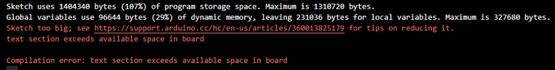
- When the ESP-IDF project compilation fails, delete the build, managed_components, and dependencies.lock, and then compile again. If the error persists, check whether the ESP-IDF version and the CMakeList.txt in the project directory are correctly recognized
Question: Why does the module keep resetting?
In this case, due to the crash of the program, the USB cannot work normally, you can press and hold the BOOT button and then power on, at this time, the module can enter the download mode to flash the firmware (program) to solve the situation.
Question: How to deal with the first compilation of the program being extremely slow?
In the Arduino IDE, the first compilation loads and compiles all the dependencies, so it's normal for the first compilation task to be time-consuming. Just wait patiently
Question: How to handle the display "waiting for download..." on the serial port after successfully ESP-IDF flashing?
Power it on again
Question: How to measure the battery voltage of this product?
This product has an on-board AXP2101, which can measure all kinds of battery data, such as: chip temperature, whether it is charged, whether it is connected to the power supply, charging status, battery voltage, charging voltage, battery power, etc.
Question: This product measures the percentage of battery remaining capacity. Why does the result fluctuate greatly?
The battery capacity measurement of the AXP2101 is based on battery voltage, but battery capacity does not vary linearly, so large percentage fluctuations may occur during measurement. Especially in the case of plugging and unplugging chargers, load changes, or battery aging, the fluctuations become more noticeable. The measured percentages are for reference only, and the actual voltage is used as a measure of capacity.
Question: Can you provide the 3D file for the casing?
It is not provided.
Question: Can both buttons of this product be programmed for use?
Yes, the two buttons of this product are BOOT and PWR. The functions are as follows:
1. BOOT: Press and then power on, and the development board enters download mode (commonly used when the program freezes or the USB GPIO is occupied); under normal working conditions, the GPIO0 can detect the high and low level of the button to determine the action, and the low level is pressed, which can recognize click, double-click, multi-click, and long-press actions.
2.PWR: In the power-on state, press and hold for 6s to power off, in the power-off state (power off to charge the battery), click to power on; Under normal working conditions, the action can be judged by the high and low levels of the EXIO6 detection buttons of the extended IO, and the high level is pressed, which can identify the actions of single click, double click, multiple click and long press (long press should not exceed 6s, otherwise the power will be turned off).
Question: Does this product support Bluetooth?
The core chip of this product is ESP32-S3R8, which supports wireless communication functions such as 2.4GHz WiFi and Bluetooth LE 5, and has an onboard SMD antenna, and the antenna gain has been adjusted to the optimum, which can support the use of Bluetooth and WiFi. For details, please refer to ESP32-S3 datasheet
Question: Does this product support Chinese display?
This product uses ESP32-S3R8 as the core, connects the screen via QSPI protocol, fully supports Chinese display, but requires meeting the following conditions:
1. Character encoding support is required, and strings that support UNICODE-8 encoding can be rendered to the screen
2. Font library support
3. Display library support, LVGL or Arduino_GFX are supported
Question: What is the maximum brightness of the screen of this product? How to control the screen brightness?
600nit;
Write 0x00 (darkest, backlight off) ~ 0xFF (brightest) to the 0x51 via QSPI to control the brightness.
Question: What chip is used for the screen of this product?
Screen display chip: CO5300;
Screen touch chip: FT3168
Question: What is this product developed with?
ESP32-S3-Touch-AMOLED-2.06 is based on the ESP32-S3R8 chip, supports ESP-IDF and its ecosystem, and can be developed using ESP-IDF or arduino-esp32 Core. ESP-IDF can be used with Vscode, and arduino-esp32 can be used with Arduino IDE or PlatformIO.
Question: Is this product waterproof?
It is not waterproof and should be kept dry when used
Question: What size is this battery?
The recommended battery specification is 4*27*28 400mAh, which can be used for about 1 hour in the regular full-light state, 3~4 hours when the screen backlight is turned off, and about 6 hours in full low-power scenarios.
Question: Why do the LVGL examples run less smoothly on the Arduino IDE compared to ESP-IDF?
The upper driver of the GFX Arduino LVGL is the Arduino TFT library, and the ability to read and write images accelerated by DMA is limited in this scenario. The LVGL examples provided by ESP-IDF enable double buffering and anti-tearing optimization operations, so the results are better.
Question: How to check the COM port I use?
Windows system:
①View through Device Manager: Press the Windows + R keys to open the "Run" dialog box; Input devmgmt.msc and press Enter to open Device Manager; Expand the "Port (COM and LPT)" section, here it will list all the COM ports and their current status.
②Use the command prompt to view: Open the Command Prompt (CMD); enter the mode command, which will display status information for all COM ports.
③Check hardware connections: If you have already connected external devices to the COM port, the device usually occupies a port number, which can be determined by checking the connected hardware.
Linux system:
①Use the dmesg command to view: Open the terminal.
①Use the ls command to view: Enter ls /dev/ttyS* or ls /dev/ttyUSB* to list all serial port devices.
③Use the setserial command to view: Enter setserial -g /dev/ttyS* to view the configuration information of all serial port devices.
Question: Why is there no output from the monitor after running the code, even though the code is correct and successfully flashed?
The Type-C flashing and debugging port of ESP32-S3-Touch-AMOLED-2.06 is directly output from ESP32-S3 USB. In the Arduino IDE development environment, it supports printf function for printing and output. If you want to support Serial function for printing and output, you need to enable USB CDC On Boot function or HWCDC declaration. For this, please refer to the demonstration in the demo. ESP-IDF usually uses ESP_LOGD and ESP-ERROR_CECK for printing output.
Support
Monday-Friday (9:30-6:30) Saturday (9:30-5:30)
Email: services01@spotpear.com
[Tutorial Navigation]
- Introduction
- Usage Instructions
- Working with Arduino
- Working with ESP-IDF
- Environment Setup
- Run the First ESP-IDF Demo
- New Project
- Create Demo
- Modify COM Port
- Modify Driver Object
- Other Status Bar Functions
- Compile, Flash and Serial Port Monitor
- Use the IDF Demos
- Demo
- Flash Firmware Flashing and Erasing
- Resources
- FAQ
- Question: How to get more library support for the demo?
- Question: What platforms does the AI large model example of speech dialog support?
- Question: How is the heat generation of this product, and will it affect the display?
- Question: Why does the flashing fail?
- Question: Why did the compilation fail?
- Question: Why does the module keep resetting?
- Question: How to deal with the first compilation of the program being extremely slow?
- Question: How to handle the display "waiting for download..." on the serial port after successfully ESP-IDF flashing?
- Question: How to measure the battery voltage of this product?
- Question: This product measures the percentage of battery remaining capacity. Why does the result fluctuate greatly?
- Question: Can you provide the 3D file for the casing?
- Question: Can both buttons of this product be programmed for use?
- Question: Does this product support Bluetooth?
- Question: Does this product support Chinese display?
- Question: What is the maximum brightness of the screen of this product? How to control the screen brightness?
- Question: What chip is used for the screen of this product?
- Question: What is this product developed with?
- Question: Is this product waterproof?
- Question: What size is this battery?
- Question: Why do the LVGL examples run less smoothly on the Arduino IDE compared to ESP-IDF?
- Question: How to check the COM port I use?
- Question: Why is there no output from the monitor after running the code, even though the code is correct and successfully flashed?
- Support